1989 MITSUBISHI GALANT sensor
[x] Cancel search: sensorPage 494 of 1273
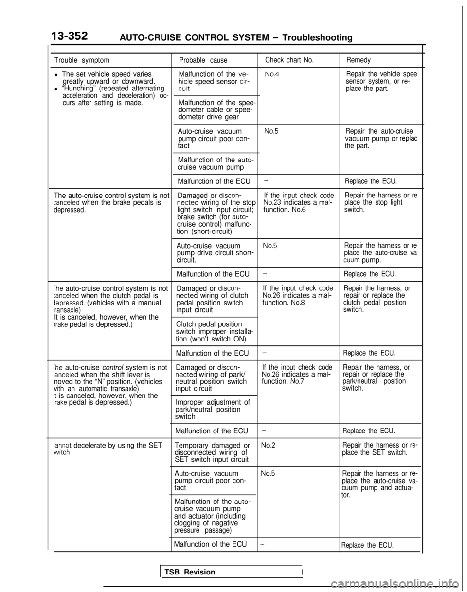
13-352AUTO-CRUISE CONTROL SYSTEM - Troubleshooting
Trouble symptomProbable causeCheck chart No.
Remedy
l The set vehicle speed varies Malfunction of the ve-No.4Repair the vehicle speegreatly upward or downward.hicle speed sensor cir-l “Hunching” (repeated alternatingsensor system, or re-witplace the part.
acceleration and deceleration) oc- curs after setting is made.
Malfunction of the spee-
dometer cable or spee-
dometer drive gear
Auto-cruise vacuum
No.5Repair the auto-cruisepump circuit poor con-vacuum pump or replactactthe part.
Malfunction of the auto-cruise vacuum pump Malfunction of the ECU
-Replace the ECU.
The auto-cruise control system is not Damaged or discon-If the input check code Repair the harness or rezanceled when the brake pedals is netted wiring of the stopNo.23 indicates a mal-
depressed.light switch input circuit; function. No.6place the stop light
switch.
brake switch (for auto-cruise control) malfunc-
tion (short-circuit)
Auto-cruise vacuum
No.5Repair the harness or repump drive circuit short- place the auto-cruise va
circuit.cuum pump.
Malfunction of the ECU
-Replace the ECU.
The auto-cruise control system is not Damaged or discon-If the input check code
Repair the harness, or:anceled when the clutch pedal is netted wiring of clutchNo.26 indicates a mal-repair or replace thedepressed. (vehicles with a manual
pedal position switchfunction. No.8clutch pedal position
ransaxle)input circuitswitch.
It is canceled, however, when theIrake pedal is depressed.) Clutch pedal position
switch improper installa-
tion (won’t switch ON)
Malfunction of the ECU
-Replace the ECU.
*he auto-cruise control system is not Damaged or discon-If the input check code
Repair the harness, or:anceled when the shift lever is netted
wiring of park/No.26 indicates a mal-repair or replace the
noved to the “N” position. (vehicles neutral position switchfunction. No.7park/neutral position
vith an automatic transaxle)input circuit switch.t is canceled, however, when thebrake pedal is depressed.)
Improper adjustment of
park/neutral position
switch
Malfunction of the ECU-Replace the ECU.
anc$ decelerate by using the SET Temporary damaged orNo.2Repair the harness or re-disconnected wiring of
SET switch input circuitplace the SET switch.
Auto-cruise vacuumNo.5Repair the harness or re-pump circuit poor con-
tactplace the auto-cruise va-
cuum pump and actua-
tor.Malfunction of the auto-cruise vacuum pump
and actuator (including
clogging of negative
pressure passage)
Malfunction of the ECU-Replace the ECU.
TSB RevisionI
Page 495 of 1273
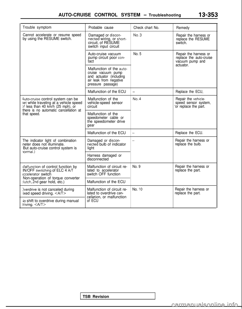
AUTO-CRUISE CONTROL SYSTEM - Troubleshooting13-353
Trouble symptom
Probable causeCheck chart No.Remedy
Cannot accelerate or resume speed
No.3
by using the RESUME switch. Damaged or discon- netted wiring, or short-
Repair the harness orcircuit, of RESUMEreplace the RESUMEswitch.
switch input circuit
Auto-cruise vacuum
No. 5Repair the harness orpump circuit poor con-replace the auto-cruisetactvacuum pump and
actuator.
Malfunction of the auto-cruise vacuum pump
and actuator (including
air leak from negative
pressure passage)
Malfunction of the ECU-Replace the ECU,
4uto-cruise control system can be Malfunction of theNo.4Repair the vehicle-set while traveling at a vehicle speed vehicle-speed sensorspeed sensor system,3f less than 40 km/h (25 mph), orcircuit‘or replace the part.
there is no automatic cancellation at
that speed.
Malfunction of thespeedometer cable orthe speedometer drivegear
The indicator light of combination
neter does not illuminate. But auto-cruise control system is
iormal.)
Malfunction of the ECU-Replace the ECU.
Damaged or discon--Repair the harness ornetted bulb of indicatorreplace the bulb.light
Harness damaged ordisconnected
vlalfunction of control function by Malfunction of circuit re-No. 9Repair the harness orIN/OFF switchrng of ELC 4 ATlated to accelerator
replace the part.accelerator switchswitch OFF function
Non-operation of torque converter
:lutch, 2nd gear hold, etc.) Malfunction of the ECU
Overdrive is not canceled during Malfunction of circuit re-No. 10Repair the harness or
ixed speed driving. lated to overdrive can-replace the part.cellation, or malfunction\lo shift to overdrive during manualIriving.
of ECU
TSB Revision
Page 497 of 1273
AUTO-CRUISE CONTROL SYSTEM - Troubleshooting13-355
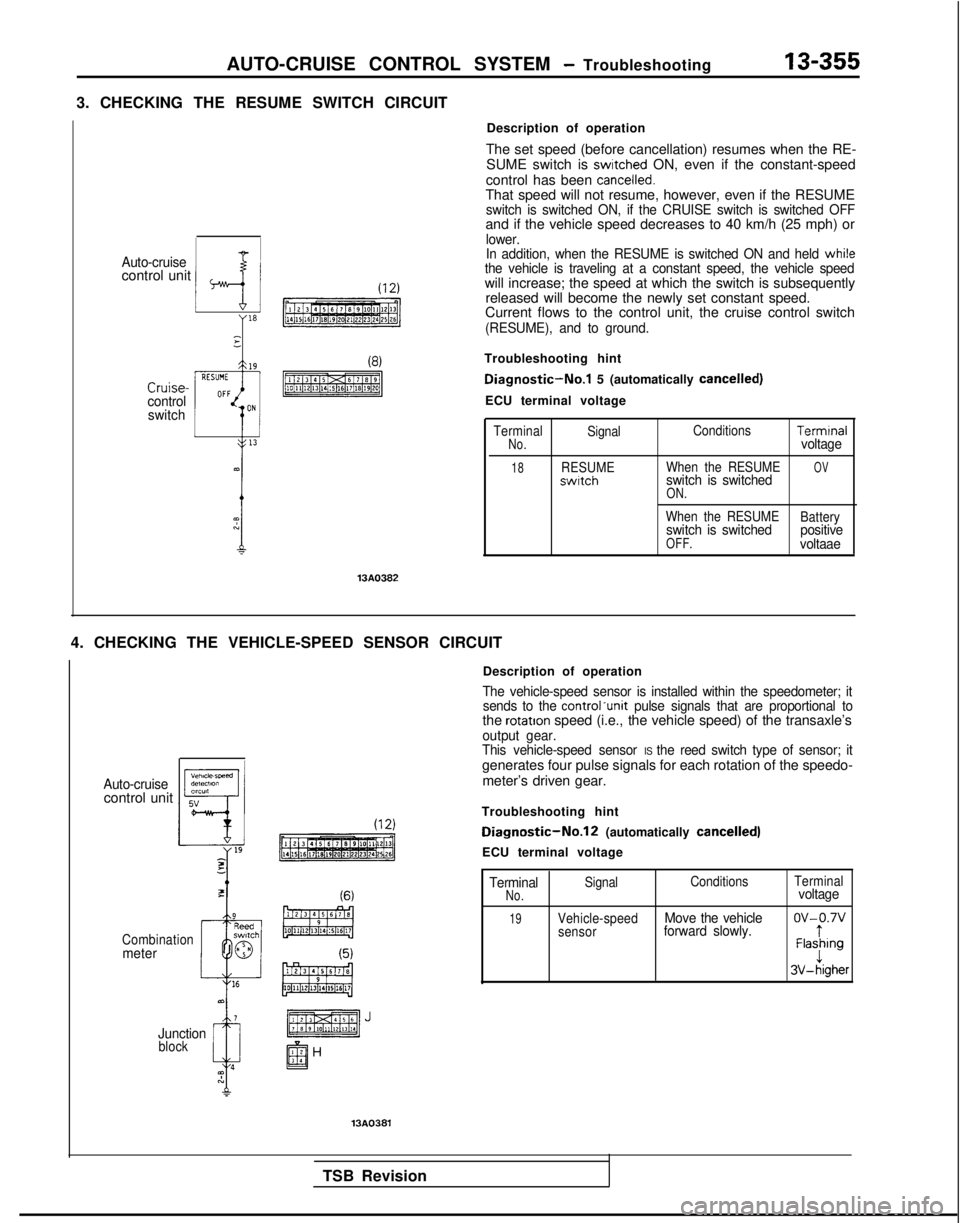
3. CHECKING THE RESUME SWITCH CIRCUIT
Auto-cruisecontrol unit
--f
Y
Cruise-control
switch
Description of operation
The set speed (before cancellation) resumes when the RE- SUME switch is
swrtched ON, even if the constant-speed
control has been cancelled.That speed will not resume, however, even if the RESUMEswitch is switched ON, if the CRUISE switch is switched OFFand if the vehicle speed decreases to 40 km/h (25 mph) orlower.
In addition, when the RESUME is switched ON and held whi!ethe vehicle is traveling at a constant speed, the vehicle speedwill increase; the speed at which the switch is subsequently released will become the newly set constant speed.
Current flows to the control unit, the cruise control switch
(RESUME), and to ground.
Troubleshooting hint
Diagnostic-No.1 5 (automatically cancelled)
ECU terminal voltage 13AO382
Terminal
Signal ConditionsTermrnalNo.voltage
18RESUME
When the RESUMEOVswrtchswitch is switchedON.
When the RESUME
Batteryswitch is switchedpositiveOFF.voltaae
4. CHECKING THE VEHICLE-SPEED SENSOR CIRCUIT
Auto-cruisecontrol unit
Combinationmeter
Junction
block
(6)
Description of operation
The vehicle-speed sensor is installed within the speedometer; itsends to the controlunit pulse signals that are proportional tothe rotatron speed (i.e., the vehicle speed) of the transaxle’soutput gear.
This vehicle-speed sensor IS the reed switch type of sensor; itgenerates four pulse signals for each rotation of the speedo-
meter’s driven gear.
Troubleshooting hint
Diagnostic-No.12 (automatically cancelled)
ECU terminal voltage
TerminalSignal Conditions
TerminalNo.voltage
19Vehicle-speedMove the vehicleov-0.7vsensorforward slowly.tFlashingJ3V-higher
13A0381
TSB Revision
Page 500 of 1273
13-358AUTO-CRUISE CONTROL SYSTEM - Troubleshooting
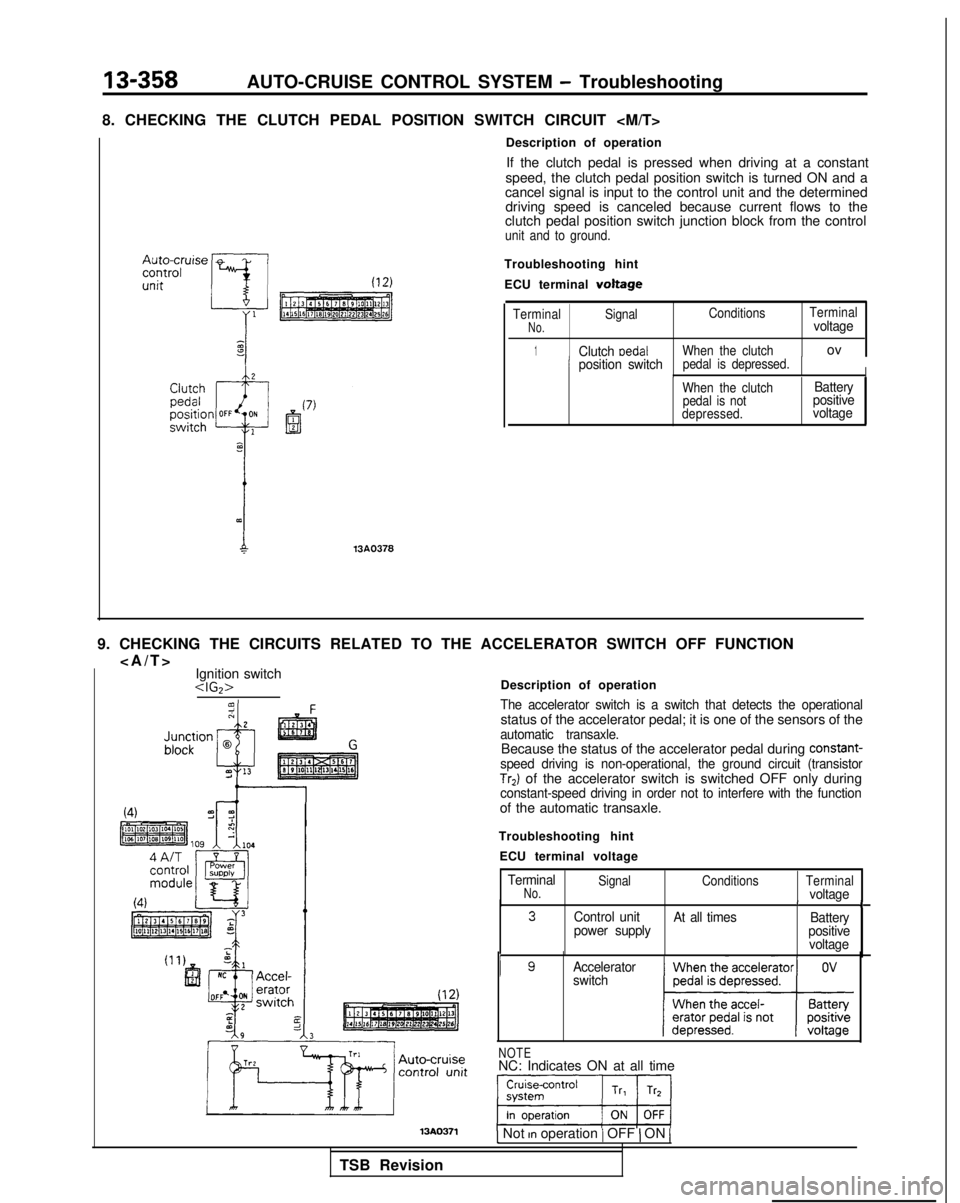
8. CHECKING THE CLUTCH PEDAL POSITION SWITCH CIRCUIT
13A0378
Description of operation If the clutch pedal is pressed when driving at a constant
speed, the clutch pedal position switch is turned ON and a
cancel signal is input to the control unit and the determined driving speed is canceled because current flows to the
clutch pedal position switch junction block from the control
unit and to ground.
Troubleshooting hint
ECU terminal
voltage
Terminal Signal Conditions
TerminalNo.voltage
1Clutch medalWhen the clutchov
Iposition switchpedal is depressed.IWhen the clutch
pedal is not
depressed.Battery
positive
voltage
9. CHECKING THE CIRCUITS RELATED TO THE ACCELERATOR SWITCH OFF FUNCTION
>
Ignition switch
Troubleshooting hint ECU terminal voltage
TerminalNo.Signal ConditionsTerminalvoltageII3Control unit
At all times Battery
power supply positive
voltage
I gAccelerator
switch
NOTENC: Indicates ON at all time
1 Not rn operation / OFF ) ON 1
TSB Revision
Page 502 of 1273
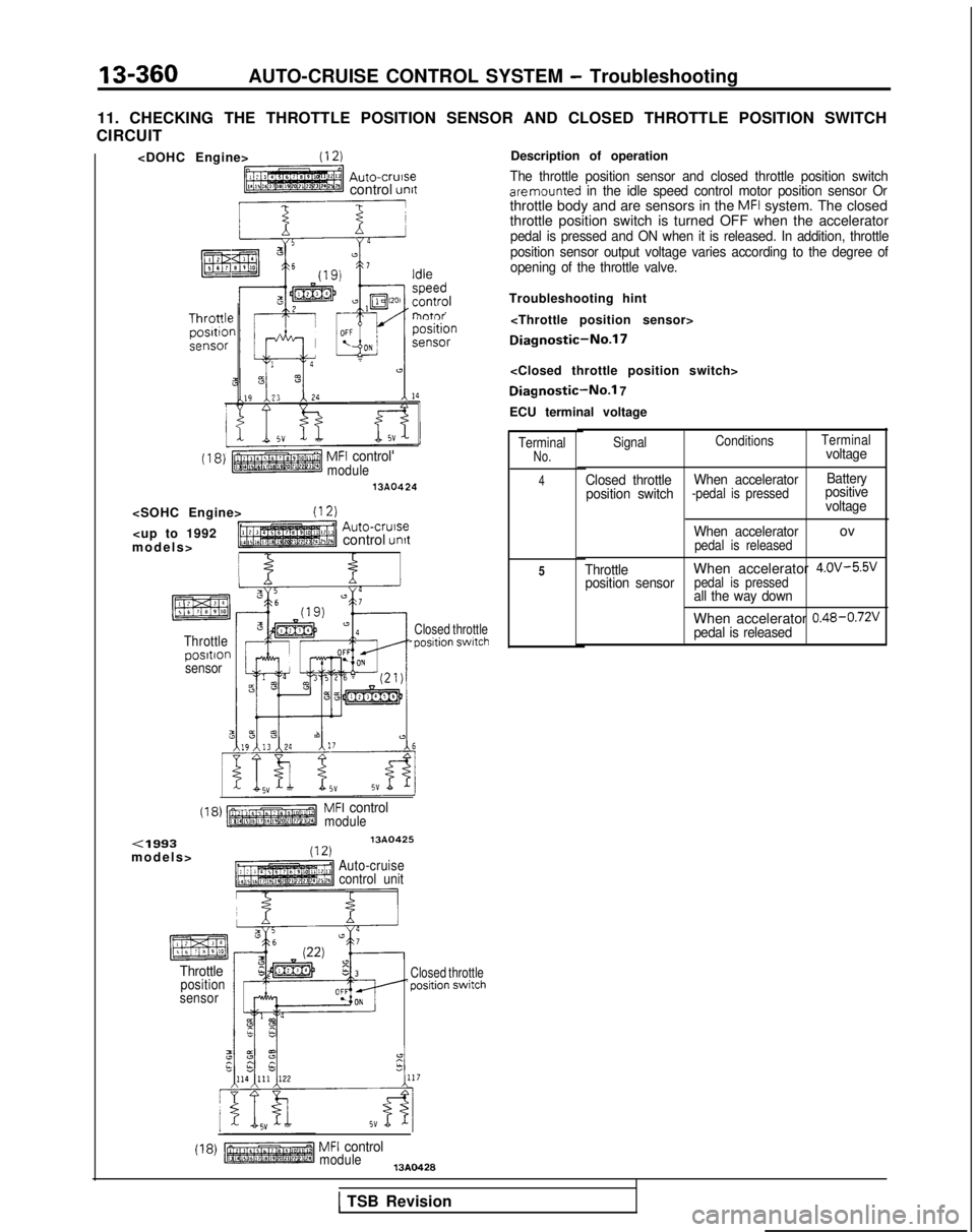
13-360AUTO-CRUISE CONTROL SYSTEM - Troubleshooting
11. CHECKING THE THROTTLE POSITION SENSOR AND CLOSED THROTTLE POSITION S\
WITCH
CIRCUIT
Auto-crursecontrol unit
I 2EB16 I
lntr’
(18)
MFI controlmodule1380424
>
control
unrt
I f
Throttleposrtronsensor
Closed throttle-position swrtch
(18)MFI controlmodule
<1993models
>
13A0425(12)Auto-cruise
control unit
Throttleposition
sensorClosed throttle ‘position
switch
(18)MFI controlmodule13A0428
Description of operation
The throttle position sensor and closed throttle position switchare mounted in the idle speed control motor position sensor Orthrottle body and are sensors in the MFI system. The closed
throttle position switch is turned OFF when the accelerator
pedal is pressed and ON when it is released. In addition, throttle
position sensor output voltage varies according to the degree of
opening of the throttle valve.
Troubleshooting hint
Diagnostic-No.17
Diagnostic-No.1 7
ECU terminal voltage
TerminalNo.
4
5 Signal
Conditions
Terminal
voltage
Closed throttle When accelerator Battery
position switch
-pedal is pressedpositive voltage
When accelerator
pedal is releasedov
ThrottleWhen accelerator 4.0v-5%’position sensorpedal is pressedall the way down
When accelerator 0.48~0.72v
pedal is released
1 TSB Revision
Page 504 of 1273
13-362AUTO-CRUISE CONTROL SYSTEM - Troubleshooting
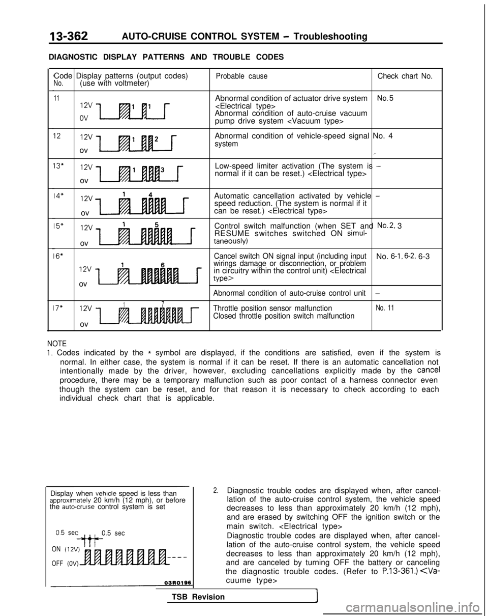
DIAGNOSTIC DISPLAY PATTERNS AND TROUBLE CODES Code Display patterns (output codes)
No.(use with voltmeter)
11
xJa-.tu
Probable causeCheck chart No.
Abnormal condition of actuator drive systemNo.5
Abnormal condition of auto-cruise vacuum
pump drive system
1212vAbnormal condition of vehicle-speed signal No. 4systemov/
13"12vLow-speed limiter activation (The system is -normal if it can be reset.)
ov
14*12v14Automatic cancellation activated by vehicle -speed reduction. (The system is normal if it
ov can be reset.)
15"12v15Control switch malfunction (when SET and No.2, 3
RESUME switches switched ON simul-
ovtaneously)
16"Cancel switch ON signal input (including inputNo. 6-1, 6-2. 6-3
12v16wirings damage or disconnection, or problemin circuitry within the control unit)
we>
Abnormal condition of auto-cruise control unit-
17"12v17Throttle position sensor malfunctionNo. 11
Closed throttle position switch malfunction
ov
NOTE
1. Codes indicated by the * symbol are displayed, if the conditions are satisfied, even if the system is
normal. In either case, the system is normal if it can be reset. If ther\
e is an automatic cancellation not
intentionally made by the driver, however, excluding cancellations explicitly made by the
cancel
procedure, there may be a temporary malfunction such as poor contact of \
a harness connector even
though the system can be reset, and for that reason it is necessary to c\
heck according to each individual check chart that is applicable.
ON
OFF
-
Display when vehicle speed is less thanapproximately 20 km/h (12 mph), or before
the auto-cruise control system is set
0.5 set
++P5 setDiagnostic trouble codes are displayed when, after cancel-
lation of the auto-cruise control system, the vehicle speed
decreases to less than approximately 20 km/h (12 mph),
and are canceled by turning OFF the battery or canceling
the diagnostic trouble codes. (Refer to
P.13-361.)
TSB Revision
2.Diagnostic trouble codes are displayed when, after cancel-
lation of the auto-cruise control system, the vehicle speed
decreases to less than approximately 20 km/h (12 mph),
and are erased by switching OFF the ignition switch or the
main switch.
Page 506 of 1273
13-364AUTO-CRUISE CONTROL SYSTEM - Troubleshooting
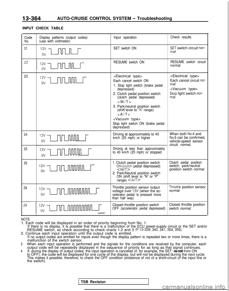
INPUT CHECK TABLE
Code Display patterns (output codes) Input operationCheck resultsNo.(use with voltmeter)
21SET switch ONSmE,: switch circuit nor-
RESUME switch ON RESUME switch circuit
normal
23
Each cancel switch ONEach cancel circuit nor-
1. Stop light switch (brake pedalmal
depressed)
2. Clutch pedal position switch(clutch pedal depressed)
St;p light switch nor-
3. Park/neutral position switch
(shift lever to “N” range)
>
Stop light switch ON (brake pedal
depressed)
24
25
n r
Driving at approximately to 40 When both No.4 and
km/h (25 mph) or higherNo.5 can be confirmed,
vehicle-speed sensor
circuit normal.
n r
Driving at less than approximately
to 40 km/h (25 mph) or stopped
26I. Clutch pedal position switchsNJFy;h pedal depressed)
2. Park/Neutral position switch
ON (shift lever to “N” or “P”
range)
Clutch pedal positionswitch, park/neutral position switch normal
28Throttle position sensor output
voltage over 1.5V (when the ac-celerator pedal is pressed more
than half way)
$yro;e position sensor
Closed throttle position switch Closed throttle position
OFF (accelerator pedal depressed)switch normal
NOTE1. Each code will be displayed in an order of priority beginning from No\
. 1.If there is no display, it is possible that there is a malfunction of th\
e ECU power-supply circuit or the SET and/orRESUME switch, so check according to check charts 1.2 and 3 (P.13-339,340,341,354,355).2. Continue each input operation until the output code is emitted.If no output codes are emitted for inputs even though the display patter\
n is repeated two or more times, there is amalfunction of the switch sensor.3.When each input operation is performed and the signals for the condition\
s are received by the computer, eachoutput code will be repeatedly displayed in the sequence of priority for\
as long as that signal continues.4.If, during the display of output codes, the input operation is canceled \
(if, for example, the SET switch is set from ONto OFF), the code will be displayed for one cycle of the display, but w\
ill not be displayed during the next cycle.This makes it possible, therefore, to check the OFF condition (existenc\
e of not of a short-circuit of the input line orthe switch).
TSB Revision
Page 508 of 1273
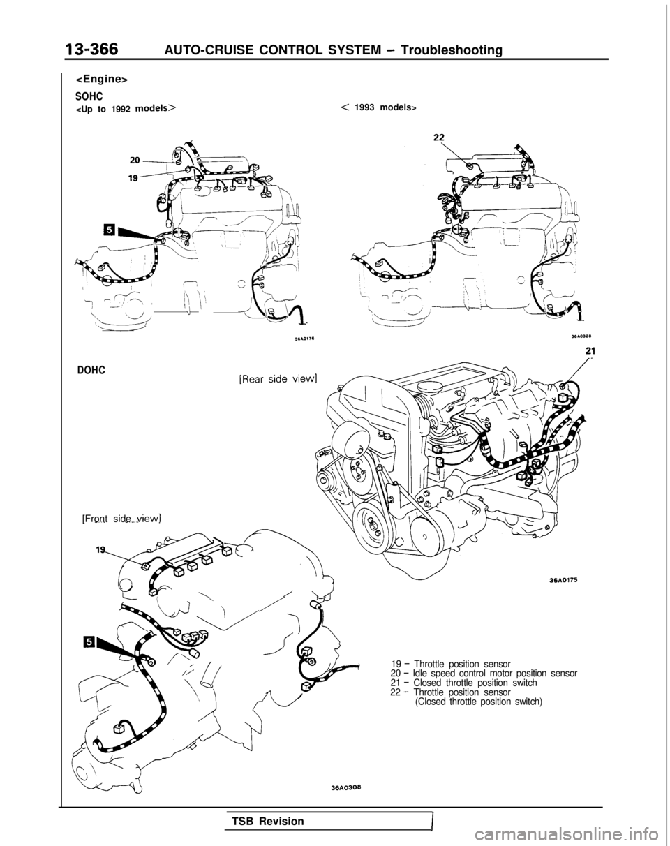
13-366AUTO-CRUISE CONTROL SYSTEM - Troubleshooting
SOHC
w ,-,’<:
z
\ ‘8.-.-,‘I\ 1:FI ‘iiI -I \’1: j\\dd
/T&Jq
< 1993 models>
DOHC
[Front side view1-.._ -.-- ~
l’e‘--
??A-
‘LA
\\/’ w 36AO175
19 - Throttle position sensor
20 - Idle speed control motor position sensor
21 - Closed throttle position switch
22 - Throttle position sensor (Closed throttle position switch)
36AO303
TSB RevisionI