Page 435 of 1273
FUEL SYSTEM -On-Vehicle Inspection of MFI Components13-293
HEATED OXYGEN SENSOR M13YSAAa
sensor connector
\ \
6FU1425
2
d6
25E
gt;a,W
TheoreWal A/F
14
15
16 A/F
EC1007
OPERATION
TROUBLESHOOTING HINTS INSPECTION-Using Scan tool
Refer to P.1.3-290.
HARNESS INSPECTION
connector Heated oxygen
sensor ComDonent
side
Multiport fuel
injection relay
Engine control module
Engine control module connector @
Harness side
connector
6FU1628
OlLO838
Measure the power supply voltage of
the heated oxygen sensor.
Connector: DisconnectedIgnition switch: O
N
,
TSB Revision
Page 436 of 1273
13-294FUEL SYSTEM -On-Vehicle Inspection of MFI Components
L
21
@ ~~kn~~nnector -
@
m
4 3
~
gPEngine
control mod&harness sideconnector
@ Harness sideconnector
6FU1545
41Harness side@ connector
,1
”
m
/Y
L/-- 0
I
&00
Enginecontrol moduleharness sideconnector
If*-L- 6FU154.5
Check for an open-circuit or a short-
circuit to ground, between the engine
control module and the heated oxy-gen sensor.
. Heated oxygen sensor connec-tor: Disconnected. Engine control module connec-tor: Disconnected Repair the-+ harness.
Check for continuity of the groundcircuit.
. Connector: Disconnected
cl4
Repair theharness.
RzsEl-llosl)
Check for an open-circuit or a short-
circuit to ground, between the engine
control module and the heated oxy-gen sensor.
. Heated oxygen sensor connec- tor: Disconnected
. Engine control module connec- tor: Disconnected
SENSOR INSPECTlON
Refer to P.13-292.
1 TSB Revision
lASTOP
Repair the+ harness.
h23xl--11051)
Page 437 of 1273
FUEL SYSTEM -On-Vehicle Inspection
of
MFI
Components13-295
Filter
Connector
Solenoid coil
Plunger
Needle valve -&$
lnjedtion6FUO51
Multiport
fuel injection relayMIBvrbA1
I
The area enclosed with ~~~~ is@I Harness side
applicable onlv for Turbo.
connector
Enginecofitrolmodule
Engine control module connectorI6FU1547
OlLo63
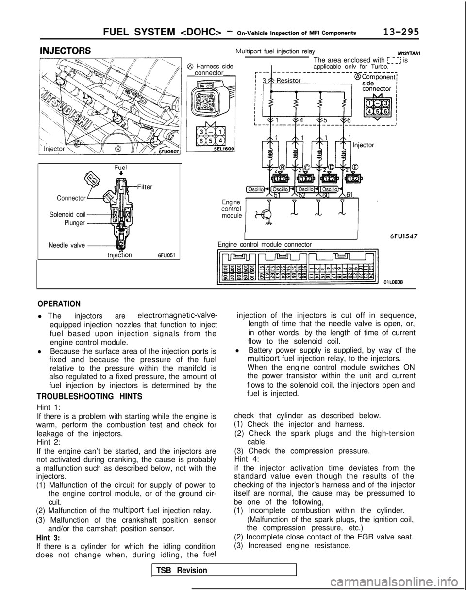
OPERATION
l The injectorsare electromagnetic-valve-
equipped injection nozzles that function to inject
fuel based upon injection signals from the engine control module.
lBecause the surface area of the injection ports is
fixed and because the pressure of the fuel relative to the pressure within the manifold is
also regulated to a fixed pressure, the amount of
fuel injection by injectors is determined by the
TROUBLESHOOTING HINTS
Hint 1:
If there is a problem with starting while the engine is
warm, perform the combustion test and check for leakage of the injectors.Hint 2:
If the engine can’t be started, and the injectors are
not activated during cranking, the cause is probably
a malfunction such as described below, not with the injectors.
(1) Malfunction of the circuit for supply of power to
the engine control module, or of the ground cir-
cuit.
(2) Malfunction of the multiport fuel injection relay.
(3) Malfunction of the crankshaft position sensor and/or the camshaft position sensor.
Hint 3:
If there is a cylinder for which the idling condition
does not change when, during idling, the fuelinjection of the injectors is cut off in sequence,
length of time that the needle valve is open, or,
in other words, by the length of time of current
flow to the solenoid coil.
lBattery power supply is supplied, by way of the
multiport fuel injection relay, to the injectors.
When the engine control module switches ON
the power transistor within the unit and current
flows to the solenoid coil, the injectors open and
fuel is injected.
check that cylinder as described below.
(1) Check the injector and harness.
(2) Check the spark plugs and the high-tension
cable.
(3) Check the compression pressure. Hint 4:
if the injector activation time deviates from the
standard value even though the results of the
checking of the injector’s harness and of the injector
itself are normal, the cause may be pressumed to
be one of the following,
(1) Incomplete combustion within the cylinder.
(Malfunction of the spark plugs, the ignition coil,
the compression pressure, etc.)
(2) Incomplete close contact of the EGR valve seat.
(3) Increased engine resistance.
TSB Revision
Page 457 of 1273
FUEL SYSTEM -
On-Vehicle
Inwection of MFI
ComDonents13-315
INSPECTION OF ENGINE CONTROL MODULE
TERMINAL VOLTAGEM13zALCa
Refer to P.13-105.
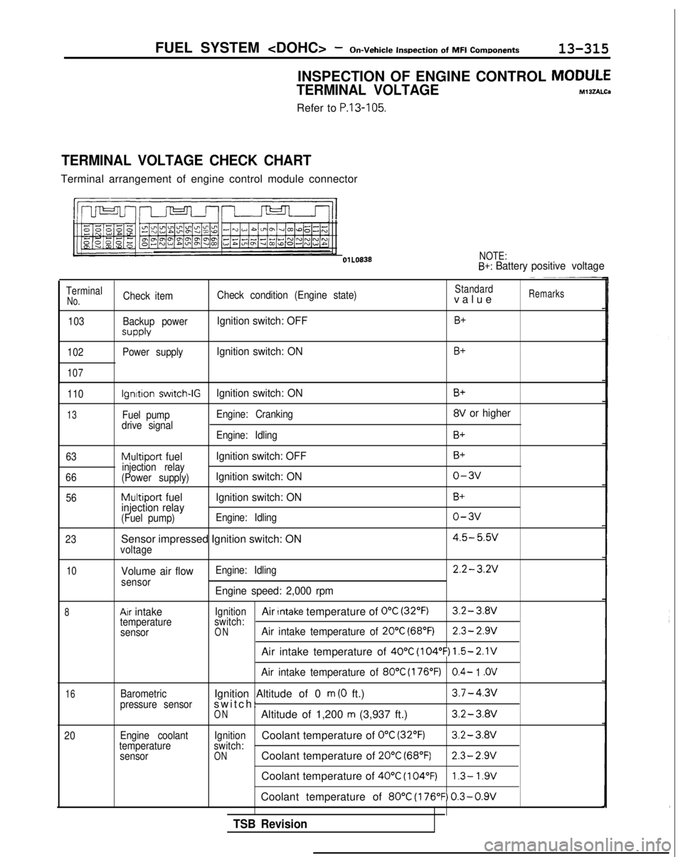
TERMINAL VOLTAGE CHECK CHART
Terminal arrangement of engine control module connector
l!m n-J-J-l-II
NOTE:B+: Battery
positive voltage
TerminalCheck item Check condition (Engine state)Standardvalu
e
Remarks
No.
103
102
107
Backup power
SUPPlY
Power supply
Ignition switch: OFFB+
Ignition switch: ONB+
110
13
63
66 56
23
Ignition switch-IGIgnition switch: ON
Fuel pump Engine: Cranking
drive signal Engine: Idling
Multiport fuel Ignition switch: OFFinjection relay
(Power supply)Ignition switch: ON
Multiport fuel Ignition switch: ON
injection relay
(Fuel pump) Engine: Idling
Sensor impressed Ignition switch: ONvoltage
B+
8V or higher
B+
B+
o-3v
B+
o-3v
4.5- 5.w
10
8
16
20
Volume air flowsensor
Ax intaketemperature
sensor
Barometric
pressure sensor
Engine coolant
temperature sensor Engine: Idling
2.2-3.2V
Engine speed: 2,000 rpm
IgnitionAir Intake temperature of 0°C (32°F)3.2- 3.8V
switch:
ONAir intake temperature of 20°C (68°F)2.3- 2.9V
Air intake temperature of 40°C (104°F) 1.5-2.1V
Air intake temperature of 80°C (176°F)0.4- 1 .OV
Ignition Altitude of 0 m (0 ft.)3.7-4.3v
switch
:
ONAltitude of 1,200 m (3,937 ft.)3.2-3.8V
IgnitionCoolant temperature of 0°C (32’F)3.2-
3.Wswitch:ONCoolant temperature of 20°C (68°F)2.3- 2.9V
Coolant temperature of 40°C (104°F)1.3- 1.9V
Coolant temperature of 80°C (176°F) 0.3-0.9V
TSB Revision
Page 458 of 1273
13-316FUEL SYSTEM -On-Vehicle
Inspection
of
MFI
Components
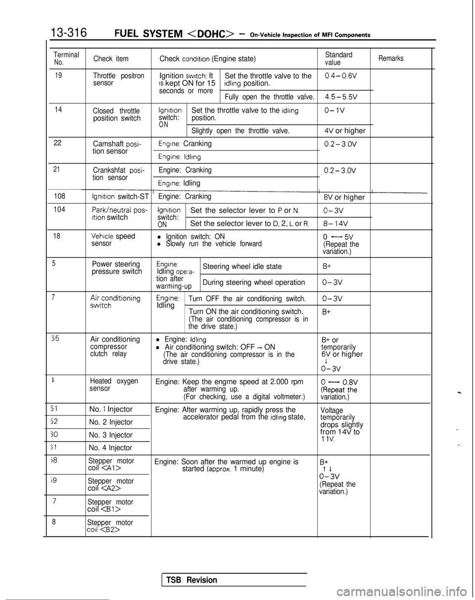
TerminalNo.Check itemCheck condition (Engine state)Standardvalue
Remarks
19Throttle positronIgnition switch: ItSet the throttle valve to the0.4- 0.wsensorIS kept ON for 15seconds or moreidlrng position.
Fully open the throttle valve.4.5- 5.5v
14
Closed throttlelgnrtrono-1vposition switchswitch:Set the throttle valve to the idling
position.
ONSlightly open the throttle valve.4V or higher
22Camshaft posi-tion sensorEngine: Cranking0.2- 3.ov
Engine: ldlrng
21
Crankshfat posi-tion sensor Engine: Cranking0.2- 3.ov
Engine: Idling
108lgnrtion switch-STEngine: Cranking8V or higher
104
Park/neutral
pos-ition switchIgnitionSet the selector lever to P or N.o-3vswitch:ONSet the selector lever to D, 2, L or R.8- 14V
18Vehicle speedl Ignition switch: ON
sensorl Slowly run the vehicle forward0 - 5v(Repeat the
variation.)
5Power steering
pressure switchEngine:Idling opera-Steering wheel idle stateB+
tion afterwarming-upDuring steering wheel operationo-3v
7A&;;;ditioningEngine:Idling _Turn OFF the air conditioning switch.o-3v
Turn ON the air conditioning switch.B+
(The air conditioning compressor is in
the drive state.)
35Air conditioningl Engine: IdlingB+ orcompressor
clutch relayl Air conditioning switch: OFF -, ON(The air conditioning compressor is in the
temporarily
drive state.)6V or higher o’-
3v
1Heated oxygen
sensorEngine: Keep the engrne speed at 2.000 rpmafter warming up.
(For checking, use a digital voltmeter.)ke;atoZivariation.)
51No. 1 InjectorEngine: After warming up, rapidly press the
52No. 2 Injector accelerator pedal from the idlrng state,Voltage
temporarily
drops slightly
30No. 3 Injectorfrom 14V to1 IV.
51No. 4 Injector
j8
Stepper motorcoil Engine: Soon after the warmed up engine isB+started (approx. 1 minute)
i9
Stepper motor0%
coil (Repeat the
variation.)
‘7Stepper motorcoil
8Stepper motorco11
TSB Revision
Page 459 of 1273
FUEL SYSTEM -On-Vehicle
Inspection
of MFI
Components13-317
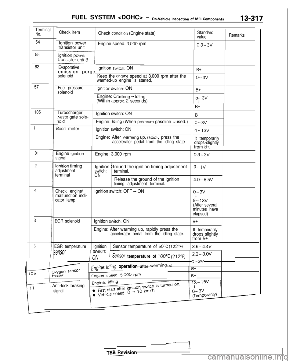
TerminalNo.
54
55
62
57
105
I
01
2
i
E
Check item
Ignition power
transistor unit Check
condition (Engine state)
Engine speed:
3.000 rpm
Standardvalue
0.3- 3v
Remarks
Evaporativeemission purgeIgnition switch: ONB+
solenoidKeep the engrne speed at 3.000 rpm after thewarmed-up engine is started,o-3v
Fuel pressure
solenoidlgnltlon switch: ON
Engine:
Cranking - Idling(Within approx. 2 seconds)
B+
o- 3v1
B+
TurbochargerNaste gate sole-Ignition switch: ONB+ ioid
Engine: Idling (When premrum gasoline IS used.)0-3~
3oost meter
Ignition switch: ON4-13v
Engine: After warming up, rapldly press theaccelerator pedal from the idling state It temporarily
drops-slightlyIfrom B+.
Engine ignrtlonslgnalEngine: 3,000 rpm0.3-3v
lgnrtion timingadjustment
terminalIgnition Ground the ignition timing adjustment 0- 1Vswitch:terminal.ONRelease the ground of the ignition4.0- 5.5vtiming adjustment terminal.
Check engine/
malfunction indi- Ignition switch: OFF - ONo-3v
cator lamp9’- 13v(After several
minutes have
elapsed)
EGR solenoidIgnition switch: ONB+
Engine: After warming up, rapidly press theaccelerator pedal from the idling state. It temporarilydrops slightly
from B+.
EGR temperatureIgnitionSensor temperature of 50°C (122’F)3.6- 4.4V
rSt?MX
I
swlrcrl:nhir--.%?nY/V-_. ..sof temperature of 100°C (21.20~)2.2-3.0~
Engine: Idling operation after warming
UP
o-3v
B+
Engine &ed: 5.000 rPmB+
\ Anti-lock braking
signal
TSR Revision-
-
‘i
Page 462 of 1273
13-320FUEL SYSTEM - Fuel Tank
03RO297
V/apor hose
mmin.)
3FOO7
Filler
hoseB
A
Flare nut
\Secure side 03YO43
Ll
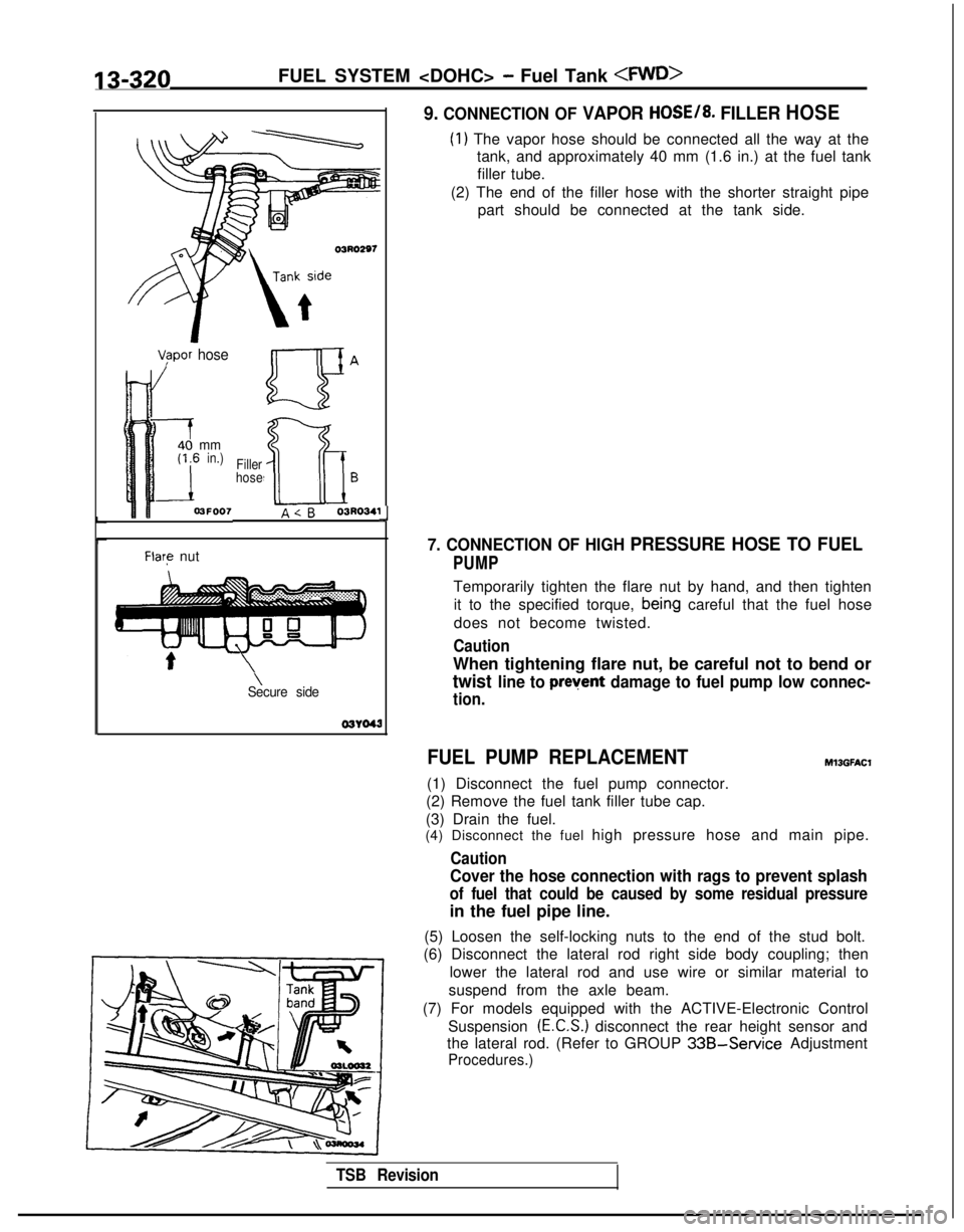
9. CONNECTION OF VAPOR HOSE/8. FILLER HOSE
(1) The vapor hose should be connected all the way at the
tank, and approximately 40 mm (1.6 in.) at the fuel tank
filler tube.
(2) The end of the filler hose with the shorter straight pipe part should be connected at the tank side.
7. CONNECTION OF HIGH PRESSURE HOSE TO FUEL
PUMP
Temporarily tighten the flare nut by hand, and then tighten
it to the specified torque,
bein,g careful that the fuel hose
does not become twisted.
Caution
When tightening flare nut, be careful not to bend or
twist line to prevent damage to fuel pump low connec-
tion.
FUEL PUMP REPLACEMENT
(1) Disconnect the fuel pump connector.
(2) Remove the fuel tank filler tube cap.
(3) Drain the fuel.
Ml3GFAt.X
(4) Disconnect the fuel high pressure hose and main pipe.
Caution
Cover the hose connection with rags to prevent splash
of fuel that could be caused by some residual pressure
in the fuel pipe line.
(5) Loosen the self-locking nuts to the end of the stud bolt.
(6) Disconnect the lateral rod right side body coupling; then
lower the lateral rod and use wire or similar material to
suspend from the axle beam.
(7) For models equipped with the ACTIVE-Electronic Control Suspension
(E.C.S.) disconnect the rear height sensor and
the lateral rod. (Refer to GROUP
33B-Service Adjustment
Procedures.)
TSB Revision
Page 463 of 1273
FUEL SYSTEM - Fuel Tank 13-321
I03LOO18
-
QGB ua \
a=
C-CT
0a
c oc3i20’0Qaa
Positidning projection
03L0000
(8) Remove the fuel pump installation screws and the bolt for
holding the fuel pump (at the lower side of the fuel tank),
and then remove the fuel pump from the fuel tank.
(9) Align the three positioning projections of the packing with the holes in the fuel pump.
(lO)When the fuel pump is installed, the holding bolt at the
lower side of the fuel tank should be installed first. Care should be taken at this time that the O-ring is not
pinched.
(1 l)For models equipped with the ACTIVE-E.C.S., check the operation of the ACTIVE-E.C.S. after installation of the rear
height sensor. (Refer to GROUP
33B-Service Adjustment
Procedures.)