Page 407 of 1273
FUEL SYSTEM -On-Vehicle Inspection of MFI Components13-265
>
Volume air flow sensor
side connector
I J
1
I
6FUO62:-I
r
rature sensor
TSB Revision
:Turbo>
lerature sensor,$kpntak _-.-.- --
i\PJtemp -
-“, ’
w\
SENSOR INSPECTION
(1) Disconnect the volume air flow sensor connectors.
(2) Measure resistance between terminals @ and @.
(3)
Er$%e resistance between terminals @ and 0,.
Temperature “C (“F)
0 (32)
20 (68)
80 (176)
Resistance (kQ)
6.0
2.7
0.4
(3) Measure resistance while heating the sensor using a hair
drier.
Temperature “C (“F)
Higher
Resistance (kR)
Smaller
(4) If the value deviates from the standard value or the resist- ance remains unchanged, replace the volume air flow sen-
sor assembly.
Page 408 of 1273
13-266FUEL SYSTEM - On-vehicle Inspection of MFI Components
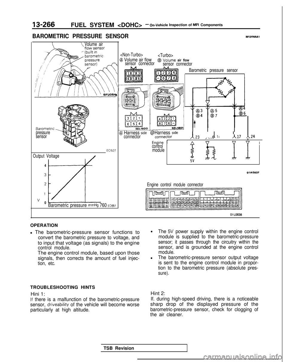
BAROMETRIC PRESSURE SENSORMl3VHPYPl
\ Volume air
Barometric
pressure
sensor
Output Voltage
/-4
3
2
1
v 0LzLBarometric pressure mmHg 760 ~~1551
EC1537
(
7
\
‘i
6!
I
I1(
B Volume air flow@ Volume air flowsensor connector sensor connector
5EL1600, L-@I Harness sideconnector@Harness sidernnn~rtnr131 11, I ’““, ,. Iv-.-.,\L4 ,\-5A17 h24
Fnnine 1Anv uI
Barometric pressure sensor
-“J -control
module
I
OllO537
Engine control module connector
01 LOB38
OPERATION
l The barometric-pressure sensor functions to
convert the barometric pressure to voltage, and
to input that voltage (as signals) to the engine
control module.
The engine control module, based upon those
signals, then corrects the amount of fuel injec-
tion, etc.
TROUBLESHOOTING HINTS Hini 1:
If there is a malfunction of the barometric-pressure
sensor,
driveability of the vehicle will become worse
particularly at high altitude.
lThe 5V power supply within the engine control
module is supplied to the barometric-pressure
sensor; it passes through the circuitry within the
sensor, and is grounded at the engine control
module.
lThe barometric-pressure sensor output voltage is sent to the engine control module in propor-
tion to the barometric pressure (absolute pres-
sure).
Hint 2:
If. during high-speed driving, there is a noticeable
sharp drop of the displayed pressure of the
barometric-pressure sensor, check for clogging of
the air cleaner.
TSB Revision
Page 409 of 1273
FUEL SYSTEM -On-Vehicle inspection of MFI Components13-267
INSPECTION
Using Scan tool
Function Item No.
Data display
Data reading
25Sensor detec-tion pressure
HARNESS INSPECTION
Check conditions1 Altitude1 Standard value
lanltion switch: ON1 At 0 m (0 ft.)LrnmmHq
At 600 m(1,969 ft.)710 mmHg
At 1,200 m660 mmHg(3,937 ft.)
At I:800
m610 mmHg
(5,906 ft.)
. Connector:Disconnected
Measure the power supply voltage Ofthe barometric pressure sensor.
connector
TSB Revision
-Engine controlmodule harness
side connector
6%
-
Check for an open-circuit, or a shqrt-circuit to ground, between the enginecontrol module and the barometricpressure sensor.
. Volume air flow sensor connec-tor: Disconnected@--/LA
- Engine control module connec-tor: Disconnected
Page 410 of 1273
13-26813-268FUEL SYSTEM -FUEL SYSTEM -On-Vehicle Inspection of MFI Components
On-Vehicle Inspection of MFI Components
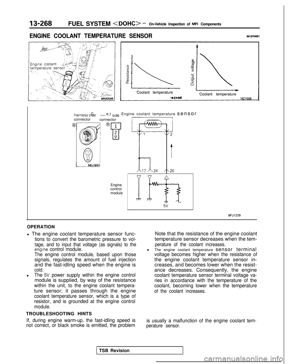
ENGINE COOLANT TEMPERATURE SENSOR
ENGINE COOLANT TEMPERATURE SENSORMl3YIABlMl3YIABl
Coolant temperature
Coolant temperature 1ez4sa
Coolant temperature
Coolant temperature
16210081621008
t+arness s,de C
ompone
nt side
Engine coolant temperature sensorIconnector
connectori- ,
Jr
Engine
control module
Ih5v
6FU1239
OPERATION
l The engine coolant temperature sensor func-
tions to convert the barometric pressure to vol-
tage, and to input that voltage (as signals) to the
engine control module.
The engine control module, based upon those signals, regulates the amount of fuel injection
and the fast-idling speed when the engine is
cold.
lThe 5V power supply within the engine control
module is supplied, by way of the resistance
within the unit, to the engine coolant tempera-
ture sensor; it passes through the engine
coolant temperature sensor, which is a type of
resistor, and is grounded at the engine control
module.
TROUBLESHOOTING HINTS
If, during engine warm-up, the fast-idling speed is
not correct, or black smoke is emitted, the problem
Note that the resistance of the engine coolant
temperature sensor decreases when the tem-
perature of the coolant increases.
l The engine coolant temperature sensor terminal
voltage becomes higher when the resistance of
the engine coolant temperature sensor in-
creases, and becomes lower when the resist-
ance decreases. Consequently, the engine
coolant temperature sensor terminal voltage va-
ries in accordance with the temperature of the
coolant, becoming lower when the temperature
of the coolant increases.
is usually a malfunction of the engine coolant tem-
perature sensor.
TSB Revision
Page 411 of 1273
1 V-L “IVILI.,. ““I ,“Ivn-ven,c,e lnsprcrlorl 91
l”lb-l b”mp”nerlrrI” L””
INSPECTION
Using Scan tool
FunctionItem No.Data display Check conditionsCoolant temperatureStandard value
Data reading
2 1Sensor de-Ignition switch: ONAt -20°C
(-4°F)- 20°CtectionOr, engine running
temperatureAt 0°C (32°F)0°C
At 20°C (68°F)20°C
At 40°C (104°F)40°C
At 80°C (176°F)80°C
HARNESS INSPECTION
@ Harnesssideconnector
OlL0463
connector
OlL0461
Check for continuity of the groundcircuit.
. Connector: Disconnected
Measure the power supply voltage.
. Connector: Disconnected. Ignition switch: ON
IVoltage (V)
4.5-4.9
SENSOR INSPECTION (1) Remove engine coolant temperature sensor from the
intake manifold.
(2) With temperature sensing portion of engine coolant
temperature sensor immersed in hot water check resist-
ance.
Temperature “C V’F)Resistance (kQ)
‘0(32)5.9
20(68)2.5
40
(104)1.1
80(176)0.3
(3) If the resistance deviates from the standard value greatly replace the sensor.
TSB Revision
Page 412 of 1273
13-270FUEL SYSTEM - On-Vehicle inspection of MFI Components
INSTALLATION
(1) Apply sealant 3M NUT locking No.4171 or
equivalent to threaded portion.
(2) Install engine coolant temperature sensor and
tighten it to specified torque. Sensor tightening
torque:
20-40 Nm (15-29 ft.lbs.1
(3) Fasten harness connectors securely.
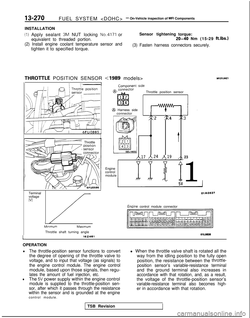
THROlTLE POSITION SENSOR M13YJAEl
F” Throttle
Terminal
voltage
WI
//-L/:MInimumMaxlmum
Throttle shaft turning angle
162461
ComDonent side
Throttle position sensor @
Harness side
connector
I
;:2 %4 :
0
t
~17 ~24 /,19 ,
Engine
control module23
1 Enqine
control module connector
01L0838L
OPERATION
lThe throttle-position sensor functions to convert
the degree of opening of the throttle valve to
voltage, and to input that voltage (as signals) to
the engine control module. The engine control
module, based upon those signals, then regu-
lates the amount of fuel injection, etc.
lThe 5V power supply within the engine control
module is supplied to the throttle-position sen-
sor, after which it passes through the resistance
within the sensor and is grounded at the engine
control module. l When the throttle valve shaft is rotated all the
way from the idling position to the fully open
position, the resistance between the
throttle-
position sensor’s variable-resistance terminal
and the ground terminal also increases in
accordance with that rotation, and, as a result,
the voltage of the throttle-position sensor’s
variable-resistance terminal also becomes high-
er in accordance with that rotation.
TSB Revision
Page 413 of 1273
FUEL SYSTEM - On-Vehicle Inspection of MFI Components13-271
TROUBLESHOOTING HINTS
Hint 1:
The signals of the throttle-position sensor are more
important for control of the automatic transaxle than
for control of the engine; shifting “impact shocks”
are produced if there is a malfunction of the
throttle-position sensor.
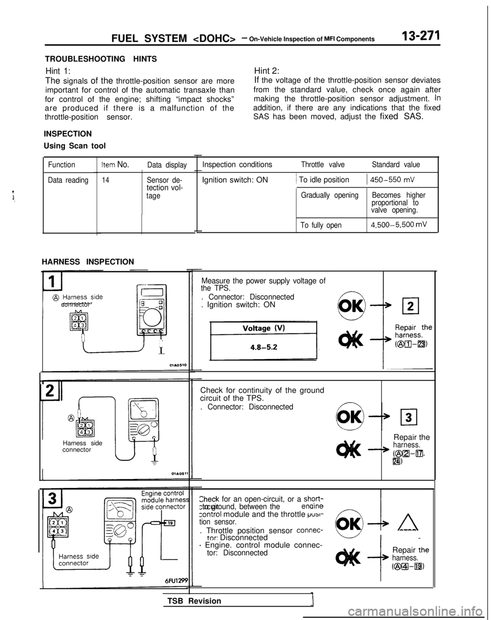
INSPECTION
Using Scan tool Hint 2:
If the voltage of the throttle-position sensor deviates
from the standard value, check once again after making the throttle-position sensor adjustment.
in
addition, if there are any indications that the fixedSAS has been moved, adjust the fixed SAS.
Function
Data readingItem No.Data display
14Sensor de-tection vol-
tage
HARNESS INSPECTION
connector
Harness side
connector
Inspection conditionsThrottle valve Standard value
Ignition switch: ON/ To idle position1 450-550
mV
Gradually opening Becomes higher
proportional to
valve opening.
To fully open 4,500-5,500
mV
Measure the power supply voltage of
the TPS.
. Connector: Disconnected
. Ignition switch: ON
Check for continuity of the ground
circuit of the TPS.
. Connector: Disconnected
Repair theharness.
+ K25xz.l-~~IZI)
LZheck for an open-circuit, or a shqrt-Yrcuit to ground, between the er-.--control module and the throttle ~USI-tion sensor.
. Throttle position sensor connec-tnr: Disconnected I
-
- Engine. control module connec-tor: DisconnectedRepair theharness.
u23Bl-m)
TSB Revision
Page 414 of 1273
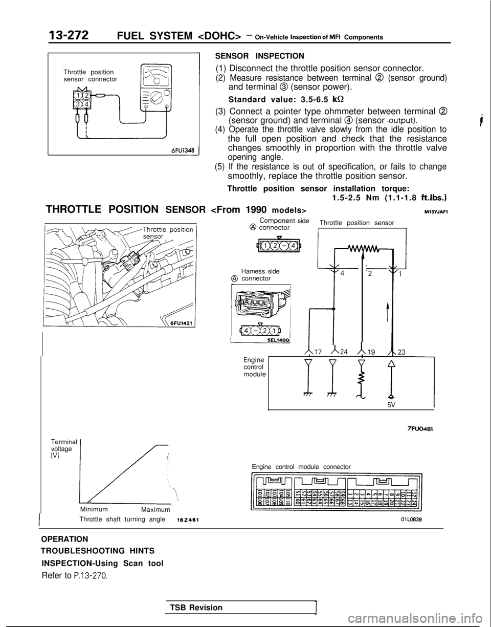
13-272FUEL SYSTEM - On-Vehicle inspection of MFI Components
Throttle position sensor connector
6FU1348-i
SENSOR INSPECTION
(1) Disconnect the throttle position sensor connector.
(2) Measure resistance between terminal @ (sensor ground)
and terminal @ (sensor power).
Standard value: 3.5-6.5 kR
(3) Connect a pointer type ohmmeter between terminal
@
(sensor ground) and terminal @ (sensor .output).
(4) Operate the throttle valve slowly from the idle position to
the full open position and check that the resistance changes smoothly in proportion with the throttle valve
opening angle.
(5) If the resistance is out of specification, or fails to change
smoothly, replace the throttle position sensor.
Throttle position sensor installation torque: 1.5-2.5 Nm (1.1-1.8
ftlbs.)
THROTTLE POSITION SENSOR MlSYJAFl
LTerminal
voltage
WI(;
LL “-*:,Minimum
Maximum
Throttle shaft turning angle
162461 @
connkctor ComDonent
side
Throttle position sensorI
4
-I
Harness side$I connector
/t17 A24 Ar--'--crlylriecontrol
module
7FUO481
Engine control module connector
OPERATION
TROUBLESHOOTING HINTS
INSPECTION-Using Scan tool
Refer to P.13-270.
i,
TSB Revision