Page 358 of 1273
13216FUEL SYSTEM - Troubleshooting
CIRCUIT DIAGRAM (CONTINUED)
< 1989 models>
KTROLIGNITION POWER MFIUNIT TRANSISTORRELAY
,nr ,nrc n TD CT nv c!crw.fl\“l.I”mL c)I‘\ IAl””ULtll”JR"/\2
,PTAKB *,A VOLUkz! FLOWIBOR
1.25-R
LI: CRANKSHAFT1 POSITION SENSORg AND CAMSHAFT
. POSITION SENSORa
A-57
\//1 I,t“3"5"4 "6 "1‘$1 '"3*54
t5Gk3s 6mI
z3m1,
WI
wm=-i !QIIII1*I
z-l t
' I
- ____-- J,-----3 I
m
ENGINE
%%&TURE
A-55 m“‘3
1 “&a,. YYI..d”..73 nnLxD-C”OXYGEN SENSORCHECK CONNECTOR
B c-14KX35-AC-H052SA-NY
TSB Revision
Page 363 of 1273
FUEL SYSTEM - Troubleshooting
13-221
AY!&&ROLUNITMFIRELAY
$1r 1.25-R a
Y
z
VOLUME AIR FLOW SENSORI s
:CRANKSHAFT
POSITION
ZEWM;;ON
I\
A-47IYIAKC AIR VDLUIO!.ZCYPLRA’T”RE AIR ?LW
IEI
BCYBOR BLR8OR1es166
Ly,34
a
I
2-----1,21t%TROL UNIT
0SV5V
A-57
OXYGEN SENSORCHECK CONAIECTOR
KX35-AC-HOWA-NY
TSB Revision
Page 368 of 1273
13-226
FUEL SYSTEM - Troubleshooting
CIRCUIT DIAGRAM (CONTINUED)
< 1990 models (Non-turbo)>
MFIRELAY0
vD:
a
I
z s1.25-R10
mVOLUME AIR FLOW SENSOR",,2
lNT.RP AIR
VOLUYLTLYPRRIWRl AIR ?LWP.L”SDP BUISOR
"3"5"4 "6 "1
%Gs
s
$
l
CRANKSHAFTPOSITIONsNJl&+m
i=;=&;;ON
A-47
A-57
22I:------21!&TROL UNIT
$85V5V
-r
m
II I
I
!
I
I
I e
L
OXYGEN SENSORCH,ECK CONNECTOR
KX35-AC-HOS3Sb-NM
TSB Revision
1
Page 369 of 1273
FUEL SYSTEM - Troubleshootina13-227
IDLE AIR ,,25CONTROL
MOTOR
B-03 cMllea
m "1PS \,456
::
EVAPOR; TIVE
T T7
i?ii 781
k.1 CQMBINATIONq 31
I"
(ENG)
(DATA)
DATA LINKCONNECTOR
C-18 %
FRONT SIDE
5v
+3---__-- ----------------_
11
i
12
2
IGNITIONTIMINGADJUSTMENTCONNECTOR
B-04
f&l
A-61EGR TEMERATURE
@SENSOR
(VEHICLES FOR
CALIFORNIA)
Page 373 of 1273
FUEL SYSTEM - Troubleshooting13-231
4:
;zs1.25-R10
'1;rOLUK!Z AIR FLOW SENSOR
ANDA-47
12
m
I1221 t%TE!OL UNI
T
“? I@ 1 Yi Y
qEqsrp---~--~g---[~---------;;-~4 iuY&ii’------
1 mi mi E I
wT”ill’li
I II’-1 q-1’ I
f I I IT-11 I l-ijdrnl &$$$I I
i IIIII
z III
a
2 1
0
KNOCK
u
SENSOR
EII WI- CLiiEDdTHROTTLE =ENGINE
COOLANTTHROTTLE-l'#;&ON
##@ATURE @&ONB-22-2mEl %HEATED
OXYGEN SENSOR
1
1iB-04-1
B-02 Il!dB-02-1-B-20OXYGEN SENSORg@ e
CHECK CONNECTOR
m c-14H
l-
L
xX35-Ac-n0537wiu
,
TSB RevisionI
Page 378 of 1273
13-236FUEL SYSTEM - Troubleshooting
CIRCUIT DIAGRAM (CONTINUED)
MFIRELAY
9c
z
s1.25-RT0r
IKTA‘E AIR VDLUYEEWEPATMBAIn ?LovEJEYBOR 8ElBORAND
r
%hROL
UNIT
tiNDV“G” w b
~“l~-l~~106~~~-~~~---~~~-
:A.mi cw?%4,<,
-,L
4)
I I
3 IIm
2 1
h--+-PC
KNOCK
SENSOR
B-04-1
I-
B-20 -OXYGEN GENSORw :
CHECK CONNECTOR
TSB Revision
Page 390 of 1273

13-248FUEL SYSTEM - Service Adjustment Procedures
(8) Switch OFF the ignition switch.
(9) If the scan tool was not used, disconnect the jumper wire from the diagnostic test mode control terminal. (10)Disconnect
the jumper wire from the terminal for adjust-
ment of ignition timing, and return the connector to its
original condition.
(11
)Start the engine again and let it run at idle speed for about
ten minutes; check to be sure that the idling condition is
normal.
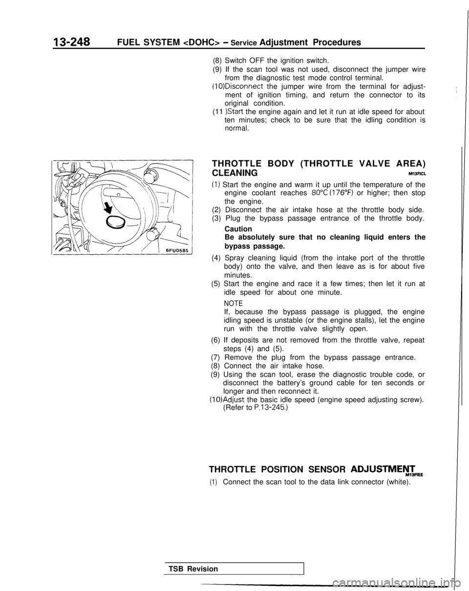
THROTTLE BODY (THROTTLE VALVE AREA)
CLEANING
Ml3ACL
(1) Start the engine and warm it up until the temperature of the engine coolant reaches
80°C (176°F) or higher; then stop
the engine.
(2) Disconnect the air intake hose at the throttle body side.
(3) Plug the bypass passage entrance of the throttle body.
Caution
Be absolutely sure that no cleaning liquid enters the
bypass passage.
(4) Spray cleaning liquid (from the intake port of the throttle body) onto the valve, and then leave as is for about five
minutes.
(5) Start the engine and race it a few times; then let it run at
idle speed for about one minute.
NOTE
If, because the bypass passage is plugged, the engine
idling speed is unstable (or the engine stalls), let the engine
run with the throttle valve slightly open.
(6) If deposits are not removed from the throttle valve, repeat steps (4) and (5).
(7) Remove the plug from the bypass passage entrance.
(8) Connect the air intake hose.
(9) Using the scan tool, erase the diagnostic trouble code, or disconnect the battery’s ground cable for ten seconds or
longer and then reconnect it. (lO)Adjust
the basic idle speed (engine speed adjusting screw).
(Refer to
P.13-245.)
THROTTLE POSITION SENSOR ADJUSTMEyTmEE
(1)Connect the scan tool to the data link connector (white).
TSB Revision
Page 391 of 1273

FUEL SYSTEM - Service Adjustment Procedures
13-249
<1989 models> /zz Throttle position
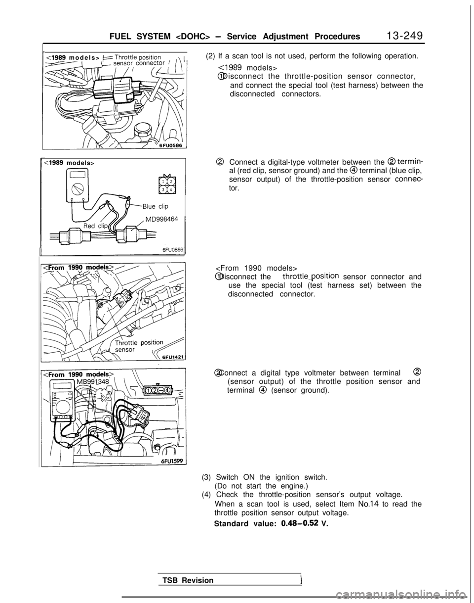
(2) If a scan tool is not used, perform the following operation.,-
~1989 models> @ Disconnect the throttle-position sensor connector,
and connect the special tool (test harness) between the
disconnected connectors.
:1989 models>@Connect a digital-type voltmeter between the @ termin-
al (red clip, sensor ground) and the @I terminal (blue clip,
sensor output) of the throttle-position sensor connec-
tor.
Blue
clip
@ Disconnect the
throttle.position sensor connector and
use the special tool (test harness set) between the
disconnected connector. @ Connect a digital type voltmeter between terminal @
(sensor output) of the throttle position sensor and
terminal
@ (sensor ground).
(3) Switch ON the ignition switch. (Do not start the engine.)
(4) Check the throttle-position sensor’s output voltage.
When a scan tool is used, select Item
No.14 to read the
throttle position sensor output voltage.
Standard value:
0.48-0.52 V.
TSB Revision
I