Page 393 of 1273
Page 394 of 1273
13-252FUEL SYSTEM - On-Vehicle Inspection of MFI Components
Heated oxygen sensor
la&/+$&,s ‘T*
1 \‘!;/ *- 7)lY-7
\ I--.P--&O596I ~~
- ~~~- ,,od&>/ ‘I.! m
”<1989 Ilgnltlon co11 (Ignition:
Dower transistor).\ [
TSB Revision
Page 396 of 1273
13-254FUEL SYSTEM - On-Vehicle Inspection of MFI ComponentsVehicle
speed sensor
adjustment terminal
- check terminal ---
-
II
,
Turbocharger
waste gate
a,ylenoid
‘I K&h--
=yq@
control module
1 TSB Revision
Page 397 of 1273

FUEL SYSTEM - On-Vehicle Inspection of MFI Components13-255
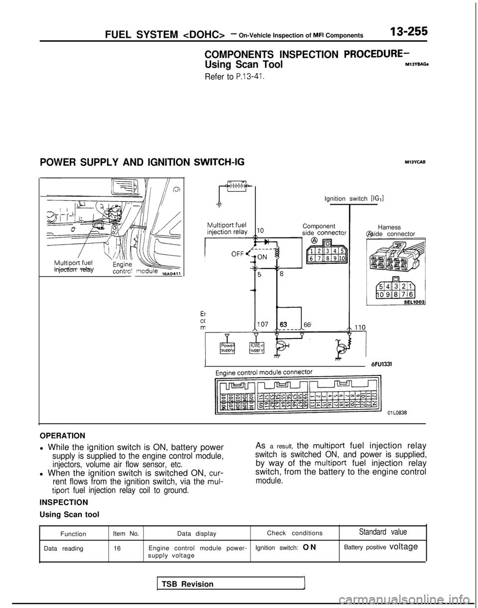
COMPONENTS INSPECTION PROCEDURE-
Using Scan ToolMlsYsAGa
Refer to P.13-41.
POWER SUPPLY AND IGNITION SWITCH-IG
zT=f?Qjkeinjection relay
contrc! qcdule ,6A04,,-
----_OFF/ (IN
t5
’ i
4
-
‘OWE;uppl-
Ignition switch [IG,]
Component
side
connect<
763 66.----
1 6FU1331, )r
Ml3YcAB
Harness
@ side connector
01 LO838
OPERATION
l While the ignition switch is ON, battery power
supply is supplied to the engine control module,
injectors, volume air flow sensor, etc.
l When the ignition switch is switched ON, cur-
rent flows from the ignition switch, via the mul-
tiport
fuel injection relay coil to ground.
INSPECTION
Using Scan tool As a result, the
multiport fuel injection relay
switch is switched ON, and power is supplied,
by way of the multiport fuel injection relay
switch, from the battery to the engine control
module.
Function
Data reading Item No.
Data display Check conditionsStandard value
16
Engine control module power- Ignition switch: O
N
Battery positive voltage
supply voltage
TSB Revision I
Page 403 of 1273

FUEL SYSTEM -On-Vehicle inspection of MFI Components13-261
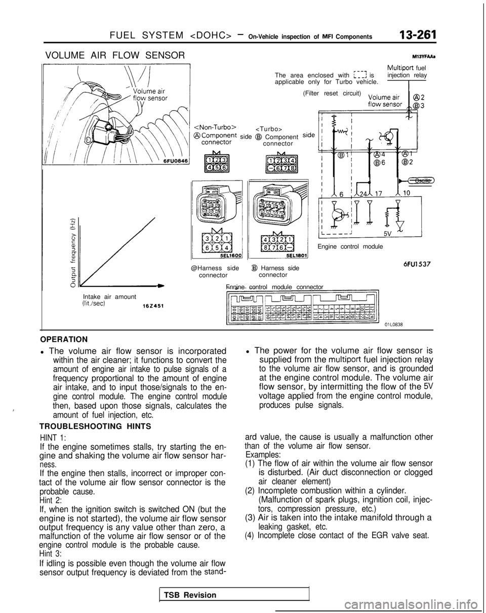
VOLUME AIR FLOW SENSORMlWFAAs
/
side
@Harness side connector
I@ Harness sideconnector
Fnnine control module connector
Multiport fuel
The area enclosed with :I: is injection relay
applicable only for Turbo vehicle.
I
@I Component connector (Filter reset circuit)
Engine control module
6FU1537
Intake air amount (Wsec)
162451
OlLO838
OPERATION
l The volume air flow sensor is incorporated
within the air cleaner; it functions to convert the
amount of engine air intake to pulse signals of a
frequency proportional to the amount of engine air intake, and to input those/signals to the en-
gine control module. The engine control module
then, based upon those signals, calculates the
amount of fuel injection, etc.
TROUBLESHOOTING HINTS
HINT 1:
If the engine sometimes stalls, try starting the en-
gine and shaking the volume air flow sensor har-
ness.
If the engine then stalls, incorrect or improper con-
tact of the volume air flow sensor connector is the
probable cause.
Hint 2:
If, when the ignition switch is switched ON (but the
engine is not started), the volume air flow sensor
output frequency is any value other than zero, a
malfunction of the volume air flow sensor or of the
engine control module is the probable cause.
Hint 3:
If idling is possible even though the volume air flow
sensor output frequency is deviated from the
stand-
l The power for the volume air flow sensor is supplied from the
multiport fuel injection relay
to the volume air flow sensor, and is grounded
at the engine control module. The volume air
flow sensor, by intermitting the flow of the
5V
voltage applied from the engine control module,
produces pulse signals.
ard value, the cause is usually a malfunction other
than of the volume air flow sensor. Examples:
(1) The flow of air within the volume air flow sensor
is disturbed. (Air duct disconnection or clogged
air cleaner element)
(2) Incomplete combustion within a cylinder.(Malfunction of spark plugs, ingnition coil, injec-
tors, compression pressure, etc.)
(3) Air is taken into the intake manifold through a
leaking gasket, etc.
(4) Incomplete close contact of the EGR valve seat.
TSB Revision
Page 404 of 1273

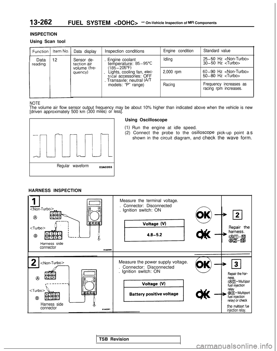
13-262FUEL SYSTEM - On-Vehicle Inspection of MFI Components
INSPECTION
Using Scan tool
1 Data 12reading
L
Data displayInspection conditions
Sensor de-. Engine coolanttection airtemperature: 85-95°Cvolume (fre-(185-205°F)quency) .Lights, cooling fan, elec-trical accessories: OFF. Transaxle: neutral (PJTmodels: “P” range)
Engine condition
Idling
2,000 rpm
Racing
Standard value 25-50
Hz 30-50 Hz
60-90 Hz 50-80 Hz
Frequency increases as
racing rpm increases.
NOTEThe volume air flow sensor output frequency may be about 10% higher than\
indicated above when the vehicle is new
[driven approximately 500 km(300 miles) or less].
i
Regular waveform03AO203
HARNESS INSPECTION Using Oscilloscope
(1) Run the engine at idle speed.
(2) Connect the probe to the osilloscope
pick-up point as
shown in the circuit diagram, and check the wave form.
Measure the terminal voltage.
. Connector: Disconnected
. Ignition switch: ON
connectorOlMaa
Measure the power supply voltage.
. Connector: Disconnected
. Ignition switch: ON
Harness side
connectorthe multiport fueinjection relay.
TSB Revision
Page 405 of 1273
FUEL SYSTEM - On-Vehicle Inspection of MFI Components13-263
Check for continuity of the ground
circuit of the VAF sensor.
. Connector: Disconnected
\--connector
4Harness side Check for continuity between the
en-3 air__.. --.. ..-gine control moduie and volumt
UIIflow sensor.Y---L1 A
. Engine control module connec-
tor: Disconnected- Volume air flow sensor connec-tor: Disconnected
kTOA
Repair theharness.
NliwHBl)
DlAO!XO
MlJYGAAlUTAKE AIR TEMPERATURE SENSORI
I
Temperature-Temperature1621008
142454
-
sensor connector , Intake air temperature sensorIntake air
temperature sensor
I24
Intake air
@I Harness side
connector@I Harness side
.8.I
4Enginecontrol
module 5V
I1
6FU1298
Iv---I1 TSB Revision
Page 406 of 1273

13-264FUEL SYSTEM - On-Vehicle Inspection of MFI Components
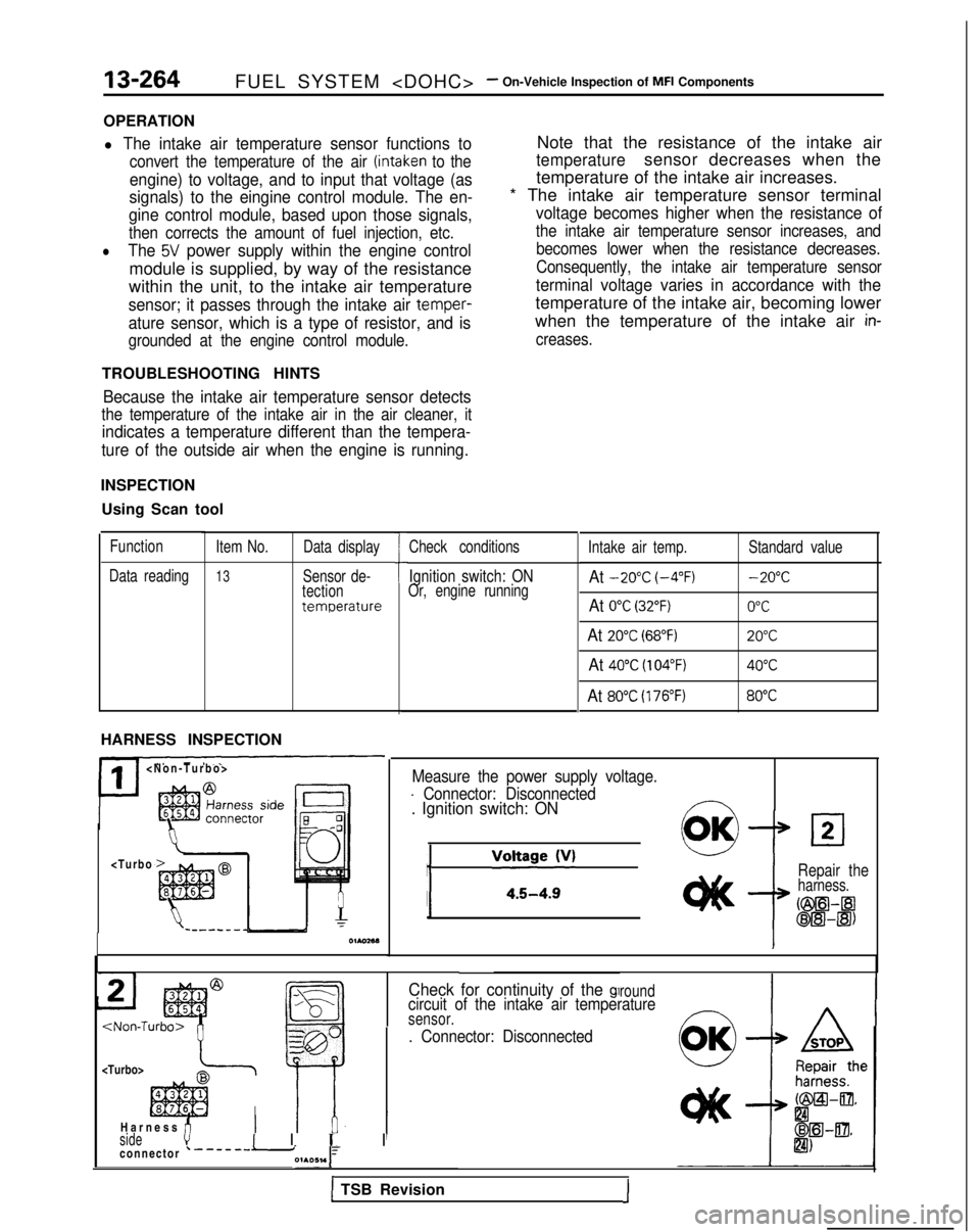
OPERATION
l The intake air temperature sensor functions to
convert the temperature of the air (intaken to the
engine) to voltage, and to input that voltage (as
signals) to the eingine control module. The en-
gine control module, based upon those signals,
then corrects the amount of fuel injection, etc.
lThe 5V power supply within the engine control
module is supplied, by way of the resistance
within the unit, to the intake air temperature
sensor; it passes through the intake air temper-
ature sensor, which is a type of resistor, and is
grounded at the engine control module.
Note that the resistance of the intake air
temperaturesensor decreases when the
temperature of the intake air increases.
* The intake air temperature sensor terminal
voltage becomes higher when the resistance of
the intake air temperature sensor increases, and becomes lower when the resistance decreases.
Consequently, the intake air temperature sensor
terminal voltage varies in accordance with the
temperature of the intake air, becoming lower
when the temperature of the intake air
in-
creases.
TROUBLESHOOTING HINTS
Because the intake air temperature sensor detects
the temperature of the intake air in the air cleaner, it
indicates a temperature different than the tempera-
ture of the outside air when the engine is running.
INSPECTION
Using Scan tool
Function
Data reading Item No.
13
Data display
Sensor de-
tection
temperature
HARNESS INSPECTION
II
>
7 7
h
I
Check conditions
Ignition switch: ONOr, engine running
Intake air temp.At -20°C (-4°F)
At 0°C (32°F)
At 20°C (68°F)
At 40°C (104°F)
At 80°C (176°F)
Standard value -20°C
0°C
20°C
40°C
80°C
Measure the power supply voltage.
- Connector: Disconnected. Ignition switch: ON
j
/‘“:;~~~v’0OKLl2
Repair theharness.
Cm--a
oE!l-@)
Check for continuity of the glroundcircuit of the intake air temperaturesensor.
. Connector: Disconnected
I
sidevI I 1~ I
I
Harness fi
connector ‘-------i01A051.1
1 TSB Revision1