Page 415 of 1273

FUEL SYSTEM -On-Vehicle inspection of MFI Components13-273
@ Harness srdeconnector
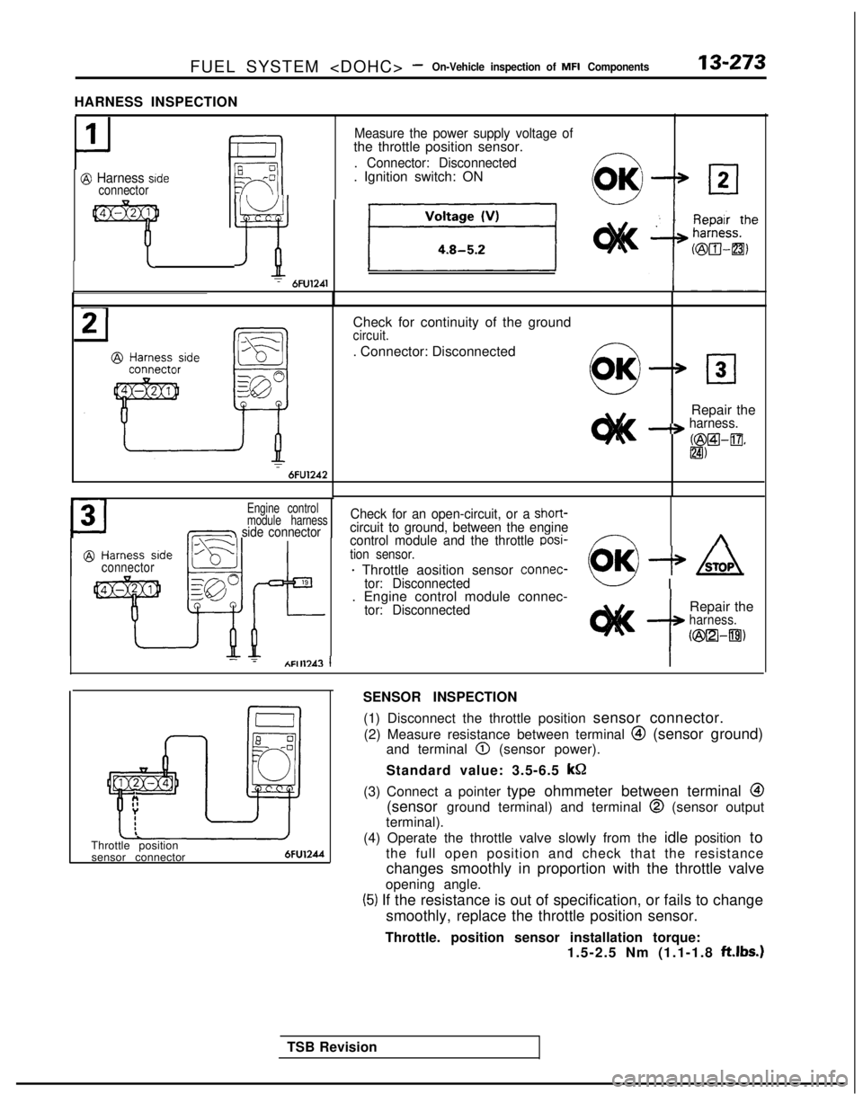
HARNESS INSPECTION
1
II
Measure the power supply voltage ofthe throttle position sensor.
. Connector: Disconnected. Ignition switch: ON-
~ LfEf piziq
6FU1241
Check for continuity of the groundcircuit.
. Connector: Disconnected
Repair the
-+ harness. R2Wl-a*
IZI)T6FU1242
Engine control
module harness
~=YY=zY=~ side connector
connector
?IAFIll 1
TSB Revision
Check for an open-circuit, or a short-circuit to ground, between the engine
control module and the throttle oosi-Y---YAtion sensor.
+ Throttle aosition sensor connec-(OK) + /sroa\
tor: Disconnectedk-l I
. Engine control module connec-
tor: Disconnected
i
Repair theharness.
k%lmBl)
SENSOR INSPECTION
(1) Disconnect the throttle position sensor connector.(2) Measure resistance between terminal
@ (sensor ground)
and terminal
0 (sensor power).
Standard value: 3.5-6.5 kQ
(3) Connect a pointer type ohmmeter between terminal
@
(sensor ground terminal) and terminal @
(sensor output
terminal).
Throttle position sensor connector
6FU124d
(4) Operate the throttle valve slowly from the idle position to
the full open position and check that the resistance changes smoothly in proportion with the throttle valve
opening angle.
(5) If the resistance is out of specification, or fails to change
smoothly, replace the throttle position sensor.
Throttle. position sensor installation torque: 1.5-2.5 Nm (1.1-1.8
ft.lbs.1
Page 416 of 1273

13-274FUEL SYSTEM - On-Vehicle Inspection of MFI Components
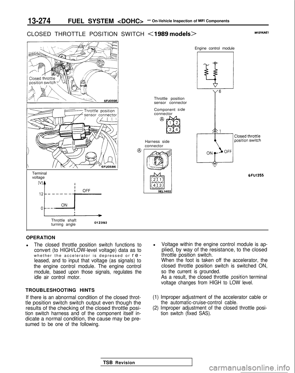
CLOSED THROTTLE POSITION SWITCH
MlSYKAEl
Terminal
voltage
Throttle shaft
turning angle Engine control module
1
Throttle position
sensor connector
Component side
connector
Harness side
connector
6FU1355
OPERATION
l
The closed throttle position switch functions to
convert (to HIGH/LOW-level voltage) data as to
whether the accelerator is depressed or re
-
leased, and to input that voltage (as signals) to
the engine control module. The engine control
module, based upon those signals, regulates the
idle air control motor.
TROUBLESHOOTING HINTS
If there is an abnormal condition of the closed throt-
tle position switch switch output even though the results of the checking of the closed throttle posi-
tion switch harness and of the component itself in-
dicate a normal condition, the cause may be pre-
sumed to be one of the following.
lVoltage within the engine control module is ap-
plied, by way of the resistance, to the closed
throttle position switch.
When the foot is taken off the accelerator, the
closed throttle position switch is switched ON,
so the current is grounded.
As a result, the closed throttle .position terminal
voltage changes from HIGH to LOW level.
(1) Improper adjustment of the accelerator cable or
the automatic-cruise-control cable.
(2) Improper adjustment of the closed throttle posi-
tion switch (fixed SAS).
TSB Revision
Page 417 of 1273
FUEL SYSTEM - On-Vehicle Inspection of MFI Components13-275
INSPECTION
Using Scan tool
Function
Item No.
Data reading 26
Data displayInspection conditions Throttle valveNormal indication
Switch statusIgnition switch: ONTo idle positionON(Check after pumpingaccelerator several times.)
Slightly openedOFF
HARNESS INSPECTION
71
-
Harness side
Measure the power supply voltage of
the closed throttle position switch.
-. Connector: Disconnected
. Ignition switch: ON
1Voltage (VI
4 or more
ASTOP
Repair theharness.
~@a-Q)
ISENSOR INSPECTION
I(1) Disconnect the throttle position senso_r connector
(2) Check the continuity between terminal QI and body ground.
TSB Revision
Accelerator pedal Continuity
DepressedNon-conductive (m S2)
ReleasedConductive (0 52)
(3) If out of specification, replace the throttle position sensor
assembly.
Page 418 of 1273
13-276FUEL SYSTEM -On-Vehicle Inspection of MFI Components
CLOSED THROTTLE POSITION SWITCH
Termrnalvoltage
Throttle shaft
turning angle012092
a
1
Closed throttle
position switch
terminal Engine control module
ci
Closed throttle
position switch
6FU13 56
OPERATION
TROUBLESHOOTING HINTS INSPECTION-Using Scan toolRefer to
P.13-274.
HARNESS INSPECTIONL
P
1
I
:
I @ Harness side
connector
Closed throttle
position switch
terminal
L
Measure the power supply voltage of
the closed throttle position switch.
. Connector: Disconnected
. Ignition switch: ON
SENSOR INSPECTION(1) Disconnect the closed throttle position switch connector.
(2) Check the continuity between terminal
@I and sensor
ground.
IAccelerator pedalIContinuityI
IDepressedINon-conductive (a Q)I
ReleasedConductive (0 S2)I
(3) If out of specification, replace the closed throttle position
switch.
TSB Revision
Page 419 of 1273

FUEL SYSTEM -On-Vehicle Inspection of MFI Components13-277
CAMSHAFT POSITION SENSOR Multiport fuelM13Yuh
1 Output characteristic
I-cTime
One rotation of crankshaft position sensor injection relay
Component side Crankshaft
connector position sensor
2I14,
Crankshaft
position
sensor
connector
I_ /
i7; !
~\==, ’60,Giiz!! @ Harness side
connector Camshatt posItIon
sensor
Engine control module
A22
Q
6FU1255
OPERATION
l The camshaft position sensor functions to de-
tect the top dead center position of the No.1 cy-
linder and to convert those data to pulse signals
that are input to the engine control module. The
engine control module, based upon those sig-
nals, calculates the sequence of fuel injection.
TROUBLESHOOTING HINTS
If there is a malfunction of the camshaft position
sensor, the sequential injection will not be correct,
lThe power for the camshaft position sensor is
supplied from the multiport fuel injection relay
and is grounded to the vehicle body. The cam-
shaft position sensor, by intermitting the flow (to
ground) of the 5V voltage applied from the en-
gine control module produces pulse signals.
resulting in such problems as engine stalling, un-
stable idling, and poor acceleration.
5v---r-
ovL_--..---I2 --
Normal waveform INSPECTION
Using Oscilloscope
(1) Run the engine at an idle speed.
(2) Connect the probe to the oscilloscope pick-up point as
shown in the circuit diagram, and check the waveform.
Page 421 of 1273
FUEL SYSTEM -On-Vehicle Inspection of MFI Components13-279
CAMSHAFT POSITION SENSOR M13YlABl
@
Component side
connector
Output characteristic
WINo.45
) Time
One rotation of crankshaft position sensor
Multiport fuel
injection relay
Crankshaft position sensor
I3
Engine control module
7FUO493
OPERATION
TROUBLESHOOTING HINTS INSPECTION-Using Oscilloscope Refer to
P.13-277.
HARNESS INSPECTION
Harness side
connector Measure the power supply voltage.
. Connector: Disconnected
. Ignition switch: ON
7FUO496
TSB Revision
Page 422 of 1273
13-280FUEL SYSTEM -On-Vehicle Inspection of MFI Components
2
rHarness side
connector @
-----.
m
l----L
=s- 0
H
z/Q
=
7FVO497
P
3@ Harness srdeconnectorE 0
-0
4
0
c
7FVO498
Check for continuity of the ground
circuit.
. Connector: Disconnected
Repair theharness.
@WGround)
Check the output circuit voltage.
. Connector: Disconnected
. Ignition switch: ON
IVoltage (V)
1 4.8-5.2 (
CRANKSHAFT POSITION SENSOR
v] ) Output characteristic
LIaTime - One
rotation of crankshaft position sensor
OlROlO3
Multiport fuel
injection relay @
Component side Crankshaft position
connector @
Harness side
), 27Engine control module
MIOYYAAI
TSB Revision
Page 423 of 1273

FUEL SYSTEM - On-Vehicle Inspection of MFI Components13-281
OPERATION
l
The crankshaft position sensor functions to de-
tect the crank angle (position) of each cylinder,
and to convert those data to pulse signals,
which are then input to the engine control mod-
ule. The engine control module, based upon
those signals, calculates the engine rpm, and
also regulates the fuel injection timing and the
ignition timing.
TROUBLESHOOTING HINTS
Hint 1:
If an impact is suddenly felt during driving or the en-
gine suddenly stalls during idling, try shaking the
crankshaft position sensor during idling.
If the engine stalls, the cause may be presumed to
be improper or incomplete contact of the crank-
shaft position sensor’s connector.
Hint 2:
If the crankshaft position sensor output rpm is 0
rpm during cranking when the engine cannot be
started, the cause may be presumed to be a mal-
function of the crankshaft position sensor or a bro-
ken timing belt.
Hint 3:
If the indicated value of the crankshaft position sen-
sor output rpm is 0 rpm during cranking when the
engine cannot be started, the cause may be pre-
INSPECTION
Using Scan tool l
The power for the crankshaft position sensor is
supplied from the ignition switch-IG
and is
grounded to the vehicle body. The crankshaft
position sensor, by intermitting the flow (to
ground) of the 5V voltage applied from the en-
gine control module, produces pulse signals.
sumed to be a failure of the ignition coil’s primary
current to intermittently pulse correctly, so a mal-
function of the ignition system circuitry, the ignition
coil and/or the power transistor is the probable
cause. Hint 4:
If idling is possible even though the crankshaft posi-
tion sensor indicated rpm is a deviation from the
standard value, the cause is usually a malfunction of
something other than the crankshaft position sen-
sor.
Examples:
(1) Malfunction of the coolant-temperature sensor.
(2) Malfunction of the idle air control motor.
(3) Improper adjustment of the standard idling
speed.
Inspection conditions
Description Normal condition
. Engine: CrankingCompare crankingBoth agree.. Tachometer connectionrpm and scan tool(Check intermittent flow ofindicated rpm.ignition coil primary current
by tachometer.)
burn No. / ~i~~~~,,Inspection conditions
At 40°C (104°F)
At 80°C (176°F)
1 ,OOO- 1,250 rpm
650-850 rpm 700-900 mm
>
TSB Revision
I