Page 551 of 1273
Page 553 of 1273

14-1
COOLING
ENGINE COOLANT TEMPERATURE GAUGE
UNIT, ENGINE COOLANT
TEMPERATURE SENSOR AND ENGINE
COOLANT TEMPERATURE
SWITCH.............
31
RADIATOR ....................................................... 9
RADIATOR FAN MOTOR ASSEMBLY ..........
12
SERVICE ADJUSTMENT PROCEDURES..
.....
8
Engine Coolant Concentration Test .............
8
Engine Coolant LeakCheck
........................8
Engine Coolant
Replacement .......................
8
Radiator Cap Pressure Test .........................
8
SPECIAL TOOL................................................5
SPECIFICATIONS .............................................
2
General Specifications ..................................
2
Lubricant
....................................................... 4
CONTENTS
IM14AA-
Sealant. . . . . . . . . . . . . ..__...........’ . . . . . . . . . . . . . \
. . . . . .._.........4
ServiceSpecifications . . . . .. . . . . . . . . . . . . . . . . . . . . . . . . . . . .2
Torque
Specifications. . . . . . . . . . . . . . . . . . . . . . . . . . . . . . . . . . .3
THERMOSTAT. . . . . . . . . . . . . . . . . . . . . . . . . . . . . . . . . . . . \
. . . . . . . . . . . . .13
TROUBLESHOOTING. . . . . . . . . . . . . . . . . . . . . . . . . . . . . . . . . . . . \
. .5
No rise in temperature
Overheat
WATER HOSE AND WATER PIPE
. . . . . . . . . . . . . . . . . . . . . . . . . . . . . . . . . . .26
WATER HOSE AND WATER PIPE
. . . . . . . . . . . . . . . . . . . . . . . . . . . . . . . . . . . . . . . . . . .28
WATER HOSE AND WATER PIPE
>
. . . . . . . . . . . . . . . . . . . . .
. . . . . . . . . . . . . . . . . . . . . . . . . . . . . ..a.....23
WATER PUMP
. . . . . . . . . . . . . . . . . . . . . . . . . . . . . . .20
WATER PUMP
. . . . . . . . . . . . . . . . . . . . . . . . . . . . . . .15
Page 554 of 1273

14-2
COOLING- Specifications
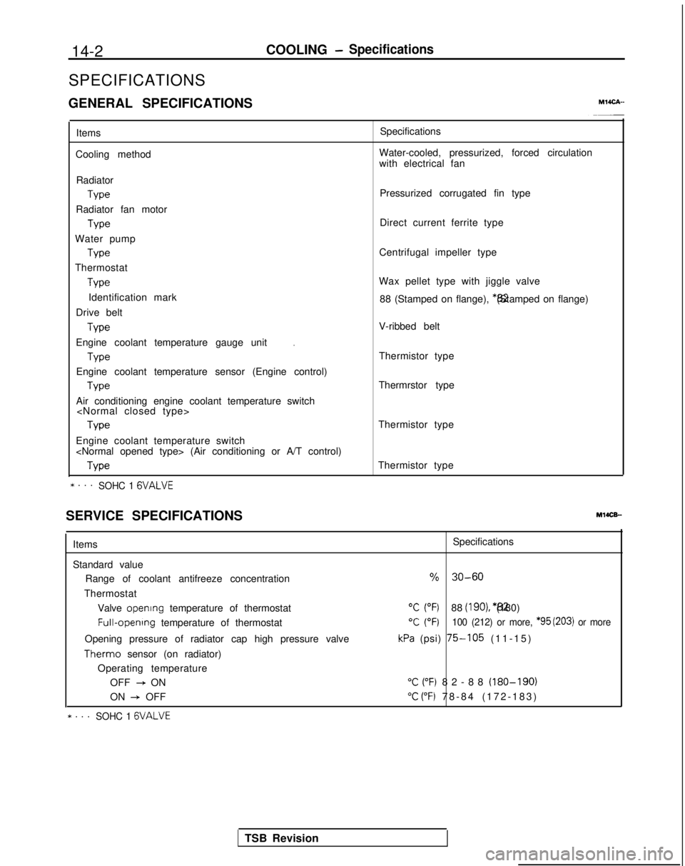
SPECIFICATIONS
GENERAL SPECIFICATIONS
MlICA-
Items
Cooling method Specifications
Water-cooled, pressurized, forced circulation
with electrical fan
Radiator Type
Radiator fan motor Type
Water pump Type
Thermostat Type
Identification mark
Drive belt Type
.Engine coolant temperature gauge unit
Type
Engine coolant temperature sensor (Engine control) Type
Air conditioning engine coolant temperature switch Type
Engine coolant temperature switch
(Air conditioning or A/T control) Type
* . . .SOHC 1 GVALVE
Pressurized corrugated fin type
Direct current ferrite type
Centrifugal impeller type
Wax pellet type with jiggle valve 88 (Stamped on flange), *82 (Stamped on flange)
V-ribbed belt
Thermistor type
Thermrstor type
Thermistor type
Thermistor type
SERVICE SPECIFICATIONS
MlOCB-
Items
Standard value Range of coolant antifreeze concentration
Thermostat Valve opening
temperature of thermostat Full-opening
temperature of thermostat
Opening pressure of radiator cap high pressure valve Therm0
sensor (on radiator)
Operating temperature OFF
+ ON
ON
+ OFF
* . . .SOHC 1 GVALVE
Specifications
% 30-60
“C (“F)88 (IgO), *82 (180)
T (OF)100 (212) or more, *95 (203) or more
kPa (psi) 75-105 (11-15
)
“C (“F) 82-88 (180-190)
“C (“F) 78-84 (172-183
)
TSB Revision
Page 555 of 1273

COOLING- Specifications14-3
Items Specifications
Engine coolant temperature gauge unit ResistanceAt
70°C (158°F)n 104f13.5
Engine coolant temperature sensor (Engine control) ResistanceAt
20°C (68°F)kQ 2.45 f 0.24
At 80°C (176°F)Q 296+32
Air conditioning engine coolant temperature switch
ON
+ OFF operating temperature“C (“F) 112-118 (234-244
)
Engine coolant temperature switch
(Air conditioning or A/T control)
OFF
+ ON operating temperature“C (“F) 100-104 (212-219
)
Limit
Opening pressure of radiator cap high pressure valvekPa (psi) 65 (9.2)
TORQUE SPECIFICATIONS
MWCG-
ItemsNm ft.lbs.
Radiator upper insulator 9-14
7-10
Reserve tank, bracket installation bolt9-1
4
7-10
Thermosensor to radiator35
25
Automatic transaxle oil coole: hose cramp 4-
6
3-4
Automatic transaxle oil cooler hose mounting bolt 3-5
2-4
Water outlet fitting bolts
17-2012-14
Water inlet fitting bolts
IO-157-10
Engine mount insulator nut (large)60-8043-58
Engine mount insulator nut (small)
\ 30-4022-29
Engine mount bracket to engine
50-6536-47
Bracket between engine mount bracket and engine 17-26
12-19
Water pump installation bolt Bolt head mark “4T”
12-15
9-l 1
Bolt head mark “7T”20-2714-20
dater pump pulley bolt8-106-
7
Jamper pulley, crankshaft pulley20-3014-22
Timing belt front upper cover installation bolt
IO-127-
9
Timing belt front lower cover installation bolt
IO-127-
9
Crankshaft
sprocket installation bolt
110-13080-94
Timing belt B tensioner 15-2211-16
Tension pulley bracket for air conditioning
23-2717-20
Automatic tensioner installation bolt20-2714-20
Tensioner pulley installation bolt43-5531-40
Oil level gauge 12-159-l 1
Front exhaust pipe to exhaust manifold
40-5029-36.
30-4022-29
Front exhaust pipe bracket
30-4022-29
Exhaust manifold cover (A), (B)
12-15
9-11
Heat protector 12-159-11
TSB Revision
Page 556 of 1273

14-4COOLING-Specifications
Items
Exhaust manifold to cylinder head
< 1993 models>
>
Engine hanger to engine bracket
Oxygen sensor
Water inlet pipe installation bolt Transaxle side
Engine block side
< 1993 models>
Engine coolant temperature gauge unit
Engine coolant temperature sensor (Engine control)
Air conditioning engine coolant temperature switch
Engine coolant temperature switch
(Air conditioning or A/T control) Rocker cover installation bolt
Exhaust manifold to turbocharger
Eye bolt (oil pipe)
Air outlet fitting installation bolt
Water pipe
B
Front exhaust pipe to turbocharger
Eye bolt (water pipe)
Water pipe
B clamp
Oil return pipe
Water hose installation bolt
Nater hose to turbocharger
Ixhaust pipe support bracket
Exhaust pipe support bracket to front exhaust pipe Nm ft.lbs.
15-2011-14
25-3018-22
27-3320-23
25-3018-22
12-15 9-11
40-5029-36
43-55
31-40
IO-157-10
12-15 9-11
IO-127-
9
20-4014-29
30-4022-29
IO-148-10
5-
7
4-5
55-65
40-47
14-19IO-14
9-1
4
7-10
40-5029-36
40-6029-43
35-5025-36
IO-127-
9
8-106-
7
12-15 9-11
IO-127-
9
8-106-
7
30-4222-30
30-4022-29
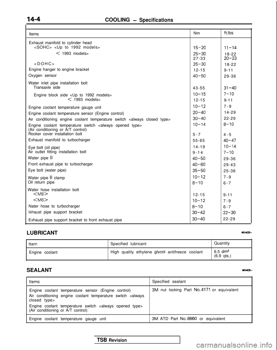
LUBRICANT Ml4CD-
Item
Engine coolant
Specified lubricant
High quality ethylene glycol
antifreeze coolant Quantity
6.5
dm3(6.9 qts.)
SEALANT
M14CE- Items
Specified sealant
Engine coolant temperature sensor (Engine control) 3M
nut locking Part No.4171
or equivalent
Air conditioning engine coolant temperature switch
closed type> Engine coolant temperature switch
(Air conditioning or A/T control)
Engine coolant temperature gauge unit 3M
ATD Part No.8660
or equivalent
TSB Revision
Page 557 of 1273

COOLING - Special TooVTroubleshooting
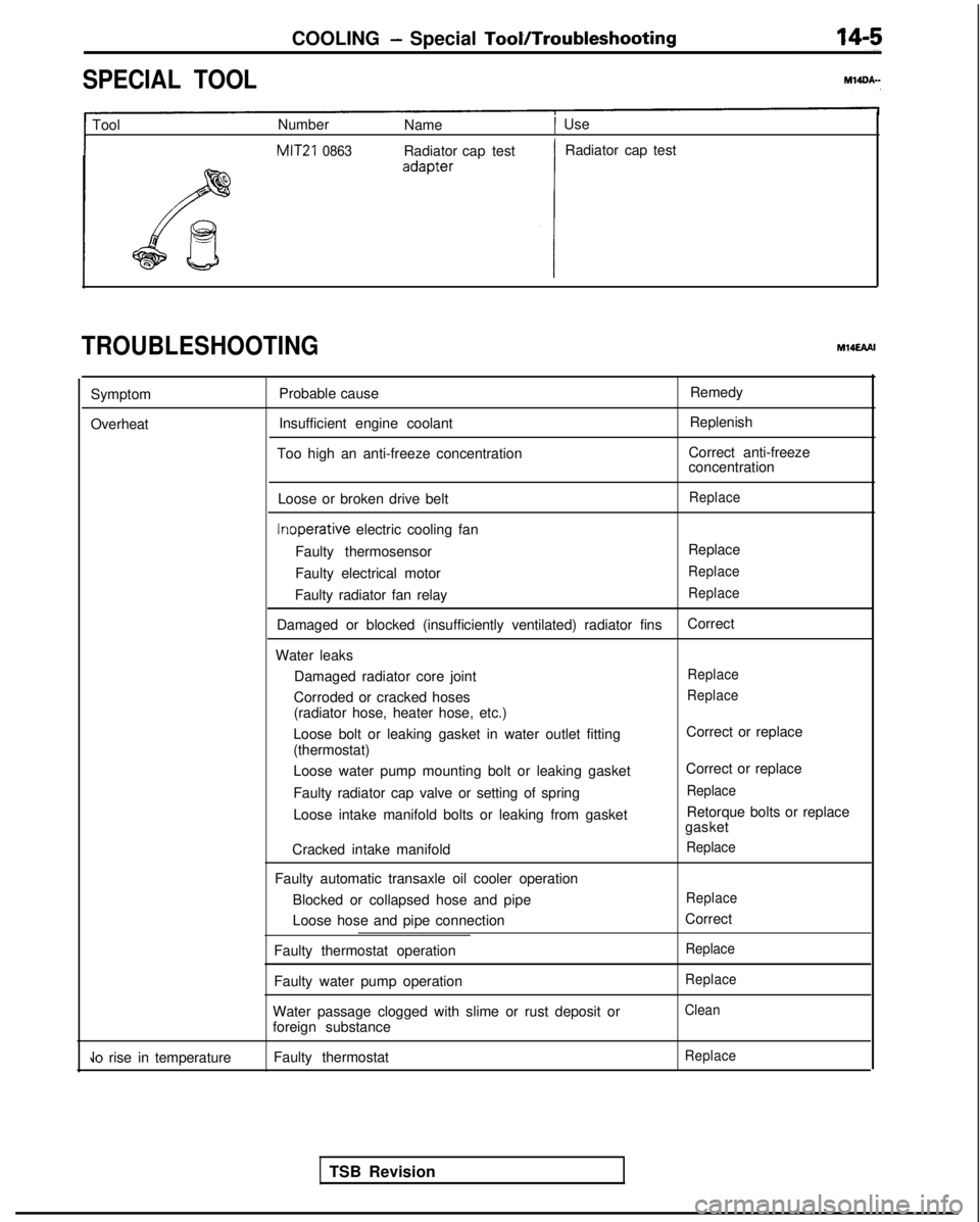
SPECIAL TOOL
1 Tool
Number
Name1 Use
MIT21 0863Radiator cap test Radiator cap test
TROUBLESHOOTINGM14EAAI
Symptom
Overheat Probable cause
Insufficient engine coolant
Too high an anti-freeze concentration Remedy
Replenish
Correct anti-freeze
concentration
Loose or broken drive belt
Replace Inoperative
electric cooling fan
Faulty thermosensor Replace
Faulty electrical motor
Replace
Faulty radiator fan relayReplace
Damaged or blocked (insufficiently ventilated) radiator fins Correct
Water leaks Damaged radiator core joint
Replace
Corroded or cracked hosesReplace
(radiator hose, heater hose, etc.)
Loose bolt or leaking gasket in water outlet fitting
(thermostat)
Loose water pump mounting bolt or leaking gasket
Faulty radiator cap valve or setting of spring
Loose intake manifold bolts or leaking from gasket
Cracked intake manifold
Faulty automatic transaxle oil cooler operation Blocked or collapsed hose and pipe
Loose hose and pipe connection
Faulty thermostat operation
Faulty water pump operation
Water passage clogged with slime or rust deposit or
foreign substance Correct or replace
Correct or replace
Replace
Retorque bolts or replace
gasket
Replace
Replace
Correct
Replace
Replace
Clean
Jo rise in temperature Faulty thermostatReplace
TSB Revision
Page 558 of 1273
14-6COOLING - Troubleshooting
CIRCUIT DIAGRAM
AWD-M/T)>
IGNJvJc
c
c
c
IONH(IG2)W&FUj$?LE
C-24
3
CONDENSER
FAN MOTOR
5r; 5(GY)(GY)
,,43AExAy4x3,“4 s
[“1“1 "2RADIATOR
RADIATORFAN MOTOR +FAN MOTOR1 RELAYCHI) gRELAYCLO)J5Ed
I ITHERM0 SENSOR
ON:85’C
(185’F)OFF38 C(172’Fl
A-29
*2-E
40---4
g 51
Pu
411
d
i
FAN MOTOR
2CONDENSER
FAN MOTOR
RELAY
(HI)
&WE;""
A-15
a3 ON:1800kPa
e56Ds I )
OFF:1500kPe
(233DSl)
KXBS-AC-HOEIf-NY
TSB Revision
Page 559 of 1273

COOLING -Troubleshootina14-7
L
ICSk-iNIq
ci
'ION:H(IG2)
W&FUS$BLE
AUTOCOMPRESSOR
CONTROL UNIT
A-29
'RADIATORFAN MOTOR43 RELAYCHI)cu
A-29
RESISTOR
> 'Mf AToR
m ON:SSC
OFF -p(165'F)
OFF:?8’C(172’F)$5m6‘5I%
66.
B-22-4 m
?
"A
OFF-ON:
102’
C0 KX35-AC-H0612-NY
I(GY) ;
2 "1"1
;-'SX!D%% BRELAY(L0) 0? -
N
d
0-
A-24
2
f
A-15
I
/OFFGE3
1
0N:lBOOkPa(256DS
II 0FF:lSOOkPs
2
(213PSl)
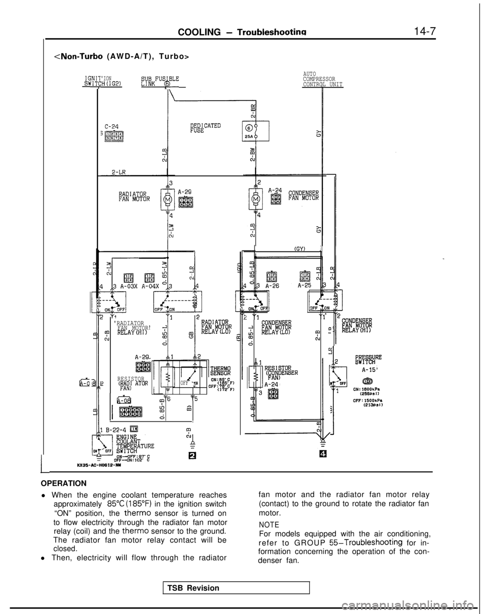
OPERATION l When the engine coolant temperature reaches approximately
85°C (185°F) in the ignition switch
“ON” position, the
therm0 sensor is turned on
to flow electricity through the radiator fan motor relay (coil) and the
therm0 sensor to the ground.
The radiator fan motor relay contact will be
closed.
l Then, electricity will flow through the radiator fan motor and the radiator fan motor relay
(contact) to the ground to rotate the radiator fan
motor.
NOTE
For models equipped with the air conditioning,
refer to GROUP
55-Troubleshooting for in-
formation concerning the operation of the con-
denser fan.
TSB Revision