Page 614 of 1273
15-28INTAKE AND EXHAUST - Exhaust Manifold
EXHAUST MANIFOLD
PEMOVAL AND INSTALLATION MlSNA-B
.15 Nm
1 ft.lbs.
7-l
40-50Nm ----‘--A
40-50 Nm /-29-36 ft.lbs.
30-40Nmj’22-29 ft.lbs.
Removal steps
1.Condenser fan motor (Vehicles with airconditioning)
2. Self locking nut
3. Gasket
4*4. Oxygen sensor5. Exhaust manifold cover (A)6. Self locking nut7. Engine hanger8. Exhaust manifold
9. Exhaust manifold gasket
IO. Exhaust manifold cover(B)
TSB Revision1
Page 615 of 1273
INTAKE AND EXHAUST - Exhaust Manifold 15-29
SERVICE POINTS OF REMOVAL
MlBNBAFl
4. REMOVAL OF OXYGEN SENSOR
Disconnect the connector of the oxygen sensor, and install
the special tool to the oxygen sensor.
Then, using an offset (box-end) wrench, remove the
oxygen sensor.
INSPECTION MlSNCALl
Check the following points; replace the part if a problem is
found.
EXHAUST MANIFOLD
Check for damage or cracking of any part.
EXHAUST MANIFOLD GASKET
Check for flaking or damage of the gasket.
Page 616 of 1273
15-30 INTAKE AND EXHAUST -Exhaust Manifold
EXHAUST MANIFOLD
REMOVAL AND INSTALLATION
I12-15 Nm9- 11ft.lbs.
27-33 Nm20-23 fklbs.
40 50 Nm29136 ft.lbs.yAS
40-50Nm29- 36ft.lbs.30-40Nm22- 29ft.lbs.12-15 1
30-40Nm9-11 ft.
\
UrnIbs.
MlINA-B
22-29 ft.lbs
Removal steps*b’.
1. Condenser fan motor (Vehicles with air conditioning except AWD A/T)
2. Self locking nut3. Gasket4. Exhaust manifold cover (A)
l *5. Oxygen sensor
6. Self locking nut
7. Engine hanger
8. Exhaust manifold
9. Exhaust manifold gasket
10. Exhaust manifold cover (B)
SERVICE POINTS OF REMOVALMl5NNAH
5. REMOVAL OF OXYGEN SENSOR
Disconnect the connector of the oxygen sensor, and install
the special tool to the oxygen sensor.
Then, using an offset (box-end) wrench, remove the oxygen
sensor.
INSPECTION
Refer to P.15-29i
TSB Revision M15NCA-l
Page 617 of 1273
INTAKE AND EXHAUST -Exhaust Manifold 15-31
EXHAUST MANIFOLD
REMOVAL AND INSTALLATION
12-15
Nm
Removal
12-15.Nm - g-11
ft.lbs.
steps
9-l 1 ftlbs.
lh ./-I
‘Uc Ml5NA.C
05AO192
Coolant
(Refer to GROUP
00-Maimtenance Service.)eDraining and Refilling Engine
1. Radiator (Referto GROUP 14-Radiator.)
2. Connection for air intake hose
3. Connection for vacuum hose
4. Connection for air hose A 5. Oxygen sensor connector
6. Air outlet fitting
7. Gasket
8. Heat protector A 9. Heat protector
B10. Self-locking nut
11. Engine hanger
12. Eye bolt
‘\!I 1
5
Ilation Operationl Draining and Refilling Engine
Oil
-
(Refer to GROUP 00-Main.tenance Service.)
13. Gasket14. Connection for water hose15. Connection for water pipe.B16. Self-locking nut17. Gasket18. Exhaust manifold
19. Exhaust manifold gasket
20. Ring
21. Gasket
TSB Revision1
Page 621 of 1273

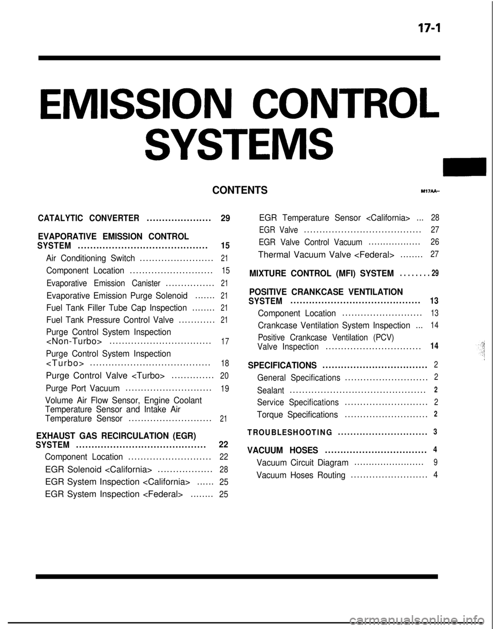
EMISSION CONTROL
SYSTEMS
CONTENTSr.w?API-
CATALYTIC CONVERTER.....................29
EVAPORATIVE EMISSION CONTROL
SYSTEM..........................................15
Air Conditioning Switch........................21
Component Location...........................15
Evaporative Emission Canister................21
Evaporative Emission Purge Solenoid.......21
Fuel Tank Filler Tube Cap Inspection........21
Fuel Tank Pressure Control Valve............21
Purge Control System Inspection
.................................17
Purge Control System Inspection
>
.......................................
18
Purge Control Valve
..............20
Purge Port Vacuum............................19
Volume Air Flow Sensor, Engine Coolant
Temperature Sensor and Intake Air
Temperature Sensor
...........................21
EXHAUST GAS RECIRCULATION (EGR)
SYSTEM..........................................22
Component Location...........................22
EGR Solenoid ..................28
EGR System Inspection
......25
EGR System Inspection ........25
EGR Temperature Sensor ...28
EGR Valve
......................................27
EGR Valve Control Vacuum..................26
Thermal Vacuum Valve ........27
MIXTURE CONTROL (MFI) SYSTEM. . . . . . . . 29
POSITIVE CRANKCASE VENTILATION
SYSTEM..........................................13
Component Location..........................13
Crankcase Ventilation System Inspection
...14
Positive Crankcase Ventilation (PCV)
Valve Inspection
...............................14
SPECIFICATIONS..................................2
General Specifications...........................2
Sealant............................................2
Service Specifications...........................2
Torque Specifications...........................2
TROUBLESHOOTING.............................3
VACUUM HOSES.................................4
Vacuum Circuit Diagram........................9
Vacuum Hoses Routing.........................4
Page 622 of 1273

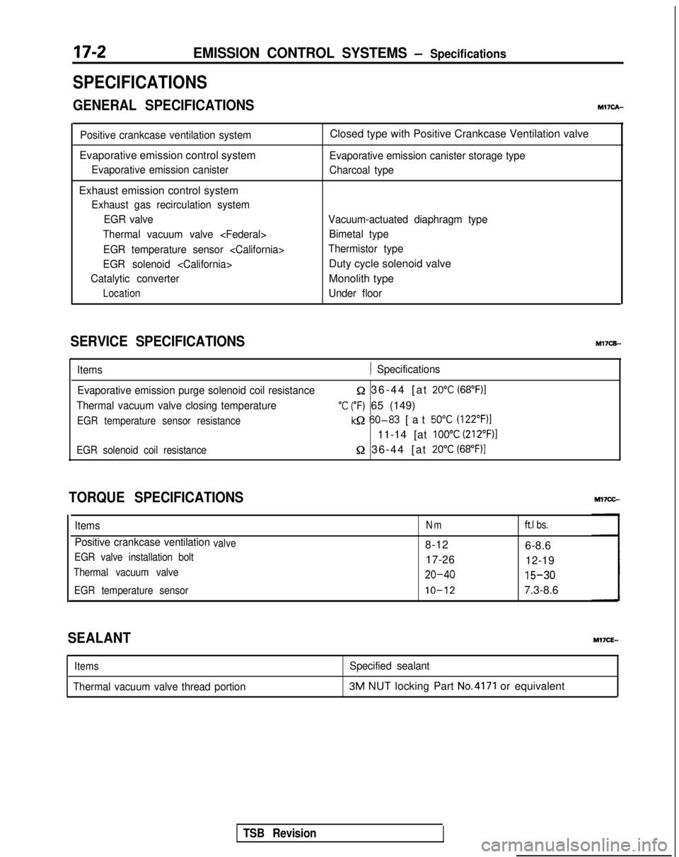
17-2EMISSION CONTROL SYSTEMS - Specifications
SPECIFICATIONS
GENERAL SPECIFICATIONSMl’IcA-
Positive crankcase ventilation system
Evaporative emission control system
Evaporative emission canister
Exhaust emission control system
Exhaust gas recirculation systemEGR valve
Thermal vacuum valve
EGR temperature sensor
EGR solenoid
Catalytic converter
Location
Closed type with Positive Crankcase Ventilation valve
Evaporative emission canister storage type
Charcoal type
Vacuum-actuated diaphragm type Bimetal type
Thermistor type
Duty cycle solenoid valve
Monolith type
Under floor
SERVICE SPECIFICATIONS M17CB-
Items1 Specifications
Evaporative emission purge solenoid coil resistance
Thermal vacuum valve closing temperature
EGR temperature sensor resistance
Q 36-44 [at 20°C (68”F)I
‘C (“F) 65 (149)
kQ 60-83
[at 50°C (122”F)l
11-14 [at 100°C (212”F)l
EGR solenoid coil resistance52 36-44 [at 20°C (68°F))
TORQUE SPECIFICATIONS
ItemsNmft.1 bs.
Positive crankcase ventilationvalve8-12
6-8.6
EGR valve installation bolt17-2612-19
Thermal vacuum valve20-40 15-30
EGR temperature sensorIO-127.3-8.6
SEALANT
Items
Thermal vacuum valve thread portion
Specified sealant3M NUT locking Part No.4171 or equivalent
TSB Revision
Page 638 of 1273
EMISSION CONTROL SYSTEMS -Evaporative Emission Control System
PURGE CONTROL SYSTEM INSPECTION M17lBBL
Evaporative
emission canister
Intake air temperature sensorEngine coolant temperature sensor re
Engine control module
I(1)Disconnect the purge air hose from the air intake hose, and
plug the air intake hose. Then, connect the hand vacuum
pump to the purge air hose.
(2) Under the engine conditions shown below, check by
applying vacuum from a hand vacuum pump.
When engine is cold-coolant temperature:
60°C (140°F) or less
Engine operating Applying vacuumResultcondition
1 vacuum is maintained 1ldldl rpm1 gy?r$y)
[ TSB Revision
Page 641 of 1273

EMISSION CONTROL SYSTEMS -Evaporative Emission Control System17-21EC1510
6EM137
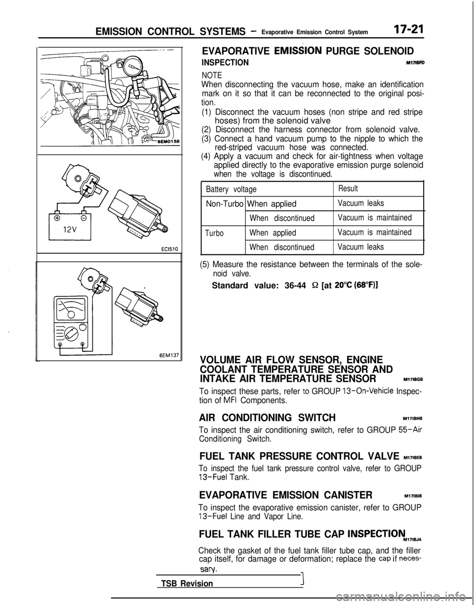
EVAPORATIVE EMlS$lON
PURGE SOLENOID
INSPECTIONM17lBFD
NOTE
When disconnecting the vacuum hose, make an identification
mark on it so that it can be reconnected to the original posi-
tion.
(1) Disconnect the vacuum hoses (non stripe and red stripe
hoses) from the solenoid valve
(2) Disconnect the harness connector from solenoid valve.
(3) Connect a hand vacuum pump to the nipple to which the red-striped vacuum hose was connected.
(4) Apply a vacuum and check for air-tightness when voltage applied directly to the evaporative emission purge solenoid
when the voltage is discontinued.
Battery voltageResult
Non-Turbo When appliedVacuum leaks
When discontinued Vacuum is maintained
TurboWhen appliedVacuum is maintained
When discontinued Vacuum leaks
(5) Measure the resistance between the terminals of the sole-
noid valve.
Standard value: 36-44 Q [at 20°C (68”F)l
VOLUME AIR FLOW SENSOR, ENGINE
COOLANT TEMPERATURE SENSOR AND
INTAKE AIR TEMPERATURE SENSOR
M17IBGB
To inspect these parts, refer to GROUP 13-On-Vehicle Inspec-
tion of
MFI Components.
AIR CONDITIONING SWITCH Ml7IBHB
To inspect the air conditioning switch, refer to GROUP
55-Air
Conditioning Switch.
FUEL TANK PRESSURE CONTROL VALVE MI’IIBEB
To inspect the fuel tank pressure control valve, refer to GROUP
13-Fuel
Tank.
EVAPORATIVE EMISSION CANISTERM17lBlB
To inspect the evaporative emission canister, refer to GROUP
13-Fuel Line and Vapor Line.
FUEL TANK FILLER TUBE CAP INSPECTIONM,7,w~
Check the gasket of the fuel tank filler tube cap, and the filler
cap itself, for damage or deformation; replace the
cap if neces-
sary.
TSB RevisionI