Page 807 of 1273

AUTOMATIC TRANSAXLE - Transaxle Assembly
TRANSAXLE ASSEMBLY
REMOVAL AND INSTALLATION
23-101
mz3u-
Pre-removal and Post-installation Op-eration@Draining and Supplying of the TransaxleFluid(Refer to GROUP 00-Maintenance Ser-vice.)*Removal and Installation of the Batteryand Battery TrayofRemoval and Installation of the Air Clean-
fRrefer to GROUP 15-Air
Cleaner.)*Removal and Installation of the Air Com-pressor(Vehicles with ACTIVE-ECS)(Refer to GROUP 33B-Air Compressor.)
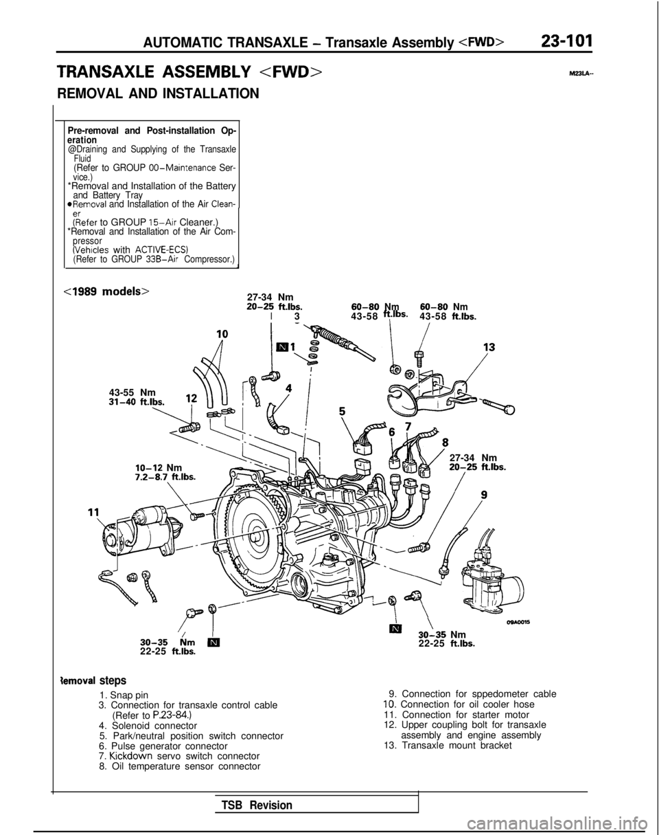
cl989 models>27-34 Nm20-25ft.lbs.I360-80Nm43-58ft.lbS.60-80Nm43-58ft.lbs.
43-55 Nm
IO-12 Nm7.2-8.7 ft.lbs.
27-34 Nm20-25 ft.lbs.
30-35 km
b22-25 ft.lbs.
Iii ’30-35 Nm
22-25 ft.lbs.
ternoval steps
1. Snap pin
3. Connection for transaxle control cable
(Refer to
P.23-84.)4. Solenoid connector5. Park/neutral position switch connector
6. Pulse generator connector
7. Kickdown
servo switch connector
8. Oil temperature sensor connector 9. Connection for sppedometer cable
10. Connection for oil cooler hose
11. Connection for starter motor
12. Upper coupling bolt for transaxle assembly and engine assembly
13. Transaxle mount bracket
TSB Revision
Page 808 of 1273
23-102AUTOMATIC TRANSAXLE - Transaxle Assemblv
27-34 Nm220-25 ftlbs.
\
43-55 Nm
60-80 Nm
60-80 Nm
/43-58 ftlbs.
43-58
ftlbs.
/\ /\ 930-35 NmDm 30-35 N
m
22-25
ftlbs.22-25 ft.lbs.
Iemoval steps
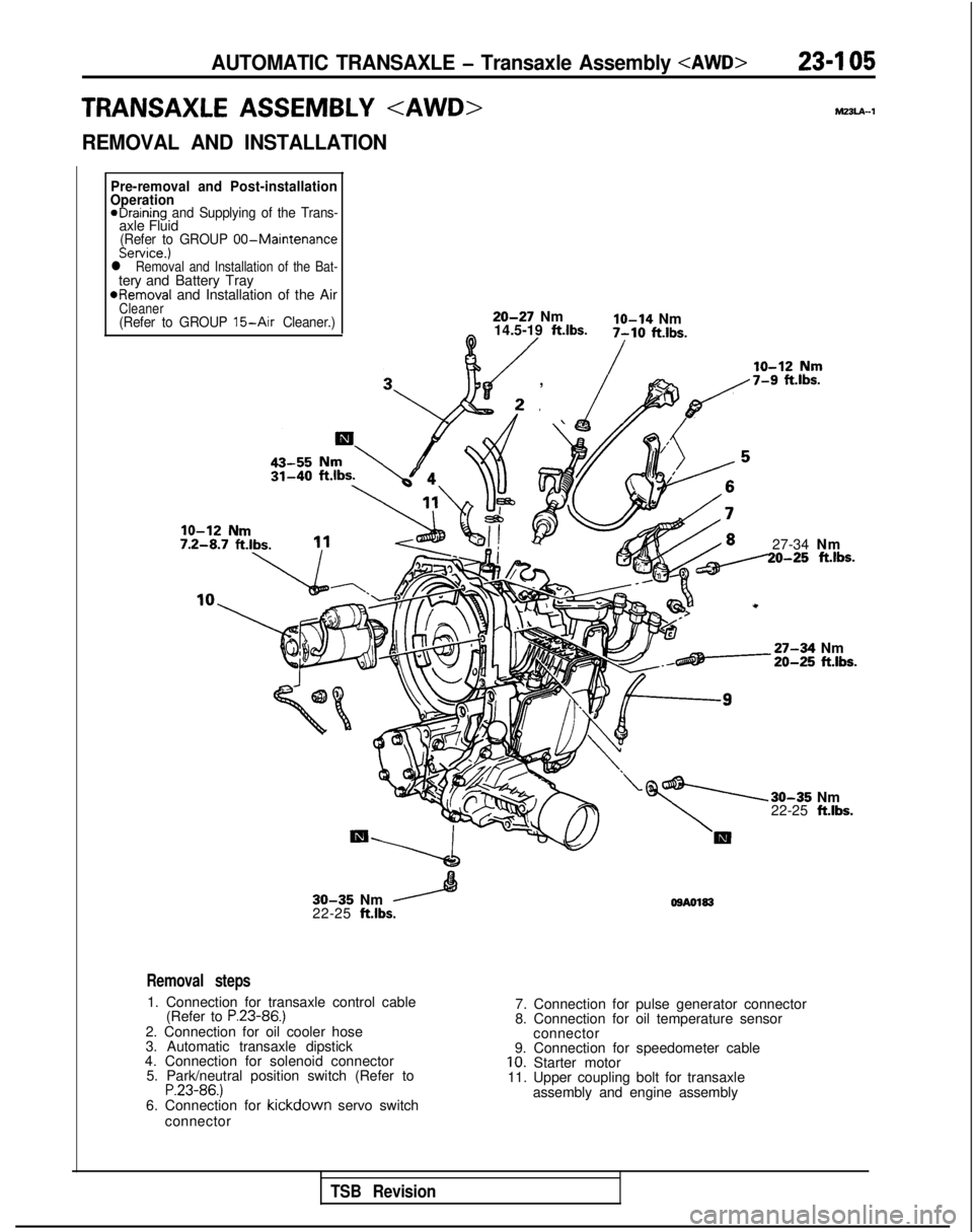
2. Adjusting nut
3. Connection for transaxle control cable (Refer to
P.23-85.)4. Solenoid connector
5. Park/neutral position switch connector
6. Pulse generator connector
7. Kickdown
servo switch connector
8. Oil temperature sensor connector
9. Connection for speedometer cable
10. Connection for oil cooler hose
11. Connection for starter motor
12. Upper coupling bolt for transaxle assembly and engine assembly
13. Transaxle mount bracket
TSB Revision
Page 811 of 1273

AUTOMATIC TRANSAXLE - Transaxle Assembly 23-I 05
TRANSAXLE ASSEMBLY hl33lA-1
REMOVAL AND INSTALLATION
Pre-removal and Post-installation
Operation
eDraining and Supplying of the Trans-axle Fluid(Refer to GROUP 00-MaintenanceService.)l Removal and Installation of the Bat-tery and Battery Tray
*Removal
and Installation of the Air
Cleaner(Refer to GROUP 15-Air Cleaner.)20-27 Nmlo-14 Nm
14.5-19 ft.lbs.0 /7-10 ft.lbs.
/
, \ fp,/7-9 f%.lbs.
27-34 Nm20-25 ft.lbs.
-27-34 Nm20-25 ft.lbs.
30-35 Nm
22-25 ft.lbs.
30-35 Nm
22-25 ft.lbs. OSA0183
Removal steps
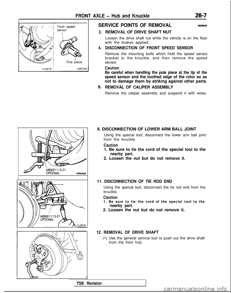
1. Connection for transaxle control cable
(Refer to P.23-86.)2. Connection for oil cooler hose
3. Automatic transaxle dipstick
4. Connection for solenoid connector 5. Park/neutral position switch (Refer to
P.23-86.)6. Connection for kickdown servo switch
connector 7. Connection for pulse generator connector
8. Connection for oil temperature sensor
connector
9. Connection for speedometer cable
10. Starter motor
11. Upper coupling bolt for transaxle
assembly and engine assembly
TSB Revision
Page 832 of 1273
Page 836 of 1273
26-6FRONT AXLE -Hub and Knuckle
HUB AND
KNUCKLE
REMOVAL AND INSTALLATION
SO-105 Nm
65-76 ft.lbs.
Vehicles with ACTIVE-ECS*’
80-100 Nm’\58-72 ftlbs.
9-14 Nm7- 10 ft.lbs.I
I
5rq :I
u
- 4. .i,'-
B860-72 Nm200-‘260 Nm
43-52
ft.lbs.IU-188 ft.lbs.
llA0121
Removal steps
l +1. Cotter pin
+e I)+ 2. Drive shaft nut
l + 3. Washer
a*4. Front speed sensor connection< Vehicules
with A.B.S.*‘> (Refer toGROUP 35-Speed sensor)a*5. Caliper assembly
6. Brake disc
7. Front height sensor connection
(Refer to GROUP 33B-Height sensor)
8. Self locking nut
+e ~~9. Lower arm ball joint connection
10. Cotter pin
::11. Tie rod end connection
12. Drive shaft
13. Front strut mounting bolt
14. Hub and knuckle
NOTE
::: Anti-lock braking system: ACTIVE-Electronic Control Suspension
TSB Revision
Page 837 of 1273

FRONT AXLE - Hub and Knuckle26-7
SERVICE POINTS OF REMOVALM261sAE
2.
4.
REMOVAL OF DRIVE SHAFT NUTLoosen the drive shaft nut while the vehicle is on the floor
with the brakes applied.
DISCONNECTION OF FRONT SPEED SENSOR
Remove the mounting bolts which hold the speed sensor
bracket to the knuckle, and then remove the speed
sensor.
Caution
Be careful when handling the pole piece at the tip of the
speed sensor and the toothed edge of the rotor so as
not to damage them by striking against other parts.
REMOVAL OF CALIPER ASSEMBLY
Remove the caliper assembly and suspend it with wires.
9. DISCONNECTION OF LOWER ARM BALL JOINT Using the special tool, disconnect the lower arm ball joint
from the knuckle.
Caution
1. Be sure to tie the cord of the special tool to the
nearby part.
2. Loosen the nut but do not remove it.
11. DISCONNECTION OF TIE ROD END
Using the special tool, disconnect the tie rod end from the
knuckle.
Caution
1. Be sure to tie the cord of the special tool to the
nearby part.
2. Loosen the nut but do not remove it.
12. REMOVAL OF DRIVE SHAFT
(1) Use the general service tool to push out the drive shaft from the front hub.
l\\11RO101 1
TSB Revision
Page 839 of 1273
FRONT AXLE - Hub and Knuckle26-9
DISASSEMBLY AND REASSEMBLY
9-14 Nm7-10 ft.lbs.i !81
Disassembly steps
::
I. Front hub
2. Oil seal (drive shaft side)
3.Snapring
4. Oil seal (hub side)
4*5. Wheel bearing6.Dust shield
7. Knuckl
e
8. Front toothed rotor
(Refer to GROUP
35-Wheel Speed
Sensor.)
WA0374
Reassembly steps
8. Front toothed rotor
(Refer to GROUP 35-Wheel SpeedSensor.)7. Knuckle.
6. Dust shield
I)+ 5. Wheel bearingl +4. Oil seal (hub side) 3. Snap ring
I)+ 1. Front hubI)*Adiustment of wheel bearing starting torque
I)+2. Oil seal (drive shaft side)
SERVICE POINTS OF DISASSEMBLY
Mz6lFAM
1. REMOVAL OF FRONT HUB (1) Attach the special tools to the knuckle and front hub.
(2) Secure the knuckle in a vise.
(3) Tighten the nut of the special tool and remove the front hub from the knuckle.
Caution
1. Be sure to use the special tools.
2.If the front hub and knuckle are disassembled by
striking them with a hammer, the bearing will
be damaged.
TSB RevisionI
Page 843 of 1273

FRONT AXLE - Drive Shaft2643
REMOVAL AND INSTALLATION
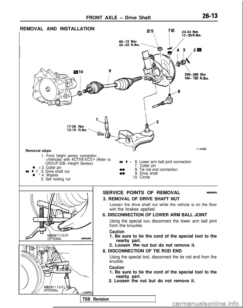
7m
24-34 Nm 17-25ft.Ibs.
144- 188ft.lbs.
6
17-26 Nm12-19 ft.lbs.
Removal steps11 A0099
1. Front height sensor connection
(Refer toGROUP33B-Height Sensor)
l + 2. Cotter pin+e l C3. Drive shaft nutl * 4. Washer
5. Self locking nut
4I) l +6. Lower arm ball joint connection7.Cotterpin
4+8. Tie rod end connection
4*9. Drive shaft10.Circlip
12R0258
SERVICE POINTS OF REMOVALM280BAL
3. REMOVAL OF DRIVE SHAFT NUT
Loosen the drive shaft nut while the vehicle is on the floor
with the brakes applied.
6. DISCONNECTION OF LOWER ARM BALL JOINT
Using the special tool, disconnect the lower arm ball joint
from the knuckle.
Caution
1. Be sure to tie the cord of the special tool to the
nearby part.
2. Loosen ~the nut but do not remove it.
8. DISCONNECTION OF TIE ROD END
Using the special tool, disconnect the tie rod end from the
knuckle.
Caution
1. Be sure to tie the cord of the special tool to the
nearby part.
2. Loosen the nut but do not remove it.
TSB Revision