Page 862 of 1273
27-2REAR AXLE - Specifications/Troubleshooting
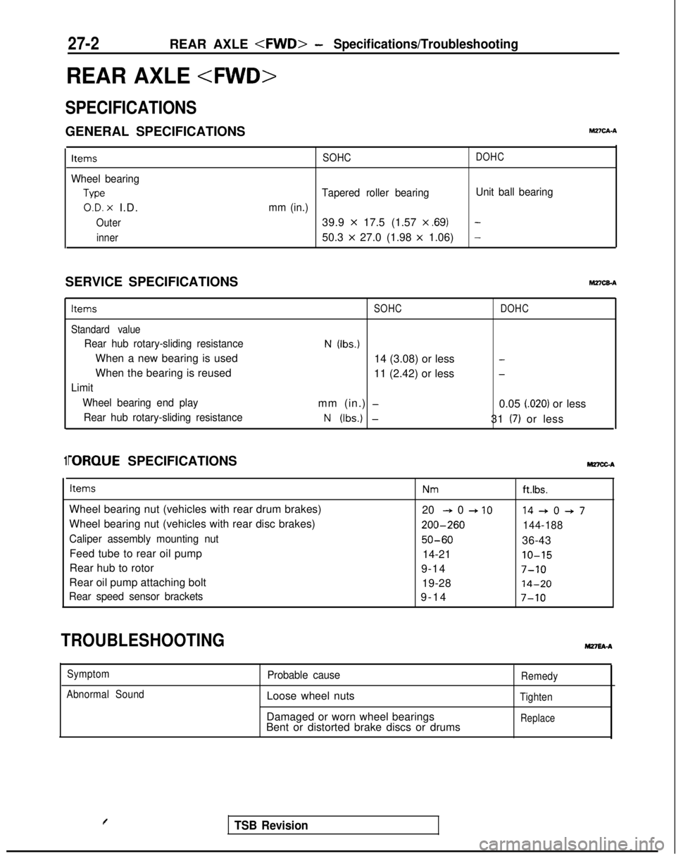
REAR AXLE
SPECIFICATIONS
GENERAL SPECIFICATIONSM2?CA-A
Items
Wheel bearing
Type
O.D. x I.D.
Outer
inner SOHC
DOHC
Tapered roller bearing
Unit ball bearing
mm (in.)
39.9 x 17.5 (1.57 x ,691-
50.3 x 27.0 (1.98 x 1.06)-
SERVICE SPECIFICATIONShl27CEA
Items
Standard value
Rear hub rotary-sliding resistance
When a new bearing is used
When the bearing is reused
Limit Wheel bearing end playRear hub rotary-sliding resistance
SOHC
N (Ibs.)
14 (3.08) or less
11 (2.42) or less
mm (in.)
-
N (Ibs.) -
DOHC
-
-
0.05 i.020) or less
31
(7) or less
1i-ORQUE SPECIFICATIONS MnCGA
Items
Wheel bearing nut (vehicles with rear drum brakes)
Wheel bearing nut (vehicles with rear disc brakes)
Caliper assembly mounting nut
Feed tube to rear oil pump
Rear hub to rotor
Rear oil pump attaching bolt
Rear speed sensor brackets
Nmft.lbs.
20 + 0 + IO14+0+7 200-260
144-188
50-6036-43
14-21
IO-15
9-147-10
19-2814-20
9-1
4
7-10
TROUBLESHOOTINGM27EA-A
Symptom
Abnormal SoundProbable cause
Loose wheel nuts
Damaged or worn wheel bearings
Bent or distorted brake discs or drums
Remedy
Tighten
Replace
TSB Revision
Page 868 of 1273
27-8REAR AXLE -4WD>- Rear Axle Hub
REAR AXLE HUB
REMOVAL AND INSTALLATION
M27MA-A
9-14 Nm7-10 ft.lbs.
50-60 Nm
36-43 ftlbs.
Removal steps
+*1. Rear speed sensor 4*2. Caliper assembly
3. Brake disc
I!jiEl 4
llA0030
4. Hub capl 45.
Nut6.Tonguedwasher
7. Rear hub assembly+*8. Rear rotor 9. Rear hub bearing unit
Rear speedsensor14ROlMI
SERVICE POINTS OF REMOVAL
1. REMOVAL OF REAR SPEED SENSOR
Caution
M27wBAB
When removing the speed sensor from the adapter, be
careful that the end pole piece does not strike the teeth
of the rotor or other parts.
TSB Revision
Page 871 of 1273
REAR AXLE - SDecifications27-11
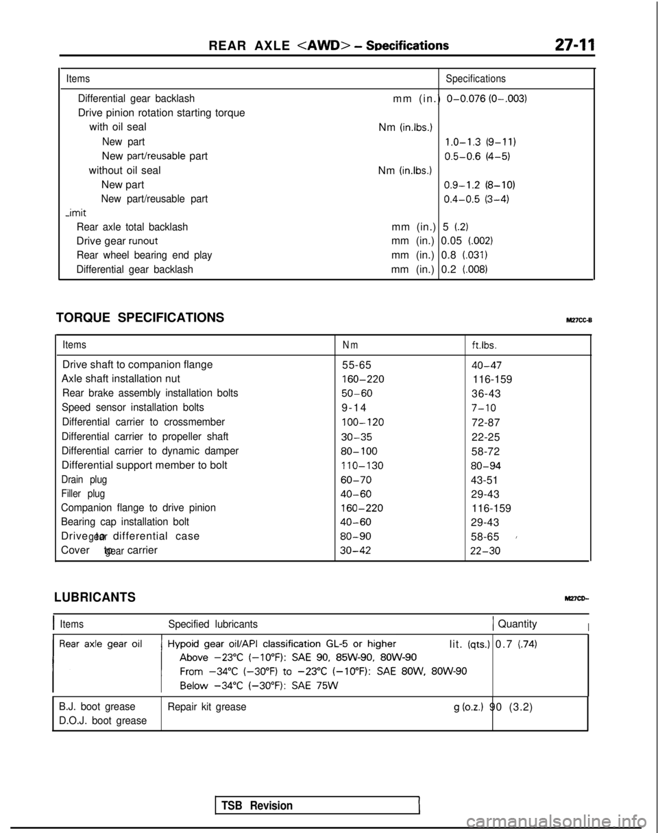
Items
Differential gear backlash
Drive pinion rotation starting torque
with oil seal
New part
New part/reusable part
without oil seal New part
New part/reusable part -imit
Rear axle total backlash
Drive gear runout
Rear wheel bearing end play
Differential gear backlash
Specifications
mm (in.) O-0.076 (O-.003)
Nm (in.lbs.) 1.0-1.3
(9-11)
0.5-0.6
(4-5)
Nm
(in.lbs.1 0.9-1.2
(8-10)
0.4-0.5
(3-4)
mm (in.) 5
(2)
mm (in.) 0.05 (.002)
mm (in.) 0.8 (.031)
mm (in.) 0.2 (008)
TORQUE SPECIFICATIONSM27cc-B
ItemsNmft.lbs.
Drive shaft to companion flange 55-6540-47
Axle shaft installation nut 160-220
116-159
Rear brake assembly installation bolts50-6036-43
Speed sensor installation bolts9-1
4
7-10
Differential carrier to crossmember
100-120
72-87
Differential carrier to propeller shaft30-3522-25
Differential carrier to dynamic damper80- 10058-72
Differential support member to bolt 110-130
80-94
Drain plug60-7043-51
Filler plug40-6029-43
Companion flange to drive pinion
160-220
116-159
Bearing cap installation bolt40-6029-43
Drive to differential case
gear80-9058-651
Cover to carriergear30-4222-30
TSB Revision
LUBRICANTS
IItemsSpecified lubricants1 QuantityI
lit. (qts.) 0.7 (74)
B.J. boot grease Repair kit grease
g (oz.) 90 (3.2)
D.O.J. boot grease
Page 877 of 1273
REAR AXLE - Axle Shaft27-17
AXLE SHAFT
IEMOVAL
AND INSTALLATION
55-65
Nm 40-47
ftlbs.160-220NmI116-159
Ift.lbs.36-43 50-60ft.lbs. Nm
Post-installation OperationKonnecting of Parking Brake Cable End@Adjusting Parking Brake LeverStroke (Refer to GROUP 36-Service
Adjustment Procedures.)
9-14 Nmq------7-10 ft.lbs.
llA0041
Removal steps
4*1. ifsa.yyed sensor
4*2. Brake caliper assembly3.Brake disc4. Drive shaft mounting nut+I) e+ 5. Self locking nut6.Washer7.Companion flange4*8. Axle shaft assembly+e l +9. Rear rotor l e l + 10.Outer bearing+e ++ 11. Dust cover~~ 12. Dust cover13.Axle shaft4*l 414.Oil seal+e l + 15. inner bearing Trailing
arm 15
SERVICE POINTS OF REMOVAL
MmwAN
1.REMOVAL OF REAR SPEED SENSOR
A.B.S.>
NOTE
Be cautious to ensure that the tip of the pole piece does
not come in contact with other parts
when removing the
speed sensor.
2. REMOVAL OF BRAKE CALIPER ASSEMBLY
Remove the brake caliper assembly and suspend it with a
piece of wire.
I- _,1 TSB RevisionI
Page 940 of 1273
339-l
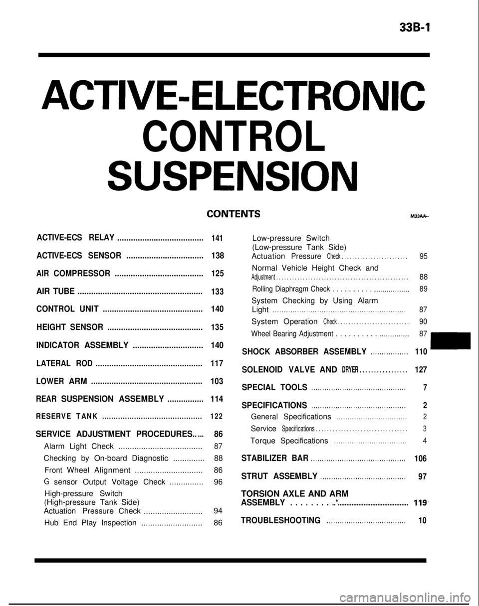
ACTIVE-ELECTRONIC
CONTROL
SUSPENSION
ACTIVE-ECS RELAY......................................141
ACTIVE-ECSSENSOR.................................. 138
AIRCOMPRESSOR.......................................125
AIR TUBE.......................................................133
CONTROLUNIT............................................ 140
HEIGHT SENSOR ..........................................
135
INDICATORASSEMBLY............................... 140
LATERALROD...............................................117
LOWER
ARM.................................................103
REAR
SUSPENSION ASSEMBLY................114
RESERVETANK............................................ 122
SERVICE ADJUSTMENT PROCEDURES.....86
Alarm Light Check.....................................87
Checking by On-board Diagnostic ..............88
FrontWheelAlignment .............................. 86
G sensor Output Voltage Check ...............96
High-pressure Switch
(High-pressure Tank Side)
Actuation Pressure Check
.......................... 94
Hub End Play Inspection ...........................86 M33AA-
Low-pressure Switch
(Low-pressure Tank Side)
Actuation
PressureCheck . . . . . . . . . . . . . . . . . . . . . . . . .95
Normal Vehicle Height Check and
Adjustment . . . . . . . . . . . . . . . . . . . . . . . . . . . . . . .\
. . . . . . . . . . . . . . . . . . .88
Rolling Diaphragm Check . . . . . . . . . . .._.............. 89
System Checking by Using Alarm
Light
. . . . . . . . . . . . . . . . . . . . . . . . . . . . . . . . . . . . \
. . . . . . . . . . . . . . . . . . . . . . . .87
System OperationCheck . . . . . . . . . . . . . . . . . . . . . . . . . . .90
Wheel Bearing Adjustment . . . . . . . . . .
.._........... 87
SHOCKABSORBER ASSEMBLY. . . . . . . . . . . . . . . . .110
SOLENOIDVALVEANDDRYER . . . . . . . . . . . . . . . . .127
SPECIAL TOOLS. . . . . . . . . . . . . . . . . . . . . . . . . . . . . . . . . . . . \
. . . . . . .7
SPECIFICATIONS. . . . . . . . . . . . . . . . . . . . . . . . . . . . . . . . . . . . \
. . . . . . .2
GeneralSpecifications. . . . . . . . . . . . . . . . . . . . . . . . . . . . . . . .2
ServiceSpecifications . . . . . . . . . . . . . . . . . . . . . . . . . . . . .\
. . . .3
TorqueSpecifications. . . . . . . . . . . . . . . . . . . . . . . . . . . . . . . . .4
STABILIZER BAR. . . . . . . . . . . . . . . . . . . . . . . . . . . . . . . . . . . . \
. . . . . . .106
STRUT ASSEMBLY. . . . . . . . . . . . . . . . . . . . . . . . . . . . . . . . . . . . \
. . .97
TORSION AXLE AND ARM
ASSEMBLY. . . . . . . . ..*.........................................119,
TROUBLESHOOTING. . . . . . . . . . . . . . . . . . . . . . . . . . . . . . . . . . . .10
Page 942 of 1273
ACTIVE-ELECTRONIC CONTROL SUSPENSION - Specifications33B-3
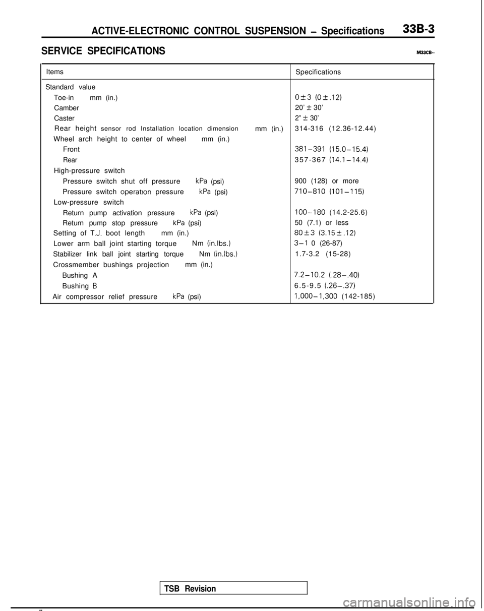
SERVICE SPECIFICATIONSM33cE-
ItemsSpecifications
Standard value Toe-in mm (in.)
O&3 (O-t.12)
Camber 20’ t 30’
Caster
2” t 30’
Rear height sensor rod Installation location dimension
mm (in.)314-316 (12.36-12.44)
Wheel arch height to center of wheel mm (in.)
Front
381-391 (15.0-15.4)
Rear357-367 (14.1-14.4)
High-pressure switch
Pressure switch shut off pressure
kPa (psi) 900 (128) or more
Pressure switch operatton
pressure
kPa (psi)710-810 (101-115)
Low-pressure switch
Return pump activation pressure
kPa (psi)100-180 (14.2-25.6)
Return pump stop pressure
kPa (psi) 50 (7.1) or less
Setting of
T.J. boot length mm (in.)80+3 (3.152.12)
Lower arm ball joint starting torque Nm (inlbs.)3-l 0 (26-87)
Stabilizer link ball joint starting torque Nm (in.lbs.)
1.7-3.2 (15-28)
Crossmember bushings projection mm (in.)
Bushing A
7.2-10.2 (.28-.40)
Bushing B6.5-9.5 (.26-.37)
Air compressor relief pressurekPa (psi) l,OOO-1,300
(142-185)
TSB Revision
Page 943 of 1273
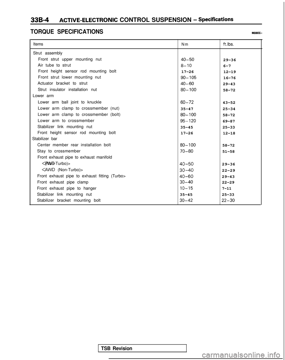
33B-4ACTIVE-ELECTRONIC CONTROL SUSPENSION - Specifications
TORQUE SPECIFICATIONS
Items
Strut assembly Front strut upper mounting nut
Air tube to strut Front height sensor rod mounting bolt
Front strut lower mounting nut
Actuator bracket to strut
Strut insulator installation nut
Lower arm
Lower arm ball joint to knuckle
Lower arm clamp to crossmember (nut)
Lower arm clamp to crossmember (bolt)
Lower arm to crossmember
Stabilizer link mounting nut
Front height sensor rod mounting bolt
Stabilizer bar
Center member rear installation bolt
Stay to crossmember Front exhaust pipe to exhaust manifold
(Non-Turbo)>
Front exhaust pipe to exhaust fitting (Turbo>
Front exhaust pipe clamp
Front exhaust pipe to hanger
Stabilizer link mounting nut
Stabilizer bracket mounting boltNmftlbs.
40-5029-36
8-106-7
17-26 12-19 go-105
16-76
40-6029-43 80-100
58-72 60-72
43-52
35-47 25-34 80-100
58-72 95-120
69-87
35-45 25-33
17-26 12-18 80-100
58-72 70-80
51-58
40-5029-36
30-4022-29
40-6029-43 30-40
22-29 IO-15
7-11
35-45
25-33 30-42 22-30
TSB Revision
Page 944 of 1273
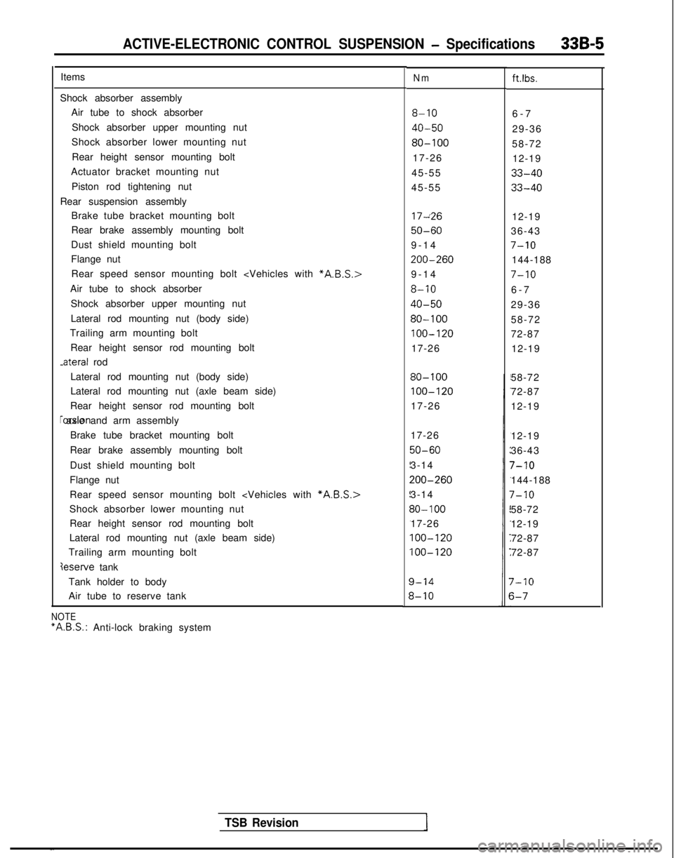
ACTIVE-ELECTRONIC CONTROL SUSPENSION - Specifications33B-5
ItemsNmft.lbs.
Shock absorber assemblyAir tube to shock absorber
Shock absorber upper mounting nut
Shock absorber lower mounting nut
Rear height sensor mounting bolt
Actuator bracket mounting nut
Piston rod tightening nut
Rear suspension assembly Brake tube bracket mounting bolt
Rear brake assembly mounting bolt
Dust shield mounting bolt
Flange nut
8-106-
7
40-5029-36
80-10058-72
17-26 12-19
45-55
33-40
45-5533-40
Rear speed sensor mounting bolt
Air tube to shock absorber
Shock absorber upper mounting nut
Lateral rod mounting nut (body side)
Trailing arm mounting bolt
Rear height sensor rod mounting bolt -ateral
rod 17~26
12-19
50-6036-43
9-1
4
7-10
200-260144-188
9-1
4
7-10
8-106-
7
40-5029-36
80-10058-72
100-12072-87
17-26 12-19
Lateral rod mounting nut (body side)
Lateral rod mounting nut (axle beam side)
Rear height sensor rod mounting bolt rorsion axle and arm assembly
Brake tube bracket mounting bolt
Rear brake assembly mounting bolt
Dust shield mounting bolt
Flange nut
80-100
100-120
17-26 58-72
72-87
12-19
Rear speed sensor mounting bolt
*A.B.S.>
Shock absorber lower mounting nut Rear height sensor rod mounting bolt
Lateral rod mounting nut (axle beam side)
Trailing arm mounting bolt
deserve tank 17-26
50-60
3-14
200-260
3-14
30- 100
17-26
100-120
100-120
12-19
36-43
7-10
144-188
7-10
58-72
12-19
72-87
72-87
Tank holder to body
Air tube to reserve tank
7-10
s-7
TSB Revision
NOTE “A.B.S.:
Anti-lock braking system