Page 642 of 1273
17-22EMISSION CONTROL SYSTEMS -Exhaust Gas Recirculation (EGR) System
EXHAUST GAS RECIRCULATION (EGR) SYSTEM
COMPONENT LOCATION
Name
EGR solenoid
EGR valve
EGR temperature sensor
Thermal vacuum valve
Symbol
D
B
C
A
\ temperature
-, ‘F-$
3
i
bEM0148
1 TSB Revision
Page 643 of 1273
EMISSION CONTROL SYSTEMS -Exhaust Gas Recirculation (EGR) System17-23
INameISymbol 1
IEGR solenoid I D I
EGR valve
EGR temperature sensor
B
C
1 Thermal vacuum valve 1 A 1
\
. ,6FUl93~
I
TSB Revision\i
Page 644 of 1273
17-24EMISSION CONTROL SYSTEMS- Exhaust Gas Recirculation (EGR) System
Name
EGR solenoid
EGR valve
EGR temperature sensor
Thermal vacuum valve
Symbol
D
B
C
A
6EM0166
TSB Revision
Page 648 of 1273

17-28EMISSION CONTROL SYSTEMS -Exhaust Gas Recirculation (EGR) Svstem
n
7@
REMOVAL
(1) When removing the thermal vacuum valve, do not use
wrenches or other tools on the resin part.
(2) When disconnecting the vacuum hose, put a mark on thehose so that it may be reconnected at original position.
INSTALLATION
(1) Apply specified sealant to the threads of thermal vacuumvalve and tighten to specified torque. When installing the
thermal vacuum valve, do not use wrenches or other tools
on the resin part.
Specified sealant: 3M
NUT Locking Part
No.4171 or equivalent
Specified torque:
20-40 Nm (15-30 ft.lbs.)
(2) Reconnect the vacuum hose as it was before.
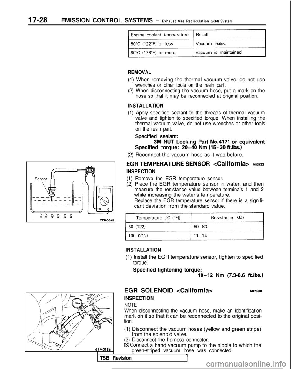
EGR TEMPERATURE SENSOR Ml’IICZB
INSPECTION
(1) Remove the EGR temperature sensor.
(2) Place the EGR temperature sensor in water, and then
measure the resistance value between terminals 1 and 2
while increasing the water’s temperature.
Replace the EGR temperature sensor if there is a signifi-
cant deviation from the standard value.
INSTALLATION
(1) Install the EGR temperature sensor, tighten to specified
torque.
Specified tightening torque:
lo-12 Nm (7.3-8.6 ft.lbs.1
EGR SOLENOID
INSPECTION
NOTE
Ml7ICRB
When disconnecting the vacuum hose, make an identification
mark on it so that it can be reconnected to the original posi-
tion.
(1) Disconnect the vacuum hoses (yellow and green stripe)
from the solenoid valve.
(2) Disconnect the harness connector.
(3) Connect a hand vacuum pump to the nipple to which the
green-striped vacuum hose was connected.
TSB Revision
Page 666 of 1273

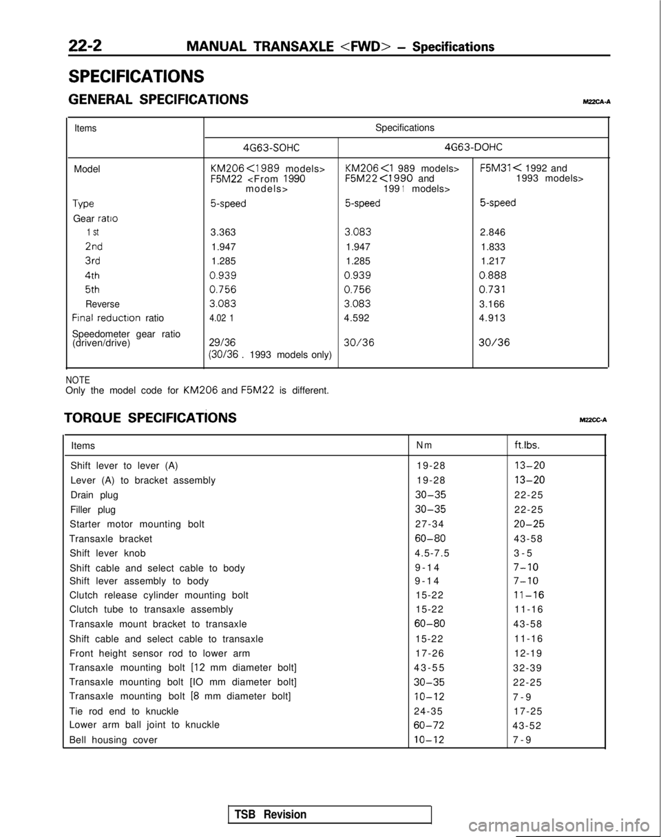
22-2MANUAL TRANSAXLE
- Specifications
SPECIFICATIONS
GENERAL SPECIFICATIONSMZXA-A
ItemsSpecifications 4G63-SOHC 4G63-DOHC
Model KM206
<1989 models> KM206
F5M31 < 1992 and F5M22
<1990 and 1993 models>
models> 1991models>
Type5-speed5-speed 5-speed
Gear ratio
1 St3.363
3.083
2.8462nd
1.947 1.947 1.8333rd
1.285 1.285 1.2174th
0.9390.9390.888
5th0.7560.756
0.731
Reverse
3.083 3.083
3.166
Frnal reductron
ratio4.02 14.592 4.913
Speedometer gear ratio (driven/drive)
2913630/3630/36 (30/36
. 1993 models only)
NOTEOnly the model code for KM206 and F5M22
is different.
TORQUE SPEClFlCATiONSMUCC-A
ItemsNmftlbs.
Shift lever to lever (A) 19-2813-20
Lever (A) to bracket assembly19-2813-20
Drain plug30-3522-25
Filler plug
30-3522-25
Starter motor mounting bolt 27-34
20-25
Transaxle bracket60-8043-58
Shift lever knob 4.5-7.53-
5
Shift cable and select cable to body 9-14
7-10
Shift lever assembly to body
9-1
4
7-10
Clutch release cylinder mounting bolt
15-2211-16
Clutch tube to transaxle assembly15-2211-16
Transaxle mount bracket to transaxle
60-8043-58
Shift cable and select cable to transaxle 15-2211-16
Front height sensor rod to lower arm 17-2612-19
Transaxle mounting bolt
[I2 mm diameter bolt] 43-5
5
32-39
Transaxle mounting bolt [IO mm diameter bolt]
30-3522-25
Transaxle mounting bolt
[8 mm diameter bolt]IO-127-
9
Tie rod end to knuckle 24-3517-25
Lower arm ball joint to knuckle
60-7243-52
Bell housing cover
10-127-
9
TSB Revision
Page 675 of 1273
MANUAL TRANSAXLE - Transaxle
60-72 Nm
43-52 ftfbs.
i“1
30-35
Nm
22-25
ft.lbs. /(
7-4 filhs
60-72 Nm
43-52 ftlbs.
/-
.,- 17-25 ft.lbs.17-26 Nm12-19 ft.lbs.
09A0019
+I)Il. Under cover
12. Cotter pin
*I)13. Connection for tie rod end
14. Self-locking nut
l 4 15. Front height sensor rod
18. Circiip
19. Bell housing cover
20.
/?a;saxle assembly lower part coupling
21. Transaxle assembly
TSB Revision
Page 677 of 1273

MANUAL TRANSAXLE
- Transaxl
e
22-13
part ofirive shaftITransaxle
09LOO58
12R0124
Normal
12R036:s
TSB Revision
(2) Keep the removed drive shaft as far away from the
transaxle case as possible, and secure (by using rope,
etc.) the joints to the body so that it does not fall.
21. REMOVAL OF TRANSAXLE ASSEMBLY
Support the transaxle assembly by using a transaxle jack;
then, after moving the transaxle assembly to the right, lower it.
NOTE
When supporting the transaxle’assembly by the transaxle
jack, take care to be sure that the jack’s force is applied to a
wide area, not to only a small localized area.
SERVICE POINTS OF INSTALLATION MZ?MDAK
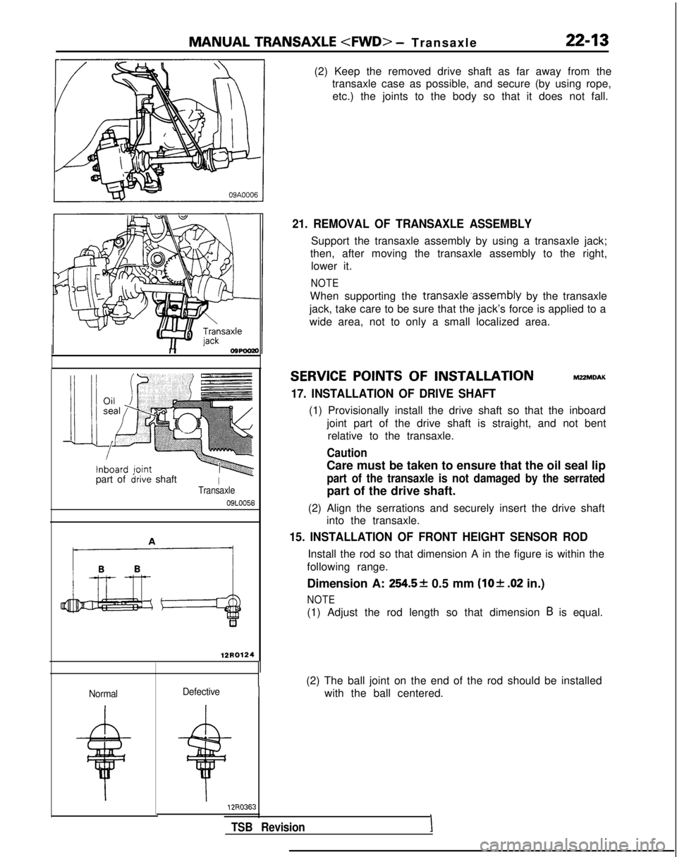
17. INSTALLATION OF DRIVE SHAFT
(1) Provisionally install the drive shaft so that the inboard
joint part of the drive shaft is straight, and not bentrelative to the transaxle.
Caution
Care must be taken to ensure that the oil seal lip
part of the transaxle is not damaged by the serrated
part of the drive shaft.
(2) Align the serrations and securely insert the drive shaft into the transaxle.
15. INSTALLATION OF FRONT HEIGHT SENSOR ROD
Install the rod so that dimension A in the figure is within the
following range.
Dimension A:
254.5* 0.5 mm (lo& .02 in.)
NOTE
(1) Adjust the rod length so that dimension B is equal.
(2) The ball joint on the end of the rod should be installed with the ball centered.
Defective
I
Page 679 of 1273

MANUAL TRANSAXLE - SDecifications2245
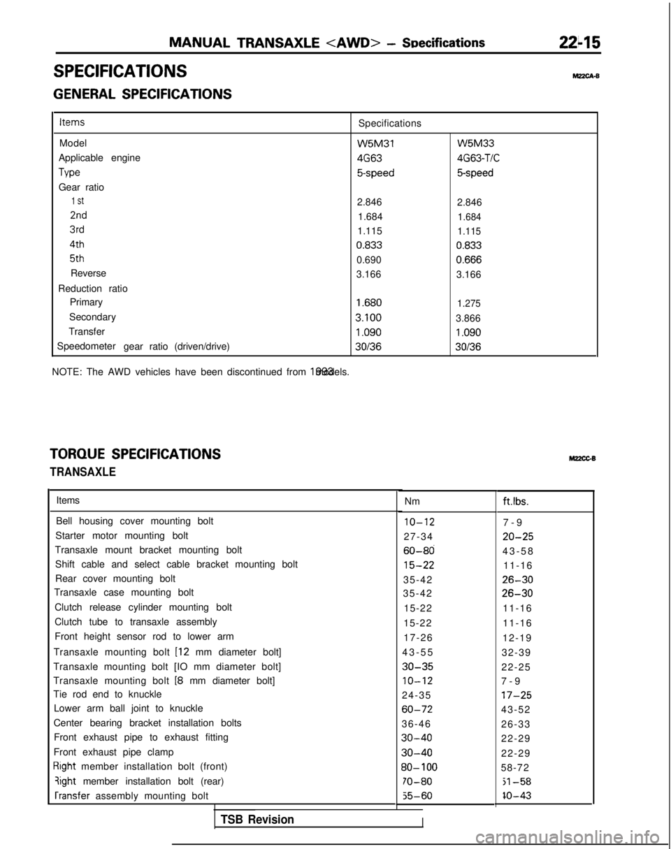
SPECIFICATIONSM?zcA-B
GENERAL SPECIFICATIONSItems
Specifications
Model W5M31
Applicable engine 4G63
Tvw
5-speed
Gear ratio
1 St2.846
2nd1.684
3rd1.115 4th
0.833
5th
0.690
Reverse 3.166
Reduction ratio Primary
1.680
Secondary 3.100
Transfer
1.090
Speedometer gearratio(driven/drive)30136
NOTE: The AWD vehicles have been discontinued from 1993 models. W5M33
4G63-TIC
5-speed
2.846
1.684
1.115
0.833 0.666
3.166
1.275
3.866
1.090
30136
TORQUE SPECIFICATIONS
TRANSAXLE
Items
Bell housing cover mounting bolt
10-127-
9
Starter motor mounting bolt 27-34
20-25
Transaxle mount bracket mounting bolt60-8043-5
8
Shift cable and select cable bracket mounting bolt
15-2211-16
Rear cover mounting bolt 35-42
26-30
Transaxle case mounting bolt 35-4226-30
Clutch release cylinder mounting bolt 15-2211-16
Clutch tube to transaxle assembly 15-2211-16
Front height sensor rod to lower arm 17-2612-19
Transaxle mounting bolt
[I2 mm diameter bolt] 43-5
5
32-39
Transaxle mounting bolt [IO mm diameter bolt]
30-3522-25
Transaxle mounting bolt
18 mm diameter bolt]IO-127-
9
Tie rod end to knuckle 24-35
17-25
Lower arm ball joint to knuckle60-7243-52
Center bearing bracket installation bolts 36-4626-33
Front exhaust pipe to exhaust fitting
30-4022-29
Front exhaust pipe clamp
30-4022-29
Right member installation bolt (front)30- 10058-72
qight member installation bolt (rear)70-80jl-58 rransfer
assembly mounting bolt
55-60IO-43
Nm M22CGBft.lbs.
TSB RevisionI