Page 767 of 1273
AUTOMATIC TRANSAXLE - Troubleshooting
TAILLIGHT
RELAY
I334m6678
____-__-_--__-----------2 c-43
01OA
@
c-01"'&,"'$,5‘r
AUTO-CRUISECDWROL-UNIT
(RG)@ (GL)
1 9
g (GR)I 'f% I
3 I
C-16
1OA 1
-1
!I ”
5
5
>
1
3
5
5
e
'8 C-32
D-47
POWER/
ECONOMY CHANGE OVER
SWITCH
1
J/B(TAIL)
IPOYER
BY 12,
RLBW 1::s"/I-
;B li:m ki
YR5
(RG) 17<
ELC4-SPEEDAUTOMATIC
FGEt;;kE
MODULE
REMARK
tMARK INDICATES THE OPTIONAL WIRINGHARNESS FOR AUTO-CRUISE CONTROL SYSTEM.
TSB Revision\
Page 770 of 1273
23-64AUTOMATIC TRANSAXLE - Troubleshooting
CIRCUIT DIAGRAM
< 1990 models>
IGNITION
WCH
I
A-09
@
RK/
,_________ -_----__----
L '/p Lo\
J ,"
-LB!f#kONp SWITCH
'*IA-43
a
il-'jR2 -o,-wdRN
Ej2'7 5 113
P
(BY)
(RL)
(BW)
(Y)
(YB)
(YR)
tI I II IBY @
I-I 1
!RL @
Bw @Y
YB $j
YR @
I
R
N
EEi
D
2
II
1 IIai
t5w ,113
Y :tS
:( 2',YB) 114:( 6(YR) J 5IIE.,12E -51I:: 1II
P4
+<
_____--_---__-------
I510COMBINATIONiMETER
;zi
mc:
4
4
L
2E3
I
ciI
t
STARTER
MOTOR BACK-UP LIGHT
X35-AC-HOTOWNY
TSB Revision
Page 774 of 1273
AUTOMATIC TRANSAXLE - Troubleshooting
CIRCUIT DIAGRAM
< 1990.5 models>
IGNITION
YETFHI
IGNITION
%YCH
I
A-09 v1(i)
@j
3
4.J",,ll__-----.-----
2 LB a
0*4lx 10
i3%L
I \L-x
(BY)
(RL)
(BW)_... I
O/DII:( 2(YB) :(14(YM) I 14i6(YR) x 5 1 (YR) 1IcIYR G
_..__- ./"I
A-a,?
J.3: 1-1I1 (GL)If .TII ,Prl\
.12 6d j 1 (RG)--g
, \"K,
4R
COMBINATION.-
%
ziz.
m
BACK-UP LIGHT
35-AC-HOTlO-NY
TSB RevisionI
Page 778 of 1273
AUTOMATIC TRANSAXLE - Troubleshooting
CIRCUIT DIAGRAM
,<1991 and 1992 models>
II1II
I
IIIII
I
I
I
I
I
I
1I
I
1lII
I
I
I
I
I
IIIIII -IIII
R mw
IGNITION
W"
I
le 5
Bl
33 m
c;Efc-u
IGNITION
%F"
I
E,,I2 &$I(RG)(RG) @
I(GL)
P(GR) 8
a
I I’-----s-ee-m----__--w-s-______--------------J______ ----- ---. ------
, 10fO’OH$AT I ON
;;@g x,2+
%;.BY43
ii
cl9
7BACK-UP LIGHT
STARTERMOTOR
TSB Revision
Page 791 of 1273

AUTOMATIC TRANSAXLE - Service Adjustment Procedures23-85
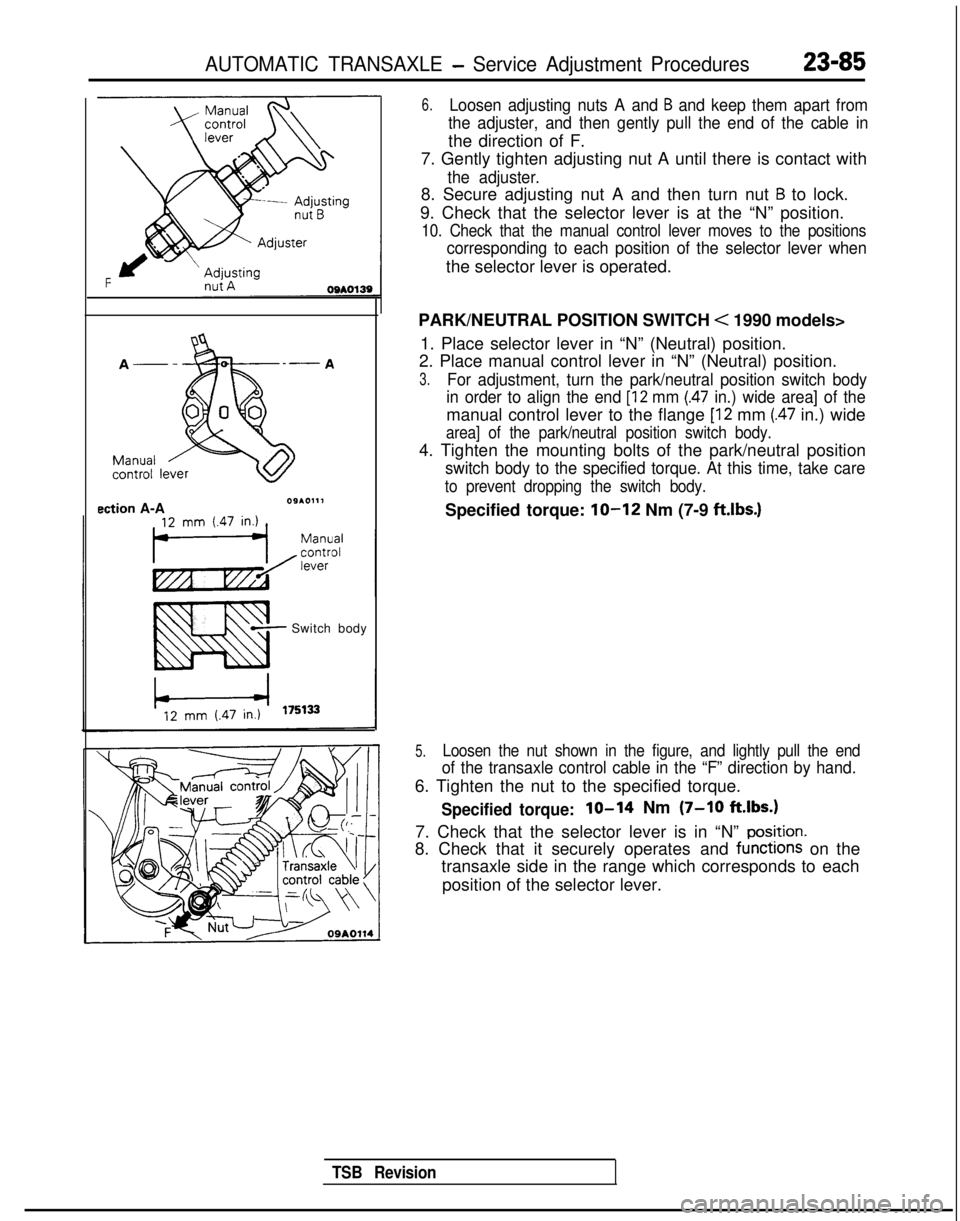
ection A-A09*0111
Switch body
6.Loosen adjusting nuts A and B and keep them apart from
the adjuster, and then gently pull the end of the cable in
the direction of F.
7. Gently tighten adjusting nut A until there is contact with
the adjuster.
8. Secure adjusting nut A and then turn nut B to lock.
9. Check that the selector lever is at the “N” position.
10. Check that the manual control lever moves to the positions
corresponding to each position of the selector lever when
the selector lever is operated.
PARK/NEUTRAL POSITION SWITCH
< 1990 models>
1. Place selector lever in “N” (Neutral) position.
2. Place manual control lever in “N” (Neutral) position.
3.For adjustment, turn the park/neutral position switch body
in order to align the end
[12 mm (.47 in.) wide area] of the
manual control lever to the flange [I2 mm (.47 in.) wide
area] of the park/neutral position switch body.
4. Tighten the mounting bolts of the park/neutral position
switch body to the specified torque. At this time, take care
to prevent dropping the switch body.
Specified torque: lo-12 Nm (7-9 ft.lbs.)
5.Loosen the nut shown in the figure, and lightly pull the end
of the transaxle control cable in the “F” direction by hand.
6. Tighten the nut to the specified torque.
Specified torque:lo-14 Nm (7-10 ft.lbs.)
7. Check that the selector lever is in “N” po?ition.
8. Check that it securely operates and functions on the
transaxle side in the range which corresponds to each
position of the selector lever.
TSB Revision
Page 792 of 1273

23-86AUTOMATIC TRANSAXLE -Service Adjustment Procedures
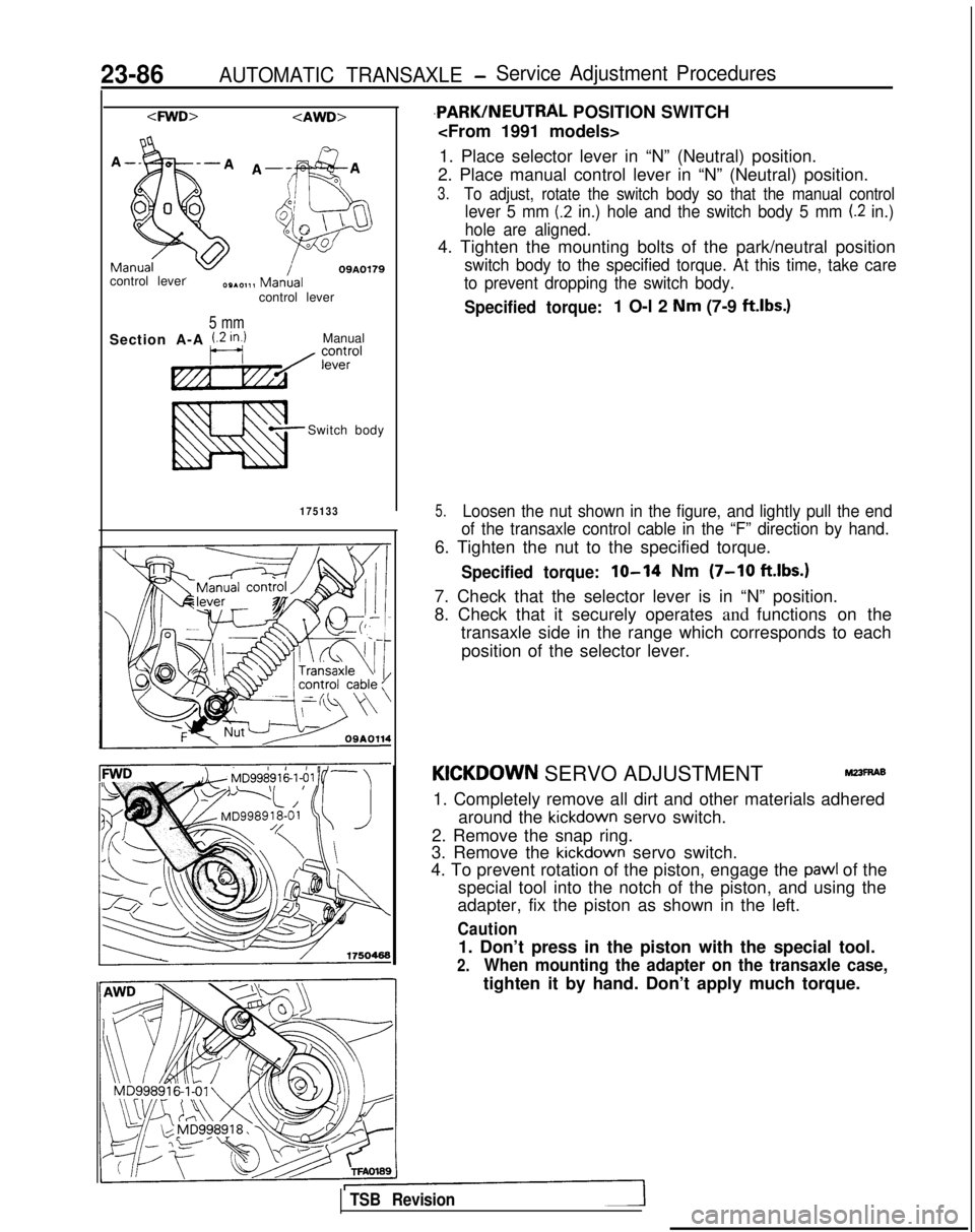
09A0179control lever
control lever
5 mm
Section A-A i.2 in.)Manual
Switch body
175133
,PARK/NEUTRAL POSITION SWITCH
1. Place selector lever in “N” (Neutral) position.
2. Place manual control lever in “N” (Neutral) position.
3.To adjust, rotate the switch body so that the manual control
lever 5 mm (.2 in.) hole and the switch body 5 mm (.2 in.)
hole are aligned.
4. Tighten the mounting bolts of the park/neutral position
switch body to the specified torque. At this time, take care
to prevent dropping the switch body.
Specified torque:1 O-l 2 Nm (7-9 ftlbs.)
5.Loosen the nut shown in the figure, and lightly pull the end
of the transaxle control cable in the “F” direction by hand.
6. Tighten the nut to the specified torque.
Specified torque:lo-14 Nm (7-10 ft.lbs.1
7. Check that the selector lever is in “N” position.
8. Check that it securely operates and functions on the
transaxle side in the range which corresponds to each
position of the selector lever.
KICKDOWN SERVO ADJUSTMENTr&?3~6
1. Completely remove all dirt and other materials adhered around the
kickdown servo switch.
2. Remove the snap ring.
3. Remove the
kickdown servo switch.
4. To prevent rotation of the piston, engage the
pawl of the
special tool into the notch of the piston, and using the
adapter, fix the piston as shown in the left.
Caution
1. Don’t press in the piston with the special tool.
2.When mounting the adapter on the transaxle case,
tighten it by hand. Don’t apply much torque.
TSB Revision
Page 803 of 1273

AUTOMATIC TRANSAXLE - Transaxle Control23-97
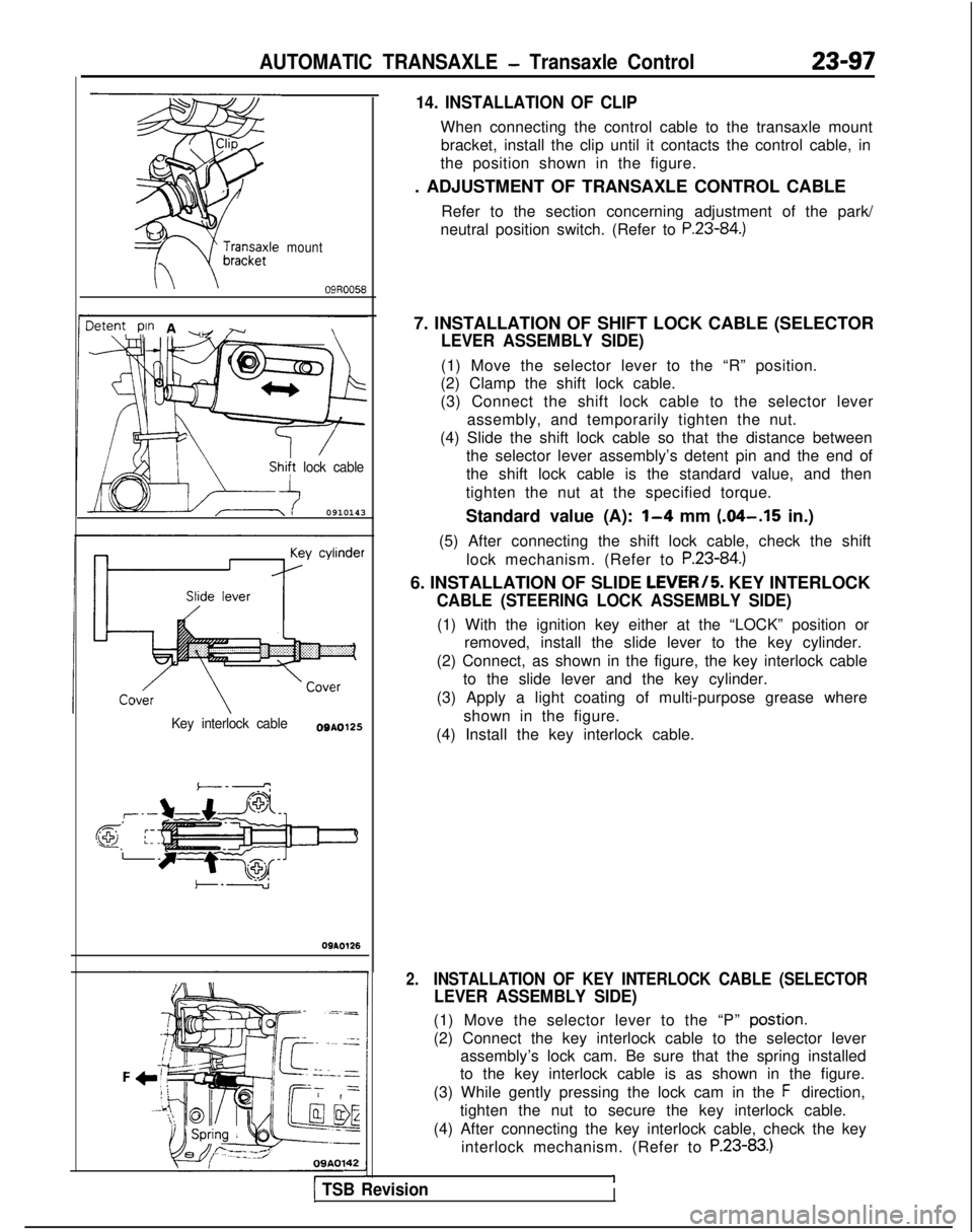
mount
\09R0058
3tent pin A ~ r\,I, ./
/
lock cable
0910143
Key interlock cableO0A0125
,T’--
@ ;:-.-
09AO126
09A0142
14. INSTALLATION OF CLIP
When connecting the control cable to the transaxle mount
bracket, install the clip until it contacts the control cable, in
the position shown in the figure.
. ADJUSTMENT OF TRANSAXLE CONTROL CABLE
Refer to the section concerning adjustment of the park/
neutral position switch. (Refer to
P.23-84.)
7. INSTALLATION OF SHIFT LOCK CABLE (SELECTOR
LEVER ASSEMBLY SIDE)
(1) Move the selector lever to the “R” position.
(2) Clamp the shift lock cable.
(3) Connect the shift lock cable to the selector lever
assembly, and temporarily tighten the nut.
(4) Slide the shift lock cable so that the distance between the selector lever assembly’s detent pin and the end of
the shift lock cable is the standard value, and then
tighten the nut at the specified torque.
Standard value (A):
1-4 mm (.04-.15 in.)
(5) After connecting the shift lock cable, check the shift lock mechanism. (Refer to
P.23-84.)
6. INSTALLATION OF SLIDE LEVERI5. KEY INTERLOCK
CABLE (STEERING LOCK ASSEMBLY SIDE)
(1) With the ignition key either at the “LOCK” position orremoved, install the slide lever to the key cylinder.
(2) Connect, as shown in the figure, the key interlock cable to the slide lever and the key cylinder.
(3) Apply a light coating of multi-purpose grease where shown in the figure.
(4) Install the key interlock cable.
2.INSTALLATION OF KEY INTERLOCK CABLE (SELECTOR
LEVER ASSEMBLY SIDE)
(1) Move the selector lever to the “P” postion.
(2) Connect the key interlock cable to the selector lever assembly’s lock cam. Be sure that the spring installed
to the key interlock cable is as shown in the figure.
(3) While gently pressing the lock cam in the
F direction,
tighten the nut to secure the key interlock cable.
(4) After connecting the key interlock cable, check the key interlock mechanism. (Refer to
P.23-83.)
11 TSB RevisionI
Page 813 of 1273

AUTOMATIC TRANSAXLE - Transaxle Assembly 23407
OSAOl82
Hub
SERVICE POINTS OF REMOVAL MZ3LMU
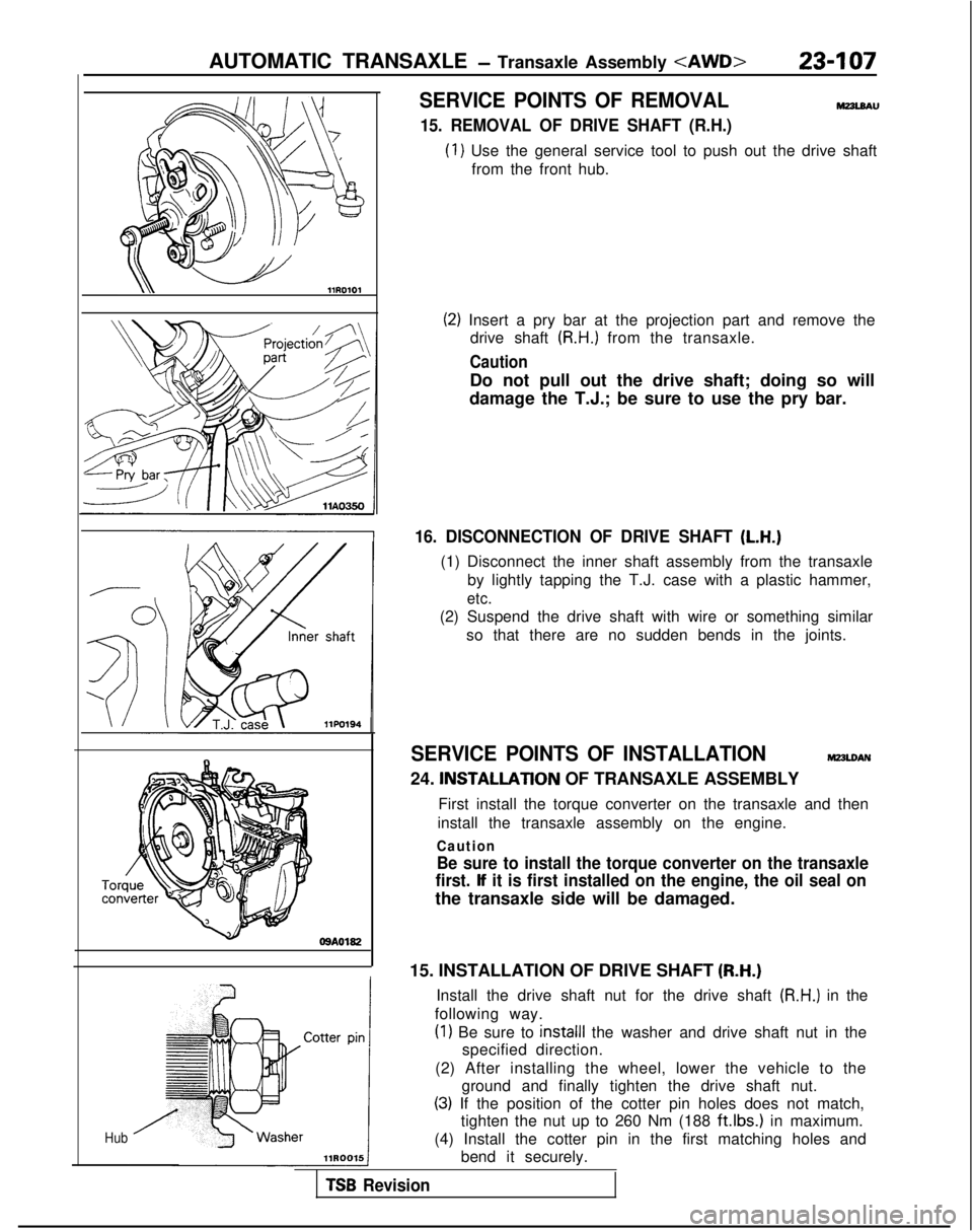
15. REMOVAL OF DRIVE SHAFT (R.H.)
(1) Use the general service tool to push out the drive shaft
from the front hub.
(2) Insert a pry bar at the projection part and remove the drive shaft
(R.H.) from the transaxle.
Caution
Do not pull out the drive shaft; doing so will
damage the T.J.; be sure to use the pry bar.
16. DISCONNECTION OF DRIVE SHAFT (L.H.)
(1) Disconnect the inner shaft assembly from the transaxle
by lightly tapping the T.J. case with a plastic hammer,
etc.
(2) Suspend the drive shaft with wire or something similarso that there are no sudden bends in the joints.
SERVICE POINTS OF INSTALLATIONMZ3LOAN
24. INSTALLAnON OF TRANSAXLE ASSEMBLY
First install the torque converter on the transaxle and then
install the transaxle assembly on the engine.
Caution
Be sure to install the torque converter on the transaxle
first.
lf it is first installed on the engine, the oil seal on
the transaxle side will be damaged.
15. INSTALLATION OF DRIVE SHAFT
(R-H.)
Install the drive shaft nut for the drive shaft (R.H.) in the
following way.
(1) Be sure to install1 the washer and drive shaft nut in the
specified direction.
(2) After installing the wheel, lower the vehicle to the ground and finally tighten the drive shaft nut.
(3) If the position of the cotter pin holes does not match,tighten the nut up to 260 Nm (188
ft.lbs.1 in maximum.
(4) Install the cotter pin in the first matching holes and bend it securely.
TSB Revision