1989 MITSUBISHI GALANT light
[x] Cancel search: lightPage 847 of 1273
FRONT AXLE -Drive Shaft (T.J.-R.J.
Type)26-17
INSPECTIONM26OGBC
l Check the drive shaft for damage, bending or corrosion.
l Check the drive shaft
splines for wear or damage.
lCheck for entry of water and/or foreign material into R.J.
l Check the spider assembly for roller rotation, wear or
corrosion.
lCheck the groove inside T.J. case for wear or corrosion.
l Check the boots for deterioration, damage or cracking.
SERVICE POINTS OF REASSEMBLY
MZbOHBE
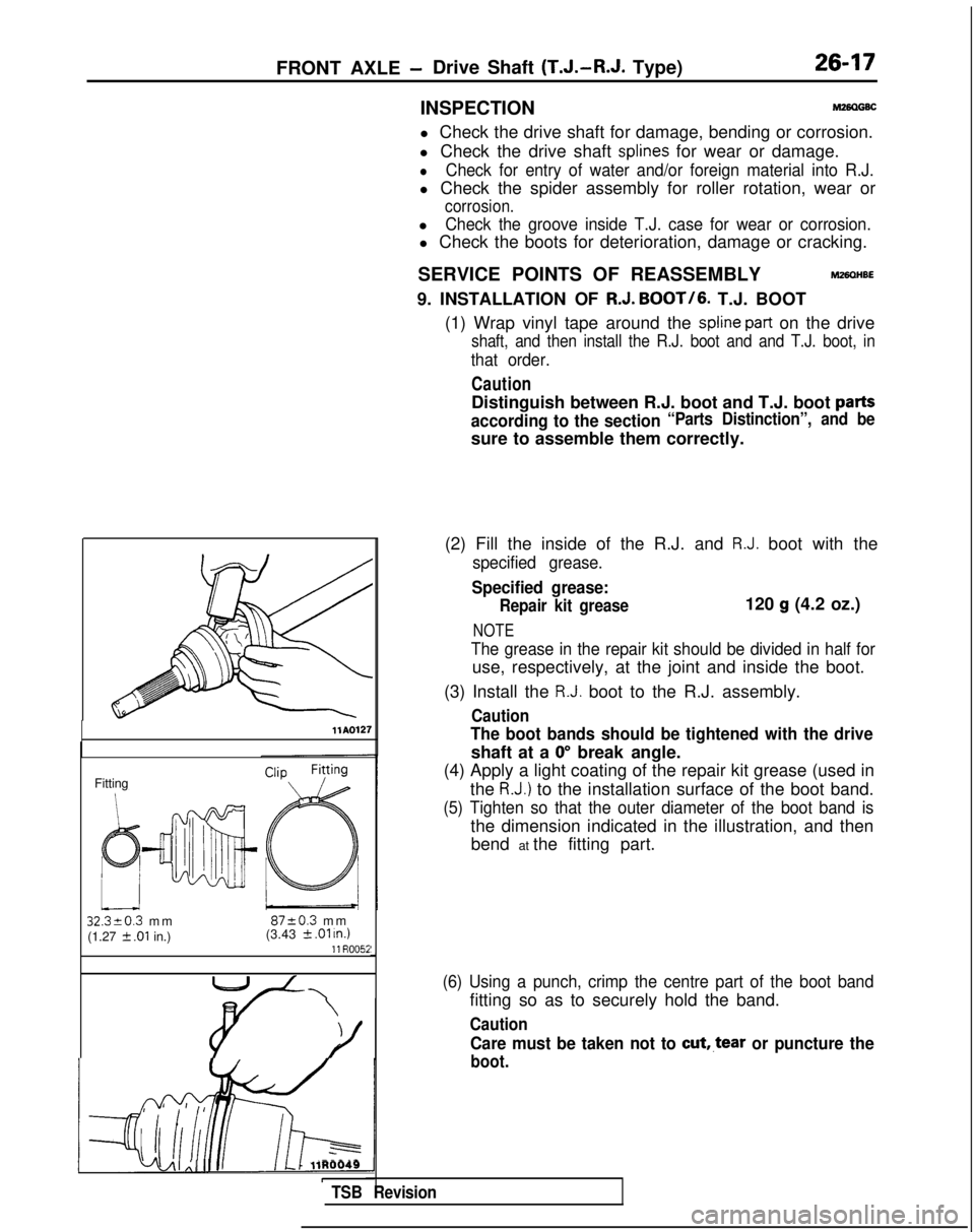
9. INSTALLATION OF R.J. BOOT/6.
T.J. BOOT
(1) Wrap vinyl tape around the
spline part on the drive
shaft, and then install the R.J. boot and and T.J. boot, in
that order.
Caution
Distinguish between R.J. boot and T.J. boot parts
according to the section“Parts Distinction”, and be
sure to assemble them correctly.
llAQl27
Fitting
32320.3 m
m
8720.3 m
m
(1.27
2 .Ol in.) (3.43 k .Ol u7.111 R005i
i-lj4AI Al II III L-1 llR0049ITSB Revision
(2) Fill the inside of the R.J. and R.J. boot with the
specified grease.
Specified grease:
Repair kit grease120 g (4.2 oz.)
NOTE
The grease in the repair kit should be divided in half for
use, respectively, at the joint and inside the boot.
(3) Install the
R.J. boot to the R.J. assembly.
Caution
The boot bands should be tightened with the drive
shaft at a 0” break angle.
(4) Apply a light coating of the repair kit grease (used in
the
R.J.) to the installation surface of the boot band.
(5) Tighten so that the outer diameter of the boot band is
the dimension indicated in the illustration, and thenbend at the fitting part.
(6) Using a punch, crimp the centre part of the boot band
fitting so as to securely hold the band.
Caution
Care must be taken not to cut,.tear or puncture the
boot.
Page 848 of 1273
26-18FRONT AXLE - Drive Shaft (T.J.-R.J.
Type)
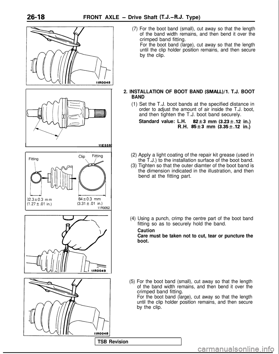
(7) For the boot band (small), cut away so that the length
of the band width remains, and then bend it over the
crimped band fitting.
For the boot band (large), cut away so that the length
until the clip holder position remains, and then secure
by the clip.
Fitting 32.3kO.3
mm
(I .27 t .Ol in.) llR0052
2. INSTALLATION OF BOOT BAND (SMALL)/l.
T.J. BOOT
BAND
(1) Set the T.J. boot bands at the specified distance in
order to adjust the amount of air inside the T.J. boot,
and then tighten the T.J. boot band securely.
Standard value: L.H.82+3 mm (3.23k.12
in.)
R.H.
85+3 mm (3.35f.12 in.)
(2) Apply a light coating of the repair kit grease (used in the T.J.) to the installation surface of the boot band.
(3) Tighten so that the outer diamter of the boot band is the dimension indicated in the illustration, and thenbend at the fitting part.
(4) Using a punch, crimp the centre part of the boot band
fitting so as to securely hold the band.
Caution
Care must be taken not to cut, tear or puncture the
boot.
(5) For the boot band (small), cut away so that the length of the band width remains, and then bend it over the
crimped band fitting.
For the boot band (large), cut away so that the length
until the clip holder position remains, and then secure
by the clip.
TSB Revision
Page 854 of 1273
26-24FRONT AXLE - Drive Shaft
C
I1
c
1:
9
M8
Pry barTrarkaxlellE526
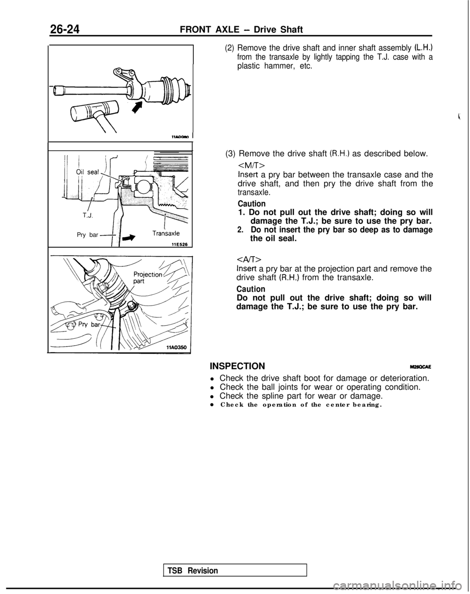
(2) Remove the drive shaft and inner shaft assembly (L.H.)
from the transaxle by lightly tapping the T.J. case with a
plastic hammer, etc.
(3) Remove the drive shaft (R.H.) as described below.
drive shaft, and then pry the drive shaft from the
transaxle.
Caution
1. Do not pull out the drive shaft; doing so will damage the T.J.; be sure to use the pry bar.
2.Do not insert the pry bar so deep as to damage
the oil seal.
Inset-t a pry bar at the projection part and remove the
drive shaft
(R.H.) from the transaxle.
Caution
Do not pull out the drive shaft; doing so will
damage the T.J.; be sure to use the pry bar.
INSPECTION l Check the drive shaft boot for damage or deterioration.
l Check the ball joints for wear or operating condition.
l Check the spline part for wear or damage.
l Check the operation of the center bearing.
TSB Revision
Page 879 of 1273
REAR AXLE
Trailing arm
/MB990938-01
Trailing arm MB990799-01
llAOO40
11 A0033
Outer bearing
Seal lip
surfac’111026
SERVICE POINTS OF INSTALLATIONW7HDAQ
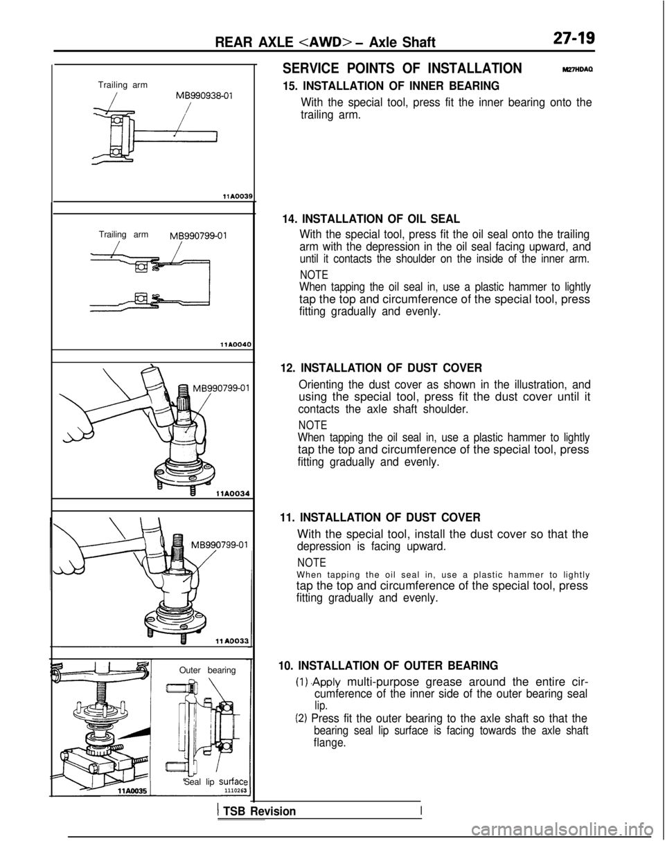
15. INSTALLATION OF INNER BEARING
With the special tool, press fit the inner bearing onto the
trailing arm.
14. INSTALLATION OF OIL SEAL
With the special tool, press fit the oil seal onto the trailing
arm with the depression in the oil seal facing upward, and
until it contacts the shoulder on the inside of the inner arm.
NOTE
When tapping the oil seal in, use a plastic hammer to lightly
tap the top and circumference of the special tool, press
fitting gradually and evenly.
12. INSTALLATION OF DUST COVER
Orienting the dust cover as shown in the illustration, and
using the special tool, press fit the dust cover until it
contacts the axle shaft shoulder.
NOTE
When tapping the oil seal in, use a plastic hammer to lightly
tap the top and circumference of the special tool, press
fitting gradually and evenly.
11. INSTALLATION OF DUST COVER
With the special tool, install the dust cover so that the
depression is facing upward.
NOTE
When tapping the oil seal in, use a plastic hammer to lightl
y
tap the top and circumference of the special tool, press
fitting gradually and evenly.
10. INSTALLATION OF OUTER BEARING
(1) .Apply multi-purpose grease around the entire cir-
cumference of the inner side of the outer bearing seal
lip.
(2) Press fit the outer bearing to the axle shaft so that the
bearing seal lip surface is facing towards the axle shaft
flange.
1 TSB RevisionI
Page 905 of 1273
31-6WHEEL AND TIRE - Wheel and Tire
INSTRUCTIONS FOR ALUMINUM TYPE WHk&g
1. Aluminum is vulnerable to alkalies. If
a vehicle washing
detergent has been used, or salt from sea water or road
chemicals has adhered, wash the vehicle as soon as
possible. After washing the vehicle, apply body or wheel
wax to the aluminum type wheels to prevent corrosion.
2.When cleaning the vehicle with steam, do not direct steam
onto the aluminum type wheels.
When tightening nuts for aluminum type wheels, particular- ly observe the following:
(I) Clean the hub surface of aluminum type wheels.
(2) After finger-tightening wheel nuts, tighten them to specifications.
(3) Do not use an impact wrench or push the wrench by foot to tighten the wheel nuts.
(4) Do not apply oil to the threaded portions.
INSTRUCTIONS FOR TIRE CHAINS AND SNOW
TIRES M31GGbl
1.Use tire chains only on front wheels. Do not use tire chains
on rear wheels.
2. When using snow tires, use them on all four wheels for maneuverability and safety.
INSTRUCTIONS FOR COMPACT SPARE TlR,E,,,,
1. The compact spare tire is designed to save space in theluggage compartment, and its lighter weight makes it
easier to use if a flat tire occurs.
2.The following instructions for the compact spare tire should be observed.
(1) Check the inflation pressure after installing the spare, and adjust to the specified pressure.
(2) Avoid driving through automatic car washes and over obstacles that could possibly damage the vehicle’s
undercarriage. Because the tire is smaller than the
original tire, car ground clearance is slightly reduced.
(3) The compact spare tire should not be used on any other wheels, nor should standard tires, snow tires, wheel
covers or trim rings be used with the compact spare
wheel. If such use is attempted, damage to these items
or other vehicle components may occur.
TSB Revision
Page 940 of 1273
339-l
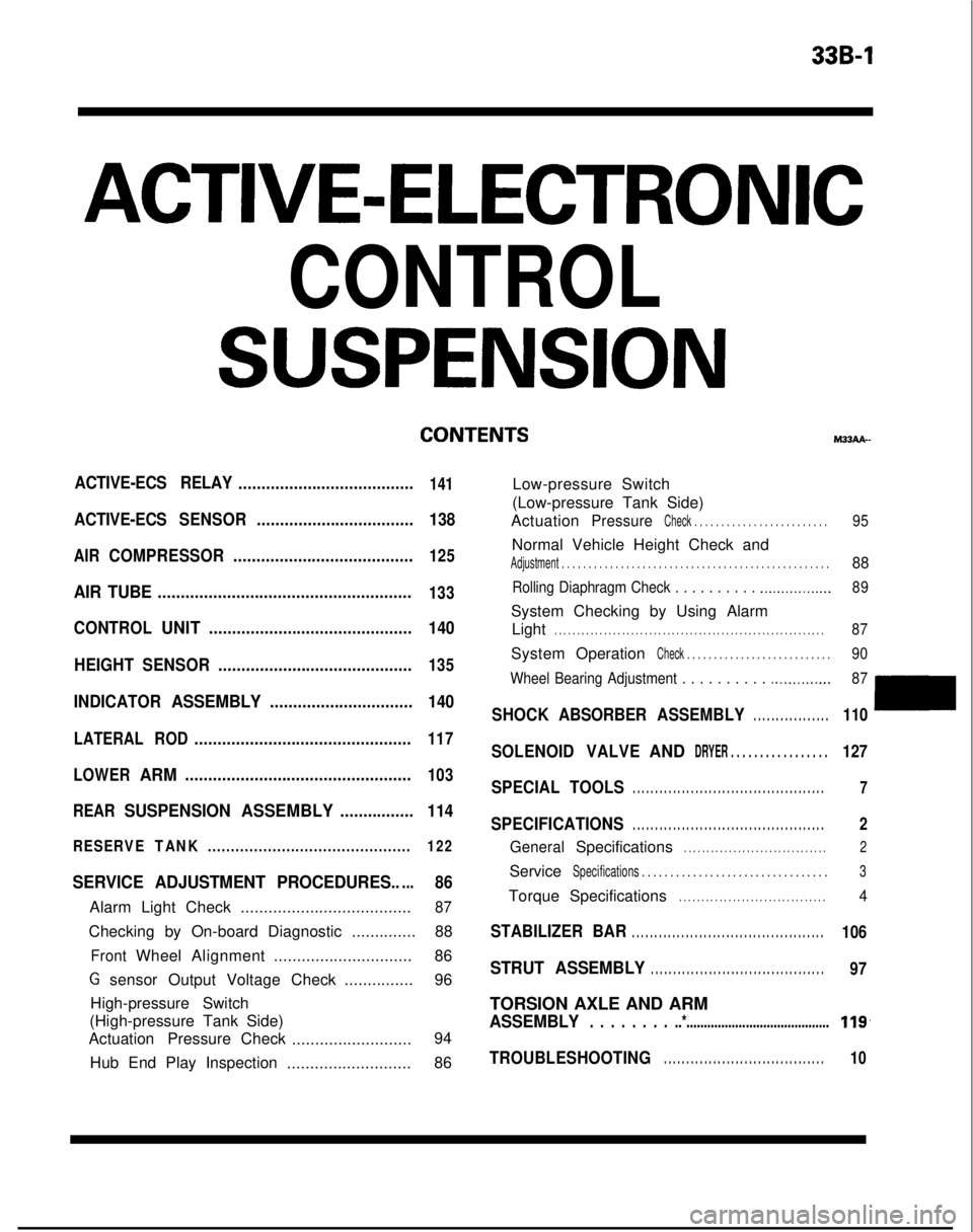
ACTIVE-ELECTRONIC
CONTROL
SUSPENSION
ACTIVE-ECS RELAY......................................141
ACTIVE-ECSSENSOR.................................. 138
AIRCOMPRESSOR.......................................125
AIR TUBE.......................................................133
CONTROLUNIT............................................ 140
HEIGHT SENSOR ..........................................
135
INDICATORASSEMBLY............................... 140
LATERALROD...............................................117
LOWER
ARM.................................................103
REAR
SUSPENSION ASSEMBLY................114
RESERVETANK............................................ 122
SERVICE ADJUSTMENT PROCEDURES.....86
Alarm Light Check.....................................87
Checking by On-board Diagnostic ..............88
FrontWheelAlignment .............................. 86
G sensor Output Voltage Check ...............96
High-pressure Switch
(High-pressure Tank Side)
Actuation Pressure Check
.......................... 94
Hub End Play Inspection ...........................86 M33AA-
Low-pressure Switch
(Low-pressure Tank Side)
Actuation
PressureCheck . . . . . . . . . . . . . . . . . . . . . . . . .95
Normal Vehicle Height Check and
Adjustment . . . . . . . . . . . . . . . . . . . . . . . . . . . . . . .\
. . . . . . . . . . . . . . . . . . .88
Rolling Diaphragm Check . . . . . . . . . . .._.............. 89
System Checking by Using Alarm
Light
. . . . . . . . . . . . . . . . . . . . . . . . . . . . . . . . . . . . \
. . . . . . . . . . . . . . . . . . . . . . . .87
System OperationCheck . . . . . . . . . . . . . . . . . . . . . . . . . . .90
Wheel Bearing Adjustment . . . . . . . . . .
.._........... 87
SHOCKABSORBER ASSEMBLY. . . . . . . . . . . . . . . . .110
SOLENOIDVALVEANDDRYER . . . . . . . . . . . . . . . . .127
SPECIAL TOOLS. . . . . . . . . . . . . . . . . . . . . . . . . . . . . . . . . . . . \
. . . . . . .7
SPECIFICATIONS. . . . . . . . . . . . . . . . . . . . . . . . . . . . . . . . . . . . \
. . . . . . .2
GeneralSpecifications. . . . . . . . . . . . . . . . . . . . . . . . . . . . . . . .2
ServiceSpecifications . . . . . . . . . . . . . . . . . . . . . . . . . . . . .\
. . . .3
TorqueSpecifications. . . . . . . . . . . . . . . . . . . . . . . . . . . . . . . . .4
STABILIZER BAR. . . . . . . . . . . . . . . . . . . . . . . . . . . . . . . . . . . . \
. . . . . . .106
STRUT ASSEMBLY. . . . . . . . . . . . . . . . . . . . . . . . . . . . . . . . . . . . \
. . .97
TORSION AXLE AND ARM
ASSEMBLY. . . . . . . . ..*.........................................119,
TROUBLESHOOTING. . . . . . . . . . . . . . . . . . . . . . . . . . . . . . . . . . . .10
Page 941 of 1273
33B-2ACTIVE-ELECTRONIC CONTROL SUSPENSION - Specifications
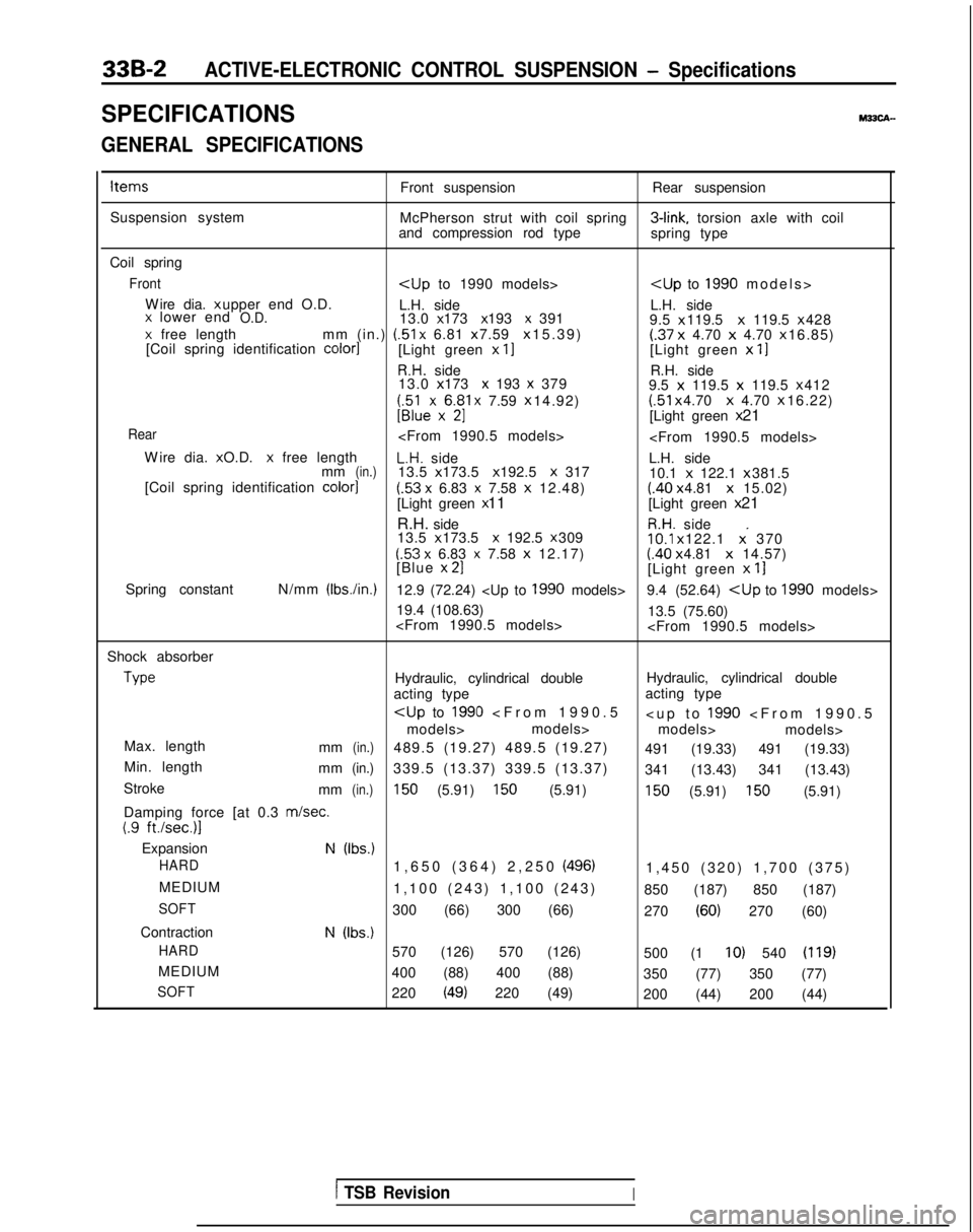
SPECIFICATIONSM33CA-
GENERAL SPECIFICATIONS
ItemsFront suspensionRear suspension
Suspension system McPherson strut with coil spring 3-link,
torsion axle with coil
and compression rod type spring type
Coil spring
Front
Wire dia. x upper end O.D.
L.H. side L.H. side
x lower endO.D.13.0 x 173 x 193 x 391
9.5 x 119.5 x
119.5 x 428x free length
mm (in.) (51
x 6.81 x 7.59 x 15.39)(.37
x
4.70 x 4.70 x 16.85)
[Coil spring identification color1[Light green x II[Light green x
11
R.H. side R.H. side
13.0 x 173 x 193 x 379
9.5 x
119.5 x
119.5 x 412
;;lexx6$1 x 7.59
x 14.92) (51
x 4.70 x
4.70 x 16.22)U[Light green
x 21
Rear
W
ire dia. x O.D.
x free lengthL.H. side
L.H. side
mm(in.)13.5 x 173.5 x 192.5 X 317
10.1 x
122.1 x 381.5
[Coil spring identification color]
(.53 x 6.83 x 7.58
x
12.48)(.40 x 4.81 x
15.02)
[Light green x 11
[Light green x 21
R.H. side
R.H. side
13.5 x 173.5 x 192.5 x 30910.1
x 122.1 x. 370(53 x 6.83 x 7.58
x
12.17)(.40 x 4.81 x
14.57)
[Blue x 21[Light green
x
11
Spring constant N/mm (Ibs./in.)12.9 (72.24)
19.4 (108.63) 13.5 (75.60)
Shock absorber Type
Hydraulic, cylindrical double
Hydraulic, cylindrical double
acting type acting type
models> models>
models> models>
Max. length mm
(in.)489.5 (19.27) 489.5 (19.27) 491 (19.33) 491 (19.33)
Min. length mm
(in.)339.5 (13.37) 339.5 (13.37) 341 (13.43) 341 (13.43)
Stroke mm
(in.)150 (5.91) 150 (5.91)150 (5.91) 150 (5.91)
Damping force [at 0.3
m/set.(.9 ft./sec.)l
ExpansionN (Ibs.)
HARD
1,650 (364) 2,250 (496)1,450 (320) 1,700 (375
)
MEDIUM 1,100 (243) 1,100 (243) 850 (187) 850 (187)
SOFT300 (66) 300 (66) 270 (60) 270 (60)
Contraction
N (Ibs.)
HARD
570 (126) 570 (126) 500 (1 IO) 540 (119)
MEDIUM400 (88) 400 (88) 350 (77) 350 (77)
SOFT220 (49) 220 (49)200 (44) 200 (44)
1 TSB RevisionI
Page 950 of 1273
ACTIVE-ELECTRONIC CONTROL SUSPENSION - Troubleshooting 33B-11
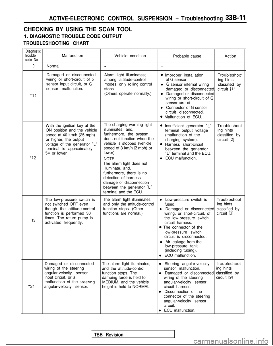
CHECKING BY USING THE SCAN TOOL
1. DIAGNOSTIC TROUBLE CODE OUTPUT
TROUBLESHOOTING CHART
DiagnostictroubleMalfunctionVehicle conditioncode No.Probable causeAction
0Normal---
Damaged or disconnected
Alarm light illuminates;0 Improper installation Troubleshoof
wiring or short-circuit of Gamong attitude-control of G sensor.
sensor input circuit, or Ging hints
modes, only rolling control
sensor malfunction. l
G sensor internal wiring
classified by
stops. damaged or disconnected. circuit
[I]
“11(Others operate normally.)l Damaged or disconnected
wiring or short-circuit of
G
sensor circurt.
l Connector of
G sensor
circuit disconnected.
0 Malfunction of ECU.
W
ith the ignition key at the
The charging warning light
ON position and the vehicle illuminates, and,
0 Insufficient generator “L”Troubleshoot
speed at 40 km/h (25 mph) furthermore, the system terminal output voltage
ing hints
or higher, the output does not function when the (malfunction of the
classified by
charging system). circuit
[2]
voltage of the generator ‘I”vehicle is stopped (vehicle0 Harness short-circuit
terminal is approximately speed of 3 km/h (2 mph) or
5V or lower
lower). between the generator“L” terminal and the ECU.“12
NOTEl ECU malfunction.
The alarm light does not illuminate, and,
furthermore, there is no
detection of harness
damage or disconnection
between the generator “L”
terminal and the ECU.
The low-pressure switch is The alarm light illuminates,
l Low-pressure switch is Troubleshoot
not switched OFF even and only the attitude-control
fused.
though the attitude-control ing hints
function stops. (Other l Damaged or disconnected classified by
function is performed 30 functions are normal.) circuit
131
13times. The return pump is wiring, or short-circuit, of
the low-pressure switch
activated frequently. circuit harness.
0 The connector of the
low-pressure switch
circuit is disconnected.
l Air leakage from the low-pressure tank
(including tubing).
l ECU malfunction.
“21
Damaged or disconnected The alarm light illuminates,l Steering angular-velocity Troubleshoot-
wiring of the steering and the attitude-control sensor malfunction.
angular-velocity sensor ing hints
function stops. The
input circuit, or a l Damaged or disconnected classified by
damping force is held to wiring of the steeringcircuit
191malfunction of the steenng
MEDIUM, and the vehicle
angular-velocity sensor. angular-velocity sensor
height is held to NORMAL circuit harness.
l Disconnection of the connector of the steering
angular-velocity sensor
circuit.
l ECU malfunction.
TSB Revision