Page 640 of 1273
17-20EMISSION CONTROL SYSTEMS -Evaporative Emission Control System
Engine speed (rpm)>
3FU262
E2id>
‘_/- )Engine
speed
(rpm)1 FU446
1 TSB Revision
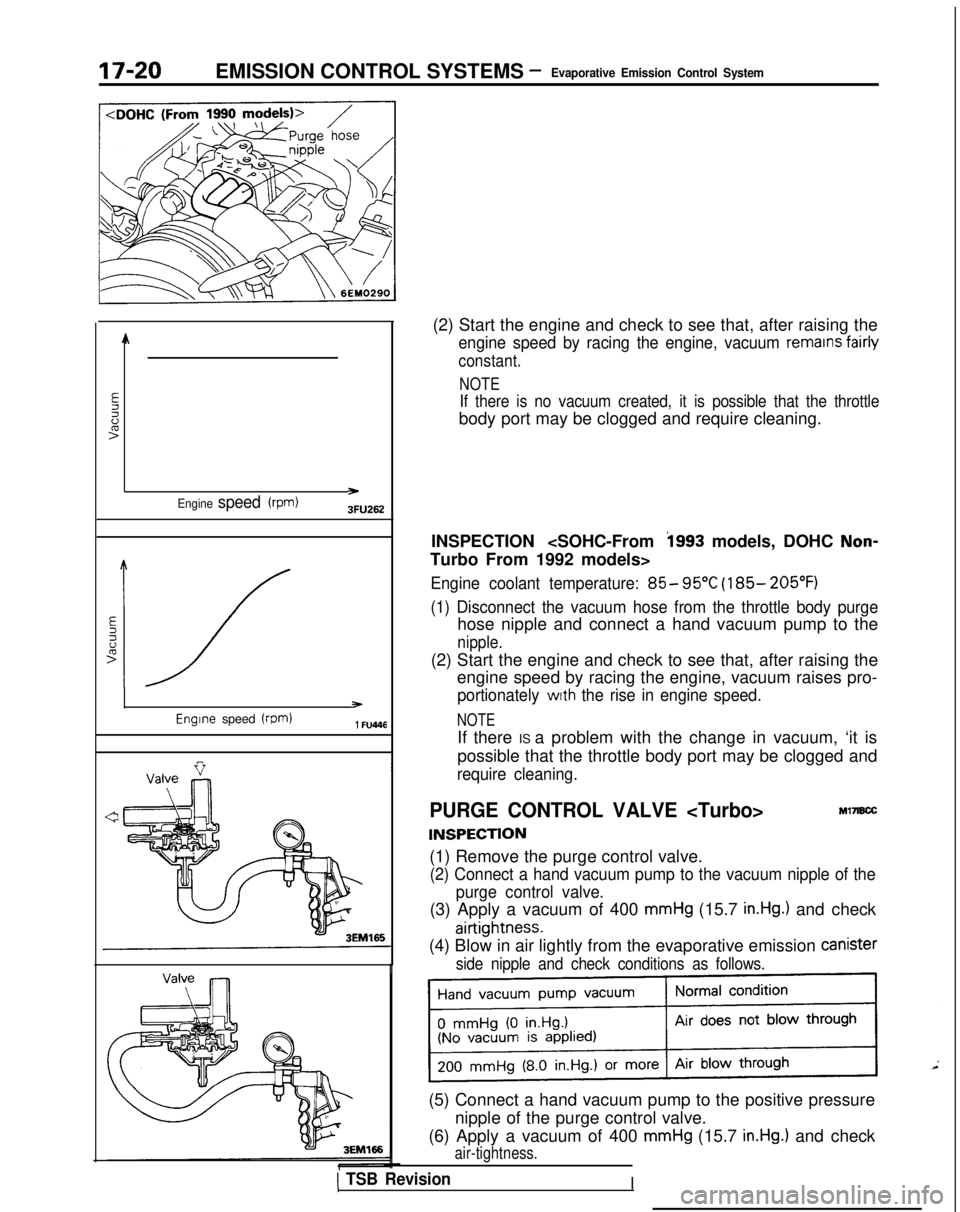
(2) Start the engine and check to see that, after raising the
engine speed by racing the engine, vacuum remains fairly
constant.
NOTE
If there is no vacuum created, it is possible that the throttle
body port may be clogged and require cleaning.
INSPECTION
i993 models, DOHC Non-
Turbo From 1992 models>
Engine coolant temperature: 85- 95°C (185- 205°F)
(1) Disconnect the vacuum hose from the throttle body purge
hose nipple and connect a hand vacuum pump to the
nipple.
(2) Start the engine and check to see that, after raising the engine speed by racing the engine, vacuum raises pro-
portionately with the rise in engine speed.
NOTE
If there IS a problem with the change in vacuum, ‘it is
possible that the throttle body port may be clogged and
require cleaning.
PURGE CONTROL VALVE
INSPECTION
Ml7B.X
(1) Remove the purge control valve.
(2) Connect a hand vacuum pump to the vacuum nipple of the
purge control valve.
(3) Apply a vacuum of 400 mmHg (15.7 in.Hg.) and check
airtightness.
(4) Blow in air lightly from the evaporative emission Canister
side nipple and check conditions as follows.
(5) Connect a hand vacuum pump to the positive pressure
nipple of the purge control valve.
(6) Apply a vacuum of 400
mmHg (15.7 in.Hg.) and check
air-tightness.
I
Page 645 of 1273
EMISSION CONTROL SYSTEMS -Exhaust Gas Recirculation (EGR) System17-25
1
.
EGR SYSTEM INSPECTION Ml7ICJF
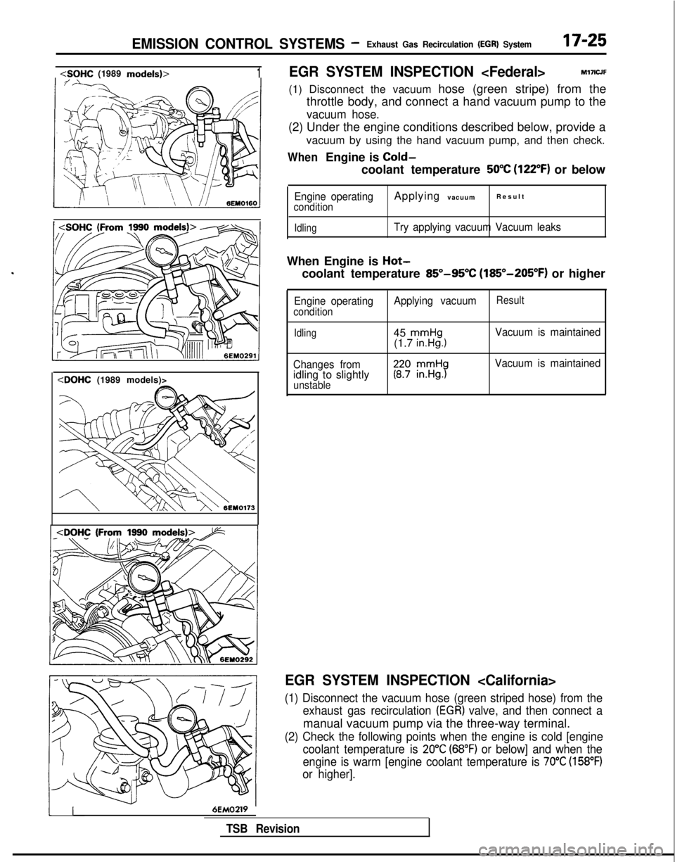
(1) Disconnect the vacuum hose (green stripe) from the throttle body, and connect a hand vacuum pump to the
vacuum hose.
(2) Under the engine conditions described below, provide a
vacuum by using the hand vacuum pump, and then check.
WhenEngine is Cold-
coolant temperature 50°C (122°F) or below
Engine operatingconditionApplying vacuumResul
t
IdlingTry applying vacuum Vacuum leaks
When Engine is Hot-
coolant temperature 85”-95°C (185”-205°F) or higher
Engine operatingconditionApplying vacuumResult
Idling45 mmHg(1.7 in.Hg.1Vacuum is maintained
Changes from
idling to slightlyunstable
Vacuum is maintained
EGR SYSTEM INSPECTION
(1) Disconnect the vacuum hose (green striped hose) from the exhaust gas recirculation
(EGR) valve, and then connect a
manual vacuum pump via the three-way terminal.
(2) Check the following points when the engine is cold [enginecoolant temperature is
20°C (68°F) or below] and when the
engine is warm [engine coolant temperature is
70°C (158°F)
or higher].
116EMOZW
TSB Revision
Page 674 of 1273
22-10MANUAL TRANSAXLE - Transaxl
e
TRANSAXLE
REMOVAL AND INSTALLATION
MZMA-A
27-34 Nm20-25 ft.lbs.
60-80
Nm*
43-58 ft.lbs.*
11-16
ft.lbs.71
11-16 ftlbs.
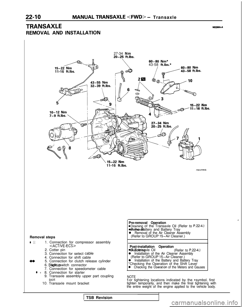
Removal steps
l *1, Connection for compressor assembly
2. Cotter pin
3. Connection for select cable
4. Connection for shift cable
a*5. Connection for clutch release cylinder
6. backup light switch connector
7. Connection for speedometer cable
l +8. Connection for starter
9. Transaxle assembly upper part coupling
tJ01t10. Transaxle mount bracket
Pre-removal Operation@Draining of the Transaxle Oil (Refer to P.22-4.) *Removal of the Battery and Battery Tray
l Removal of the Air Cleaner Assembly(Refer to GROUP 15-Air Cleaner.)
Post-installation Operation
asupplying of Transaxle Oil
(Refer to P.224.)l Installation of the Air Cleaner Assembly(Refer to GROUP 15-Air Cleaner.)l Installation of the Battery and Battery Tray*Checking the Operation of the Shift Leverl Checking the Ooeration of the Meters and Gauaes
NOTE
-t-or tightening locations indicated by the * symbol, firsttighten temporarily, and then make the final tightening with
the entire weight of the engine applied to the vehicle body.
1TSB Revision
Page 684 of 1273
22-20MANUAL TRANSAXLE - Transaxle
TRANSAXLE
REMOVAL AND INSTALLATIONMZMA-B
l Removal of the Battery and Battery Tray*Removal of the Air Cleaner Assembly
(Refer to GROUP 15-Air Cleaner.)
15-22
Nm11-16 ft.lbs.-
lo-12 Nm7-8 ft.lbs.;
Post-installation Operation@Supplying of Transaxle Oil (Refer to P.22-18.)l Installation of the Air Cleaner Assembly(Refer to GROUP 15-Air Cleaner.)*Installation of the Battery and BatteryTray*Checking the Operation of the ShiftLever*Checking the Operation of the Metersand Gauges
60-80
Nm*
27-34
Nm43-58ft.lbs.*
20-25ft.lbs.60-80Nm
43-55 Nm _
15-22’ Nm11-16 ft.lbs.
6
-15-22 Nm11-16 ftlbs.
09AOOS4
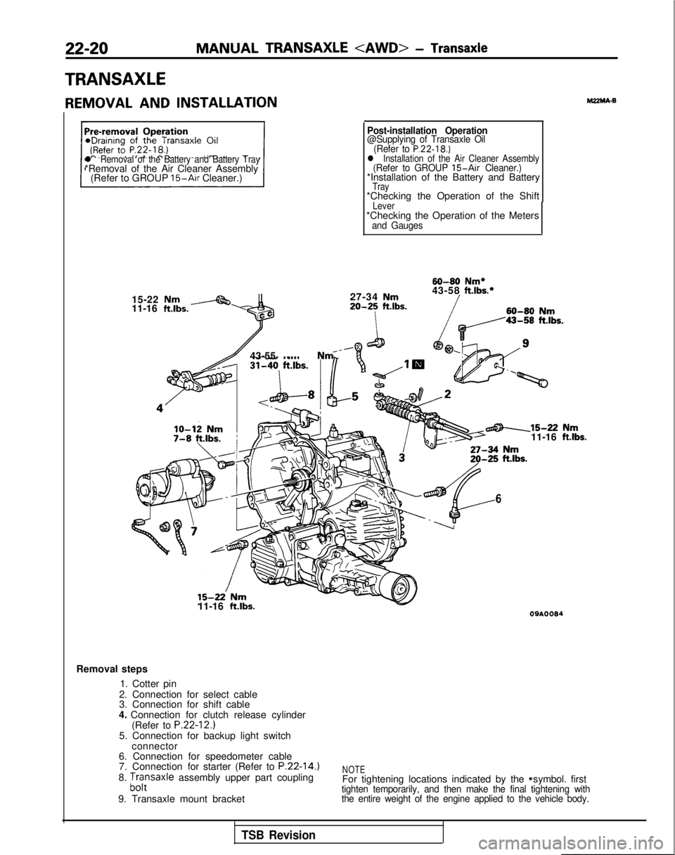
Removal steps
1. Cotter pin
2. Connection for select cable
3. Connection for shift cable
4. Connection for clutch release cylinder (Refer to
P.22-12.)5. Connection for backup light switchconnector
6. Connection for speedometer cable
7. Connection for starter (Refer to
P.22-14.)8. ;,,:saxle assembly upper part coupling
9. Transaxle mount bracketNOTEFor tightening locations indicated by the * symbol. firsttighten temporarily, and then make the final tightening with
the entire weight of the engine applied to the vehicle body.
TSB Revision
Page 686 of 1273
MANUAL TRANSAXLE - Transaxle
“\
)I
wb
I 1
\
I
1
M#
\\11Aoooo
SERVICE POINTS OF REMOVALM22MBAT
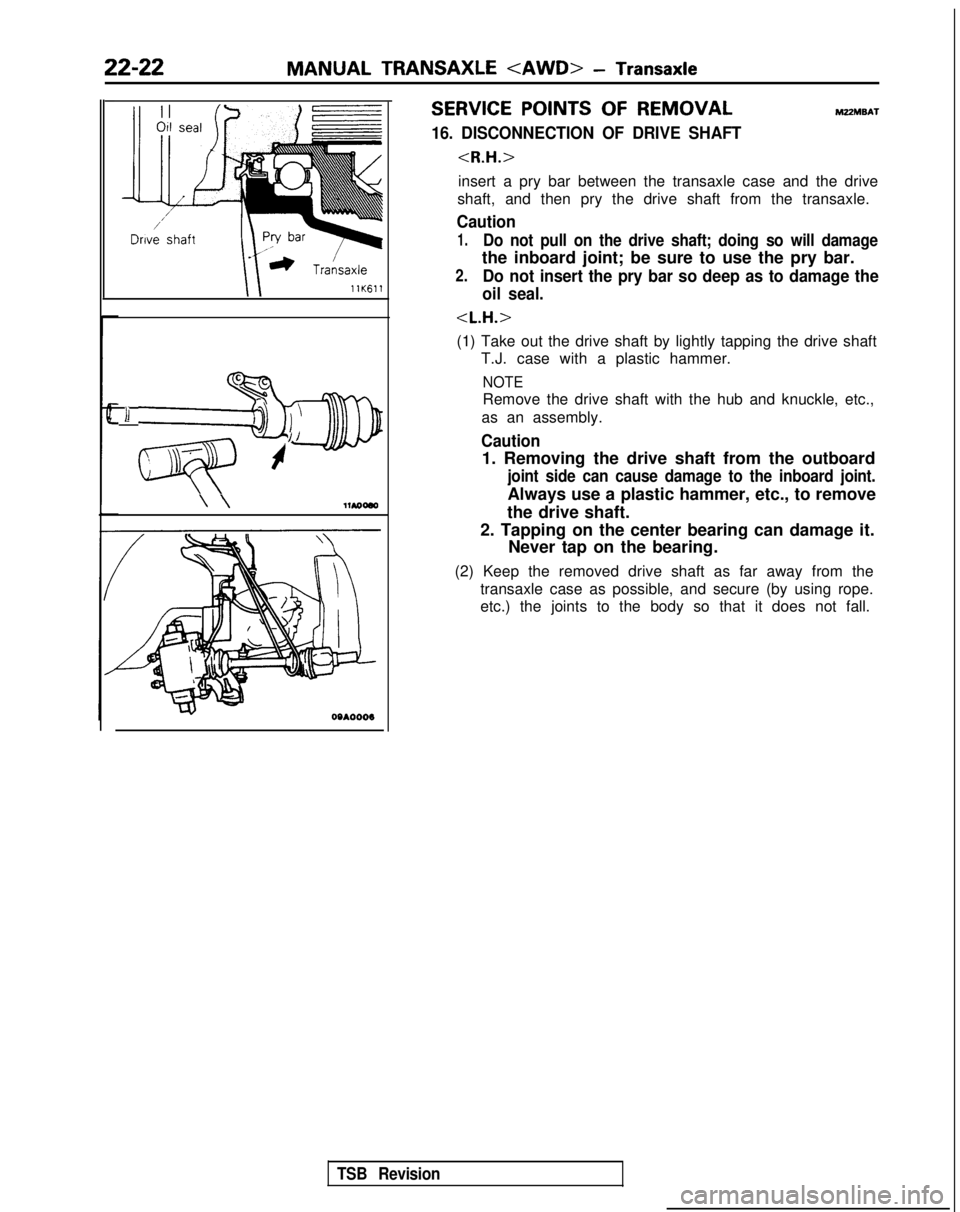
16. DISCONNECTION OF DRIVE SHAFT
insert a pry bar between the transaxle case and the drive
shaft, and then pry the drive shaft from the transaxle.
Caution
1.Do not pull on the drive shaft; doing so will damage
the inboard joint; be sure to use the pry bar.
2.Do not insert the pry bar so deep as to damage the
oil seal.
(1) Take out the drive shaft by lightly tapping the drive shaft T.J. case with a plastic hammer.
NOTE
Remove the drive shaft with the hub and knuckle, etc.,
as an assembly.
Caution
1. Removing the drive shaft from the outboard
joint side can cause damage to the inboard joint.
Always use a plastic hammer, etc., to remove
the drive shaft.
2. Tapping on the center bearing can damage it. Never tap on the bearing.
(2) Keep the removed drive shaft as far away from the transaxle case as possible, and secure (by using rope.
etc.) the joints to the body so that it does not fall.
TSB Revision
Page 733 of 1273
AUTOMATIC TRANSAXLE
- Troubleshootin
g
23-27
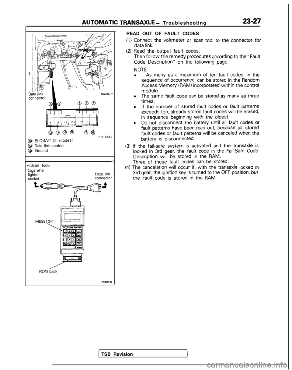
READ OUT OF FAULT CODES
(1)
Connect
the
voltmeter or scan tool
to the
connector
for data
link.
ItI ITi i i I_ . . c - 7 IIIL:‘!‘/‘!’ ‘j’:‘J
6666S@16R13388,: ELC-4PJT 12 modes1
@: Data link control
@: Ground
(2) Read
the
output fault
codes. Then
follow the remedy
procedures according to the
“Fault
Code Description”
on the following
page.
NOTE
l As many
as a maximum
of ten fault
codes, in the
sequence
of
occurrence,
can be stored
in the
Random Access
Memory (RAM) incorporated
within the
control
module.
l
The same
fault
code can be stored
as many
as three
times.
l
If the number
of stored
fault
codes or
fault
patterns
exceeds
ten,
already
stored
fault
codes
will be erased,
in
sequence
beginning
with the
oldest.
lDo
not
disconnect the
battery
until all fault
codes or
fault
patterns
have
been read out, because al! stored
fault
codes
or fault
patterns
will
be canceled when
the
battery is
disconnected.
~ ~~
(3)
If the
fail-safe
system is activated
and the
transaxle
is
locked in 3rd gear, the fault
code in the
Fail-Safe Code Description
will be stored
in the
RAM.
Three of these fault
codes can be stored.. ,.
Cigarette
lighter
socket
1
(4) The cancelation
will
occur if, with the
transaxle
locked rn 3rd
gear, the ignition
key is turned
to
the
OFF position,
but
Data link
connector the
fault code is stored
in the
RAM.
MB991 341
\
ROM back
16PO151
TSB Revision
Page 742 of 1273
23-36AUTOMATIC TRANSAXLE
- Troubleshooting
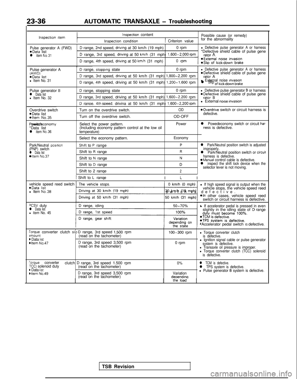
Inspectron ItemInspection content
Inspectron condrtion
Possible cause (or remedy)
1 Criterion valuefor the abnormality
Pulse generator A (FWD)D range, 2nd speed, drivrng at 30 km/h (19 mph)
0 rpml Defective pulse generator A or harness*Data
list *Defective shield cable of pulse gene
l item No.31D range, 3rd speed, drivrng at 50 km/h (31 mph) 1.600-2.000
rpmrafnr A
D range, 4th speed, driving at 50 km/h (31 mph)n
Pulse generator AW’J’JD) *Data
lrstl Item No. 31
D range, stopprng state 0 rpml Defective pulse generator A or harness *Defective
shield cable of pulse gene
D range, 3rd speed, drivrng at 50 km/h (31 mph) 1.800-2.200
rpmrator A
D range, 4th speed, driving at 50 km/h (31 mph) 1.200-1.600
rpml External noise rnvasronl Slip of kickdown brake
Pulse generator Bl Data listl Item No. 32
D range, stopping state 0 rpml Defective pulse generator B or harness
D range, 3rd speed, driving at 50 km/h (31 mph) 1.600-2.200
rpm *Defective
shield cable of pulse generator B
D ranoe. 4th soeed. drivina at 50 km/h (31 mph) 1.600-2.200
mml External noise invasron
Overdrive switch *Data
list
*Item No.35
Turn on the overdrive switch.
Turn off the overdrive switch.OD
OD-OFF
moverdrive switch or circuit harness isdefective. Power/economy switch
*Data list
l item No.36
Select the power pattern.
(Including economy pattern control at the low oil
temperature) Power
l Powedeconomy switch or circuit har-ness is defective.
Park/Neutral posrtion
(PNP) switch
l Data list*Item No.37
Select the economy pattern.
Shaft to P range
Shift to
R range
Shift to
N range
Shift to
D range
Shift to 2 ranqe
Economy
Pl Park/Neutral position switch is adjusted
improperly.
Rl Park/Neutral position switch or circuil
Nharness is defective.aManual control cable is defective.Dl inspect the shift lock device when theselector lever is not moving.2
1 Shift to L ranqe
I L I
vehicle speed reed switch *Data
lrstl Item No.38
0 km/h (0 mph)
-1
l If high speed signal is output when thevehicle stops, the vehicle speed reed
switch is defective
.
*In other cases, vehicle speed reed
switch or circuit harness is defective.
=CSV dutyl Data listl item No. 45
l If accelerator pedal is pressed in evenslightly in the idling state ofD range
*Accelerator pedal switch IS defective.
rorque converter clutch slrp D range, 3rd speed 1,500 rpmamount(read on the tachometer)m Data listmltem No.47D range, 3rd speed 3,500 rpm
(read on the tachometer) 100-300
rpm
0 rpm
l Torque converter clutch
is defective.
l Ignition signal cable or pulse generatorsystem is defective.l Transaxle oil pressure is improper.l Torque converter clutch (TCC) solenoid
is defective.
rorque converterclutch D range, 3rd speed 1.500 rpm0%l TCM is defective.TCC) solenoid duty(read on the tachometer)) Data listl TPS system is defective.
Dltem No.49D range, 3rd speed 3,500 rpmVariationl Pulse generator B system is defective.
(read on the tachometer)deoendina
TSB Revision
Page 766 of 1273
23-60AUTOMATIC TRANSAXLE - Troubleshooting
CIRCUIT DIAGRAM
cl989 models>
IGNITION
- ‘\- ‘\I-/.d2 -s/R‘*A-432.‘Da-2‘-- RD* l ND N
\$\I \I $6 >’ pg $5\I
- I 1:29‘ki 62 7 3'11
AJ5gp&%dII -IIIIIII1IIIIIIIIIIIIIIIIIIIIIIIIII-*-:
;2
III
:
R fiKJ
Ill,14(B'
1I10RI
1' 2i
B1I
Y:( 6
12(YB)114(YB'
:( 6(YR):( 5(YR;1I
0 ,16(BY)I
:( 7By @
; x15
(RL)IRL @(BW)BW @(Y)Y,"I2@I I1I\ II;;; 8
L
I--+
P
-@
@-
-@-
(RG)
:: 1I(GL)
(RG) @
I
(GR) '
(GL) a
(GR)0
&iL__-..___-------------------------~~---------------$5 ‘r-----_______________510;gyg;NATIONA-092
is
@jJA2,\
rBY43
2Et?
CL7
tBACK-UP LIGHT
STARTER
MOTOR
:X35-AC-H0707-NY
1 TSB RevisionI