Page 543 of 1273

AUTO-CRUISE CONTROL SYSTEM - Setice Adiustment Procedures13-401
16AO192
--
Ib/-
SJy-
iii
3 1
24
J
14LO142
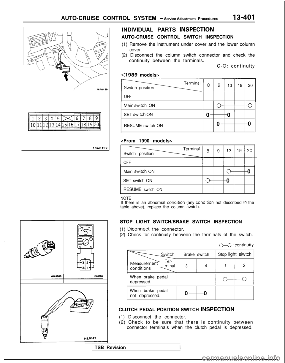
INDIVIDUAL PARTS INSPEtiTION
AUTO-CRUISE CONTROL SWITCH INSPECTION
(1) Remove the instrument under cover and the lower column cover.
(2) Disconnect the column switch connector and check the
continuity between the terminals.
C-O: continuity
<1989 models>
13 19 20
OFF Maln
switch
ON
O/I0IIIISET swttch
ON
RESUME switch ON 0 0
0 0
Switch position
OFF
Main switch
ON
SET switch ON
RESUME switch ON
00
00
NOTEIf there is an abnormal condition
(any condltlon
not described In the
table above), replace the column switch.
STOP LIGHT SWITCH/BRAKE SWITCH INSPECTION
(1)
Diconnect the connector.
(2) Check for continuity between the terminals of the switch.
M :continuity
Brake switch Stop light siwtch
341 1 2
I----II I
When brake pedal
depressed.
/b-t-4
When brake pedal
not depressed.0 0
CLUTCH PEDAL POSITION SWITCH INSPECTION (1) Disconnect the connector.
(2) Check to be sure that there is continuity between connector terminals when the clutch pedal is depressed.
1 TSB Revision
Page 547 of 1273

AUTO-CRUISE CONTROL SYSTEM - Sewice Adjustment Procedures
ECU connector terminals
19171513ll><7531
2018161412 101 98642
16A1060
ELECTRONIC CONTROL UNIT (ECU) SIGNAL CIRCUIT
CHECK
Disconnect the connector of the ECU, and then check at the
body side wiring harness according to the chart below.
IG SW: Ignition switch
MAIN SW: Main switch
OD SMI: Overdrive switch
Termi-~ Connection or mea-
nal
~
sured part Measure-
Tester con-
ment item nection
Check conditions
Standard
I-
I-
1 ~
Actuator (motor) Resistance1 - “‘2Actuator selector Approx. 120
(Fully closed position)
1
2
3I Stop light switchVoltage3-Ground ~
IG S/W ON, Main SW O
N
Battery positive
~
(for auto-cruise ~
control cancellation)
j )
i (Don’t press brake pedal.)j voltage
and actuator (clutch)I Press brake pedal after checkingBattery positive
5 1 Power supply (MAIN)
/ above.voltage -0V
Voltage5-Ground
1 IG S/W
ON, Main S/W ONBattery positive
voltage
6None-i -i-
7 1
Power supply (IGz)Voltag
e
7-GroundIG SfW O
N
Battery positive
voltage
8*z ~
On-board diagnostic--i- -
TSB Revision
9Accelerator pedal Voltageg-GroundIG SW O
N
Battery positive
switch
(Accelerator pedal free)voltage
1 Press accelerator pedal after/ Battery positive
II checking above.[voltage -0V
IO I Vehicle speed sensor
Voltage1 O-Ground’ W
ith the ignition key at the ON
’ ~
4 voltage
position, slowly turn the speedom- changes/
ca-
eter cable. ble
rotation
11SET switch
Continuity1 l-Ground ’ SET switch ON (Press) Continuity
SET switch OFF (Release) No continuity
12OD switch
13RESUME switch 1
Voltage
Continuity
12-GroundIG SNV ON OD SW ON position
Battery positive
voltage
OD
SW OFF position ~
OV
13-Ground ~
RESUME switch ON (Turn) Continuity
; RESUME switch OFF (Release)
No continuity
14’2 ~
4 A/T control module( -/- I- !
-
I/15 1 Stop light switch load
~
Voltage15-Ground’ Press the brake pedal.Battery positiveside/voltage
16 j Ground
Continuity1 16-GroundAt all times ~
Continuity
Page 548 of 1273

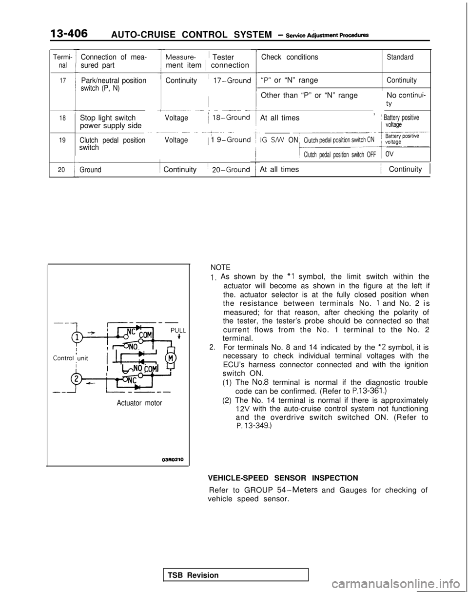
13-406AUTO-CRUISE CONTROL SYSTEM - Service A&tment ~mcec~ure~
Termi-
nal
17
18
19
20
l-
it
L
Connection of mea-
sured part Park/neutral position
switch (P, N)
T
f
+
Stop light switch
power supply side
Continuity ~
17-Ground
1
.~.~.~ ~.-. _ - ~~- -~/Voltage)
18-Ground
~~
____~ _~ ~.. ----+--.. .-~
Clutch pedal position
Voltage1 1 g-Groundswitch
Measure-1
Tester
ment item 1
connection
Ground
1 ~
Continuity ~
20-Ground
-Conrroljunitj I! @jIII LNOtOMl ‘-r’
+-j-
--J--L--
Actuator motor
03R0210
Check conditionsStandard
“P” or “N” rangeContinuity
Other than “P” or “N” range
,No continui-
v
At all timesj Battery positive
IG S/W
ON
Clutch pedal position switch OFF
At all times/ Continuity 1
NOTE
1. As shown by the “1 symbol, the limit switch within the
actuator will become as shown in the figure at the left if
the. actuator selector is at the fully closed position when
the resistance between terminals No.
1 and No. 2 i
s
measured; for that reason, after checking the polarity of
the tester, the tester’s probe should be connected so that
current flows from the No. 1 terminal to the No. 2
terminal.
2.For terminals No. 8 and 14 indicated by the “2
symbol, it is
necessary to check individual terminal voltages with the
ECU’s harness connector connected and with the ignition
switch ON.
(1) The
No.8 terminal is normal if the diagnostic trouble
code can be confirmed. (Refer to
P.13-361.)
(2) The No. 14 terminal is normal if there is approximately
12V with the auto-cruise control system not functioning
and the overdrive switch switched ON. (Refer to
P. 13-349.)
VEHICLE-SPEED SENSOR INSPECTION
Refer to GROUP
54-Meters and Gauges for checking of
vehicle speed sensor.
TSB Revision
Page 550 of 1273
Page 551 of 1273
Page 597 of 1273
INTAKE AND EXHAUST - Air Cleaner15-11
4 'NSPECT'oN
Ml5iCA95
lCheck the air cleaner body, cover or packing for deforma-
1
tion, corrosion or damage.
l Check the air duct for damage.
lCheck the air cleaner element for clogging, contamination
or damage. If element is slightly clogged, remove dust by blowing air
from inside of element.
VOLUME AIR FLOW SENSOR CHECK For inspection of volume air flow sensor, refer to GROUP
13-Volume Air Flow Sensor Check.
TSB Revision
I
Page 598 of 1273
15-12INTAKE AND EXHAUST - Charge Air Cooler
CHARGE AIR COOLER
REMOVAL AND INSTALLATION
A
12-15 Nm&-2-s--
TX.<.\-@
\\’ 19-11 ft.lbs.,_
12-15 Nm
9-11 ftlbs.
12-15-Nm9-l 1 ft.lbs.
05A0191
Removal steps
1. Radiator grille (Refer to GROUP 51 -FrontGrille.) -+e *+2. Front combination light (Refer to GROUP
54-Headlight.)
3. Headliaht
4. Front bumper face coupling clip
5. Air intake hose
6. Air cleaner (Refer to
P.15-9.)7. Air by-pass hose
8. Vacuum hose 9. Air hose A
10. Power relay assembly (for A/C)11. Air pipe A12. Air hose B13. Air pipe B14. Turbocharger by-pass valve
15. Gasket
16. Air hose Cl + 17. Charge air cooler
MXiTA-
TSB Revision
Page 624 of 1273
17-4EMISSION CONTROL SYSTEMS - Vacuum Hoses
VACUUM HOSES
VACUUM HOSES ROUTING
M17.M-
Evaporative
emission cani*--
Evaporative emission
purge solenoid
Throttle body
G: Green Thermal vacuum valve
\Y : Yellow
L : Light blue
R: Red
B : Black EGR’ valveFRONT
Fuel pressure
regulator
6EM0189
Evaporative Evaporative emission
emission canister
,I purge solenoid
Thr ot t IihR
Y
G: Green
Y:Yellow
L : Light blue
R: Red
B : Black
EGR \alveFRGT
6EM0190
TSB Revision
EGRsolenoid
Fuel pressure
regulator