1989 MITSUBISHI GALANT light
[x] Cancel search: lightPage 445 of 1273
r
FUEL SYSTEM
of
MFI Components13-303
INSPECTION
Using Scan tool
Function Item No.
Data reading 44
Data displayInspection conditionsEngine condition Standard value
Ignition
advance
. Engine: warm
. Timing light: set750 rpm (idling)5-15” BTDC
(Use the timing light to
check the actual ignition 2,000 rpm32 - 4 1 “BTDCtiming.)
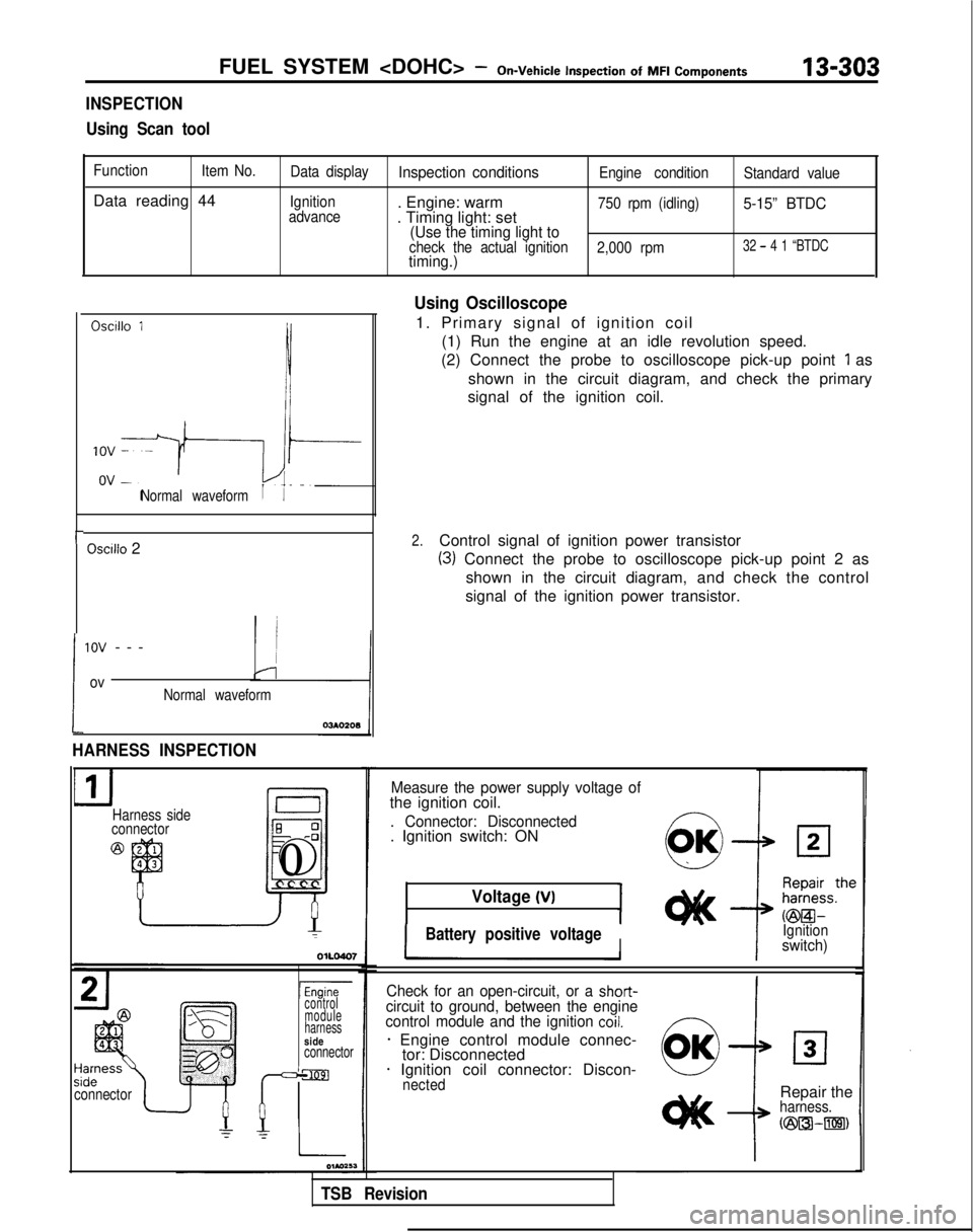
Oscillo 1
Normal waveform
Oscilio 2
!
1ov --
-
ovNormal waveform
HARNESS INSPECTION
Harness side
connectorE 0-0
J
El0
connectorI
lEnginecontrol
module
harness
sideconnector
Using Oscilloscope
1. Primary signal of ignition coil
(1) Run the engine at an idle revolution speed.
(2) Connect the probe to oscilloscope pick-up point
1 as
shown in the circuit diagram, and check the primary
signal of the ignition coil.
2.Control signal of ignition power transistor
(3) Connect the probe to oscilloscope pick-up point 2 as
shown in the circuit diagram, and check the control
signal of the ignition power transistor.
Measure the power supply voltage ofthe ignition coil.
. Connector: Disconnected. Ignition switch: ON
Voltage (VI
IBattery positive voltageIIIgnitionswitch)
Check for an open-circuit, or a
short-circuit to ground, between the engine
control module and the ignition coil.
* Engine control module connec- tor: Disconnected
* Ignition coil connector: Discon-nected
i
Repair theharness.
N23l3k-m)
TSB Revision
Page 458 of 1273
13-316FUEL SYSTEM
Inspection
of
MFI
Components
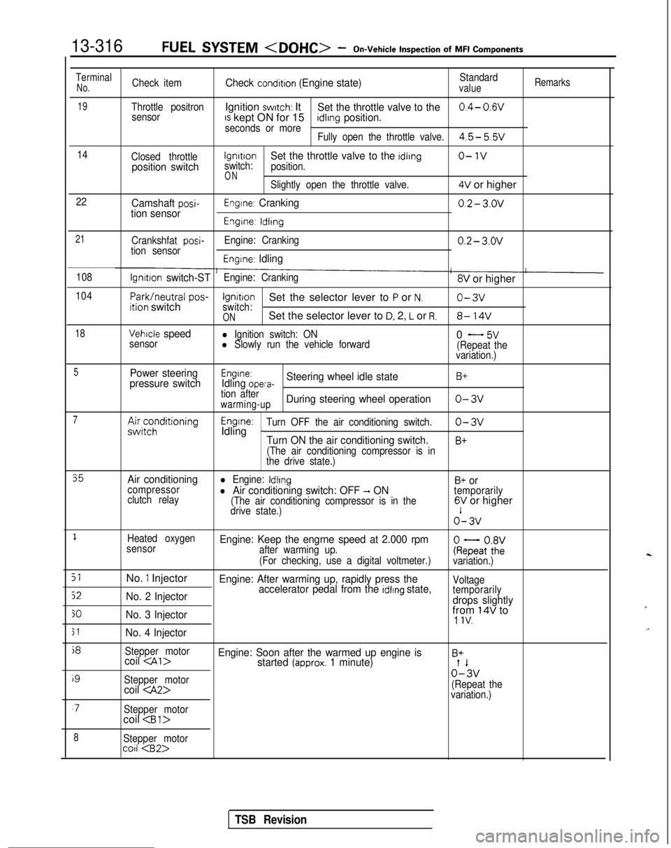
TerminalNo.Check itemCheck condition (Engine state)Standardvalue
Remarks
19Throttle positronIgnition switch: ItSet the throttle valve to the0.4- 0.wsensorIS kept ON for 15seconds or moreidlrng position.
Fully open the throttle valve.4.5- 5.5v
14
Closed throttlelgnrtrono-1vposition switchswitch:Set the throttle valve to the idling
position.
ONSlightly open the throttle valve.4V or higher
22Camshaft posi-tion sensorEngine: Cranking0.2- 3.ov
Engine: ldlrng
21
Crankshfat posi-tion sensor Engine: Cranking0.2- 3.ov
Engine: Idling
108lgnrtion switch-STEngine: Cranking8V or higher
104
Park/neutral
pos-ition switchIgnitionSet the selector lever to P or N.o-3vswitch:ONSet the selector lever to D, 2, L or R.8- 14V
18Vehicle speedl Ignition switch: ON
sensorl Slowly run the vehicle forward0 - 5v(Repeat the
variation.)
5Power steering
pressure switchEngine:Idling opera-Steering wheel idle stateB+
tion afterwarming-upDuring steering wheel operationo-3v
7A&;;;ditioningEngine:Idling _Turn OFF the air conditioning switch.o-3v
Turn ON the air conditioning switch.B+
(The air conditioning compressor is in
the drive state.)
35Air conditioningl Engine: IdlingB+ orcompressor
clutch relayl Air conditioning switch: OFF -, ON(The air conditioning compressor is in the
temporarily
drive state.)6V or higher o’-
3v
1Heated oxygen
sensorEngine: Keep the engrne speed at 2.000 rpmafter warming up.
(For checking, use a digital voltmeter.)ke;atoZivariation.)
51No. 1 InjectorEngine: After warming up, rapidly press the
52No. 2 Injector accelerator pedal from the idlrng state,Voltage
temporarily
drops slightly
30No. 3 Injectorfrom 14V to1 IV.
51No. 4 Injector
j8
Stepper motorcoil
i9
Stepper motor0%
coil
variation.)
‘7Stepper motorcoil
8Stepper motorco11
TSB Revision
Page 459 of 1273
FUEL SYSTEM
Inspection
of MFI
Components13-317
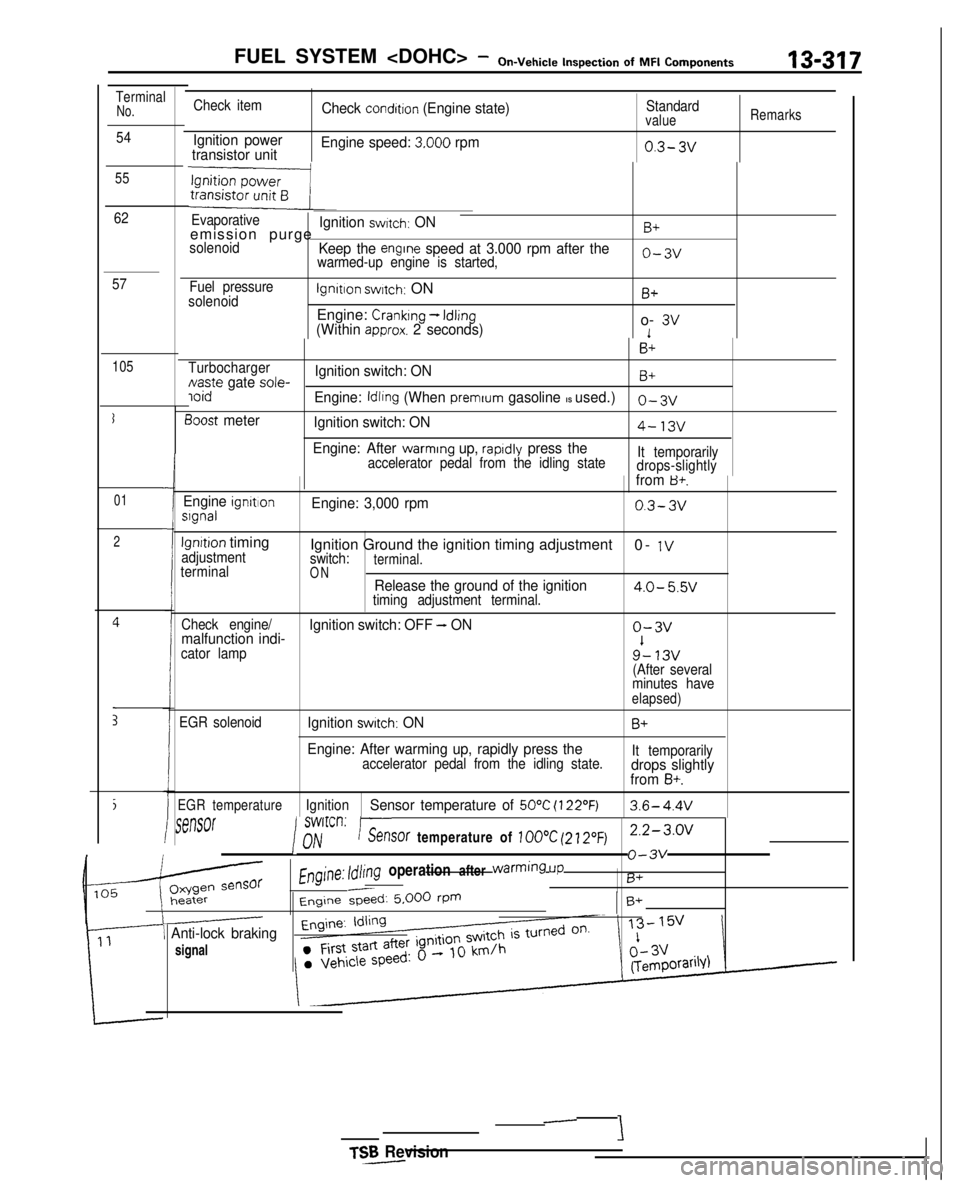
TerminalNo.
54
55
62
57
105
I
01
2
i
E
Check item
Ignition power
transistor unit Check
condition (Engine state)
Engine speed:
3.000 rpm
Standardvalue
0.3- 3v
Remarks
Evaporativeemission purgeIgnition switch: ONB+
solenoidKeep the engrne speed at 3.000 rpm after thewarmed-up engine is started,o-3v
Fuel pressure
solenoidlgnltlon switch: ON
Engine:
Cranking - Idling(Within approx. 2 seconds)
B+
o- 3v1
B+
TurbochargerNaste gate sole-Ignition switch: ONB+ ioid
Engine: Idling (When premrum gasoline IS used.)0-3~
3oost meter
Ignition switch: ON4-13v
Engine: After warming up, rapldly press theaccelerator pedal from the idling state It temporarily
drops-slightlyIfrom B+.
Engine ignrtlonslgnalEngine: 3,000 rpm0.3-3v
lgnrtion timingadjustment
terminalIgnition Ground the ignition timing adjustment 0- 1Vswitch:terminal.ONRelease the ground of the ignition4.0- 5.5vtiming adjustment terminal.
Check engine/
malfunction indi- Ignition switch: OFF - ONo-3v
cator lamp9’- 13v(After several
minutes have
elapsed)
EGR solenoidIgnition switch: ONB+
Engine: After warming up, rapidly press theaccelerator pedal from the idling state. It temporarilydrops slightly
from B+.
EGR temperatureIgnitionSensor temperature of 50°C (122’F)3.6- 4.4V
rSt?MX
I
swlrcrl:nhir--.%?nY/V-_. ..sof temperature of 100°C (21.20~)2.2-3.0~
Engine: Idling operation after warming
UP
o-3v
B+
Engine &ed: 5.000 rPmB+
\ Anti-lock braking
signal
TSR Revision-
-
‘i
Page 461 of 1273
FUEL SYSTEM
Fuel tank pressure
control valve
Rubb& hose
side
003041
03FOO1
INSPECTIONMl3GCAIl
l Check the hoses and the pipes for crack or damage.
lCheck the fuel tank filler tube cap for malfunction.
lCheck the fuel tank for deformation, corrosion or crack.
l Check the fuel tank for dust
Qr foreign material.
NOTE
If the inside of the fuel tank is to be cleaned, use any one
of the following:
(1) Kerosene
(2) Trichloroethylene
(3) A neutral emulsion type detergent
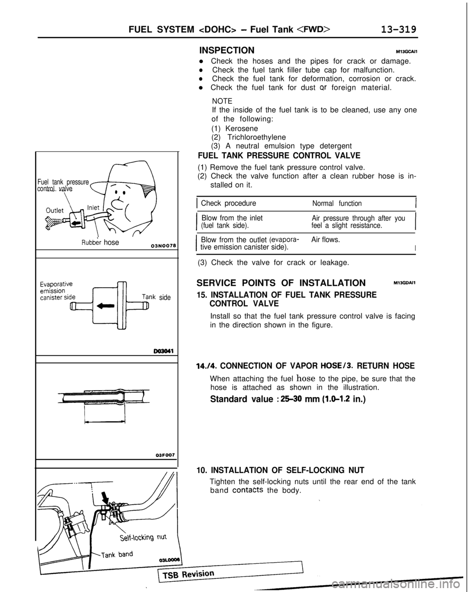
FUEL TANK PRESSURE CONTROL VALVE
(1) Remove the fuel tank pressure control valve.
(2) Check the valve function after a clean rubber hose is in-
stalled on it.
1 Check procedureNormal function
I
Blow from the inletAir pressure through after you
(fuel tank side). feel a slight resistance.
I
I
Blow from the outlet (evapora-Air flows.
tive emission canister side).
I
(3) Check the valve for crack or leakage.
SERVICE POINTS OF INSTALLATION
MlJGDAIl
15. INSTALLATION OF FUEL TANK PRESSURE CONTROL VALVE
Install so that the fuel tank pressure control valve is facing
in the direction shown in the figure.
14./4. CONNECTION OF VAPOR HOSE/3. RETURN HOSE
When attaching the fuel hose to the pipe, be sure that the
hose is attached as shown in the illustration.
Standard value : 25-30 mm (1.0-1.2 in.)
10. INSTALLATION OF SELF-LOCKING NUT
Tighten the self-locking nuts until the rear end of the tankband
contacts the body.
Page 474 of 1273
13-332
AUTO-CRUISE CONTROL SYSTEM - Specifications
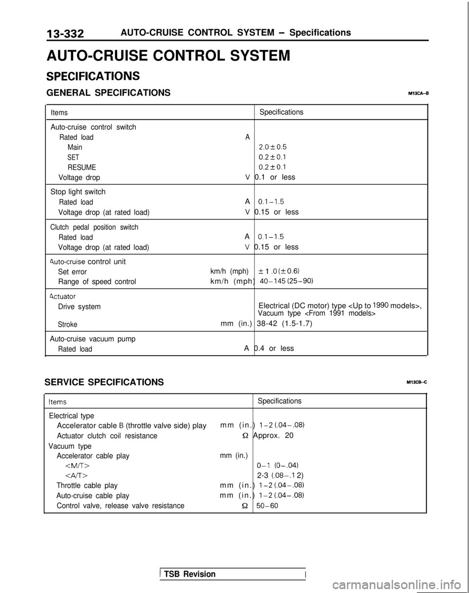
AUTO-CRUISE CONTROL SYSTEM
SPECIFICATIONS
GENERAL SPECIFICATIONSM13CA--B
Items
Auto-cruise control switch
Rated load Main
SET
RESUME
Voltage drop
Stop light switch
Rated load
Voltage drop (at rated load)
Clutch pedal position switch
Rated load
Voltage drop (at rated load)
4uto-cruise control unit
Set errorRange of speed control
4ctuator
Drive system
Stroke
Auto-cruise vacuum pump
Rated load
Specifications
A
2.0f0.5
0.2fO.l 0.2t-0.1
V 0.1 or less
A
0.1-1.5
V 0.15 or less
A
0.1-1.5
V 0.15 or less
km/h (mph)IL 1 .O (kO.6)
km/h (mph) 40-145
(25-90)
Electrical (DC motor) type
mm (in.) 38-42 (1.5-1.7)
A 0.4 or less
SERVICE SPECIFICATIONS
Ml3CB-.C
ItemsSpecifications
Electrical type
Accelerator cable B (throttle valve side) play mm (in.) l-2 (.04-.08)
Actuator clutch coil resistanceQ Approx. 20
Vacuum type
Accelerator cable play mm (in.)
Gv-r~2-3 (.08-.I 2)
Throttle cable playmm (in.) l-2 (.04-.08)
Auto-cruise cable playmm (in.) l-2
(.04-.08)
Control valve, release valve resistance52 50-60
1 TSB RevisionI
Page 478 of 1273
13-336AUTO-CRUISE CONTROL SYSTEM - Troubleshooting
Probable cause1 Check chart No.1 Remedy
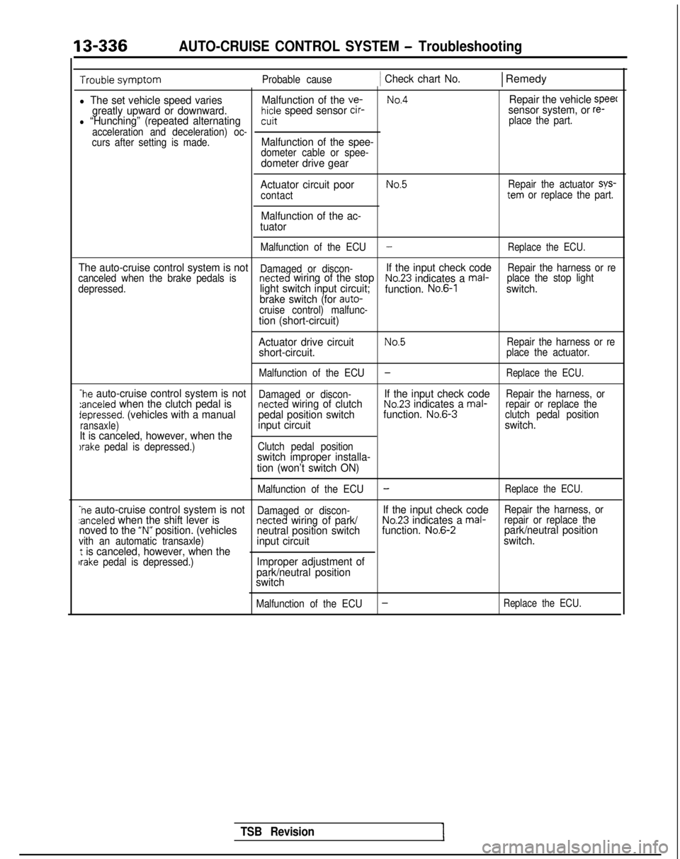
l The set vehicle speed variesMalfunction of the ve-No.4Repair the vehicle speec
greatly upward or downward.hicle speed sensor cir-sensor system, or re-l “Hunching” (repeated alternatingcuit place the part.
acceleration and deceleration) oc-
curs after setting is made.
Malfunction of the spee-dometer cable or spee-dometer drive gear
Actuator circuit poor
contact
Malfunction of the ac-
tuator
No.5Repair the actuator sys-tern or replace the part.
Malfunction of the ECU
-Replace the ECU.
The auto-cruise control system is notDamaged or discon-If the input check codeRepair the harness or re
canceled when the brake pedals isnetted wiring of the stopNo.23 indicates a mal- place the stop light
depressed.light switch input circuit; function. No.6-1switch.
brake switch (for auto-
cruise control) malfunc-
tion (short-circuit)
Actuator drive circuit
No.5Repair the harness or reshort-circuit.place the actuator.
Malfunction of the ECU
-Replace the ECU.
-he auto-cruise control system is notDamaged or discon-If the input check codeRepair the harness, or:anceled when the clutch pedal isnetted wiring of clutchNo.23 indicates a mal- repair or replace thedepressed. (vehicles with a manual pedal position switchfunction. No.6-3
clutch pedal position
ransaxle)input circuit switch.
It is canceled, however, when the
)rake pedal is depressed.) Clutch pedal positionswitch improper installa-
tion (won’t switch ON)
Malfunction of the ECU-Replace the ECU.
-he auto-cruise control system is notDamaged or discon-If the input check codeRepair the harness, orzanceled when the shift lever isnetted wiring of park/No.23 indicates a mal- repair or replace thenoved to the “N” position. (vehicles
neutral position switch function. No.6-2park/neutral positionvith an automatic transaxle)input circuit switch.t is canceled, however, when theIrake pedal is depressed.)Improper adjustment of
park/neutral position
switch
Malfunction of the ECU-Replace the ECU.
TSB Revision
Page 479 of 1273
AUTO-CRUISE CONTROL SYSTEM - Troubleshooting
13-337
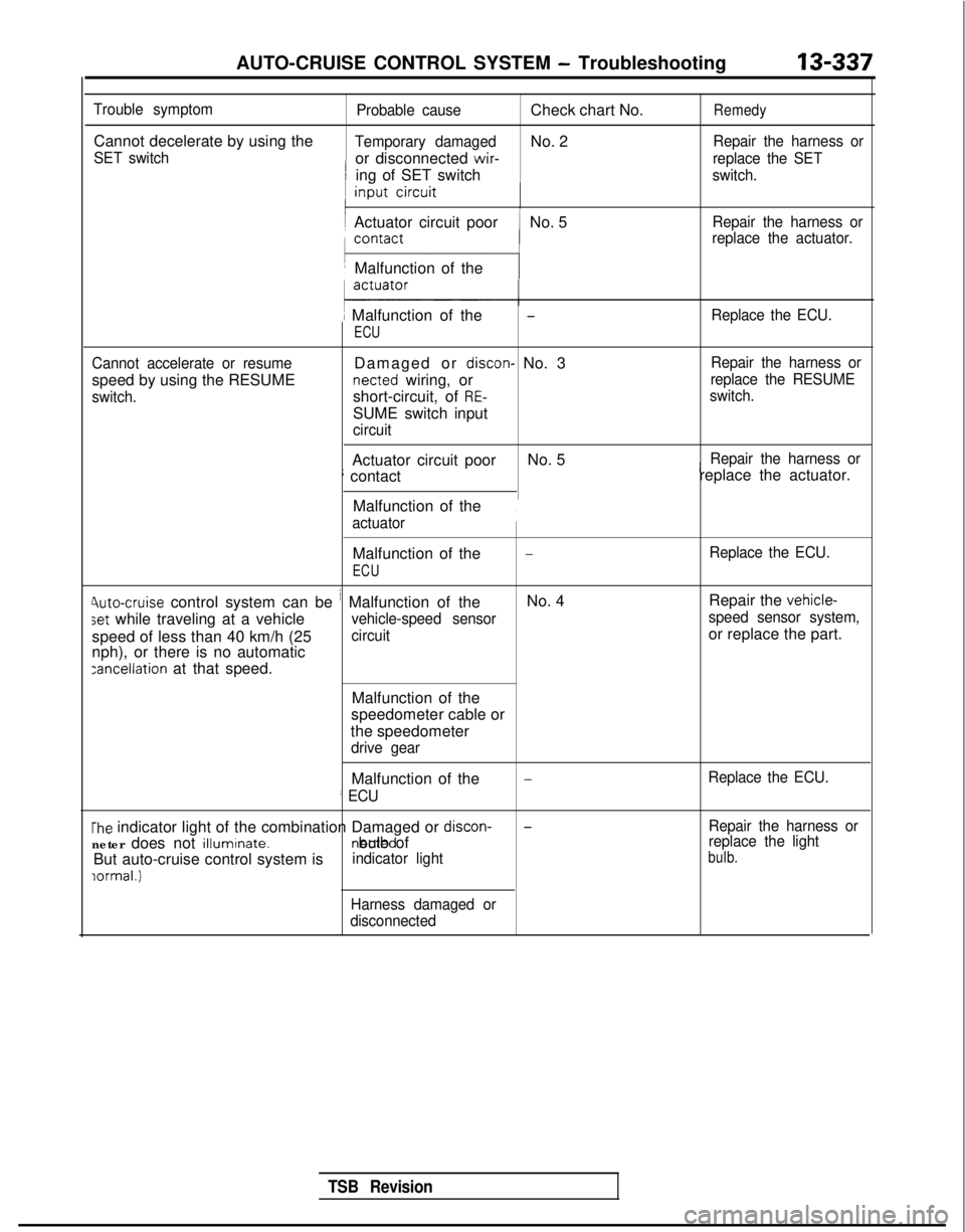
Trouble symptom
Cannot decelerate by using the
SET switch
Probable cause
Check chart No.Remedy
Temporary damagedNo. 2Repair the harness or
or disconnected wir-
replace the SET
ing of SET switchswitch.
Actuator circuit poorNo. 5Repair the harness or
replace the actuator.
Malfunction of the
1 Malfunction of the
ECU
-Replace the ECU.
Cannot accelerate or resume
speed by using the RESUME
switch.
Damaged or discon- No. 3 netted
wiring, or
short-circuit, of
RE-
SUME switch input
circuit Repair the harness or
replace the RESUME
switch.
Actuator circuit poor No. 5iRepair the harness or
; contact replace the actuator.
Malfunction of the
actuator
,
Malfunction of the-Replace the ECU.
ECU
Jute-cruise control system can be i Malfunction of the No. 4
Repair the vehicle-
set while traveling at a vehiclevehicle-speed sensor speed sensor system,
speed of less than 40 km/h (25circuitor replace the part.
nph), or there is no automatic
zancellation at that speed.
Malfunction of the
speedometer cable or
the speedometer
drive gear
Malfunction of the
’ ECU
-Replace the ECU.
The indicator light of the combination Damaged or discon-
neter does not illuminate. netted bulb of
But auto-cruise control system isindicator light
lormal.1
-Repair the harness or
replace the light
bulb.
Harness damaged or
disconnected
TSB Revision
Page 486 of 1273
13-344AUTO-CRUISE CONTROL SYSTEM - Troubleshooting
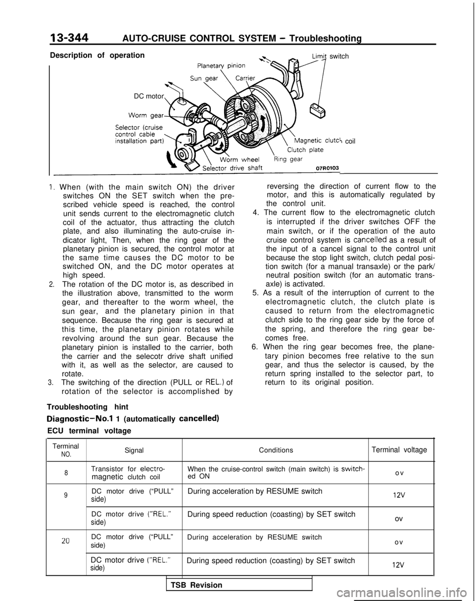
Description of operation
* -LimA switch
DC motor
7 coil
-
1. When (with the main switch ON) the driver switches ON the SET switch when the pre-
scribed vehicle speed is reached, the control
unit sends current to the electromagnetic clutch
coil of the actuator, thus attracting the clutch plate, and also illuminating the auto-cruise in-
dicator light, Then, when the ring gear of the planetary pinion is secured, the control motor at
the same time causes the DC motor to be
switched ON, and the DC motor operates at high speed.
2.The rotation of the DC motor is, as described in
the illustration above, transmitted to the worm
gear, and thereafter to the worm wheel, the
sun gear, and the planetary pinion in that
sequence. Because the ring gear is secured at
this time, the planetary pinion rotates while revolving around the sun gear. Because the
planetary pinion is installed to the carrier, both
the carrier and the selecotr drive shaft unified
with it, as well as the selector, are caused to rotate.
3.The switching of the direction (PULL or REL.) of
rotation of the selector is accomplished by reversing the direction of current flow to the
motor, and this is automatically regulated by
the control unit.
4. The current flow to the electromagnetic clutch
is interrupted if the driver switches OFF the
main switch, or if the operation of the auto
cruise control system is
cancelled as a result of
the input of a cancel signal to the control unit because the stop light switch, clutch pedal posi-
tion switch (for a manual transaxle) or the park/ neutral position switch (for an automatic trans-
axle) is activated.
5. As a result of the interruption of current to the
electromagnetic clutch, the clutch plate is
caused to return from the electromagnetic
clutch side to the ring gear side by the force of
the spring, and therefore the ring gear be-
comes free.
6. When the ring gear becomes free, the plane-
tary pinion becomes free relative to the sungear, and thus the selector is caused, by the
return spring installed to the selector part, to
return to its original position.
Troubleshooting hint
Diagnostic-No.1 1 (automatically cancelled)
ECU terminal voltage
Terminal
NO.Signal ConditionsTerminal voltage
8Transistor for electro-When the cruise-control switch (main switch) is switch-
magnetic clutch coiled ON o
v
9DC motor drive (“PULL”
During acceleration by RESUME switch
side) 12v
DC motor drive (“REL.”
During speed reduction (coasting) by SET switch
side)ov
20DC motor drive (“PULL” During acceleration by RESUME switch
side) o
v
DC motor drive (“REL.”
During speed reduction (coasting) by SET switch
side) 12v
TSB Revision