1989 MITSUBISHI GALANT light
[x] Cancel search: lightPage 487 of 1273
AUTO-CRUISE CONTROL SYSTEM - Troubleshooting13-345
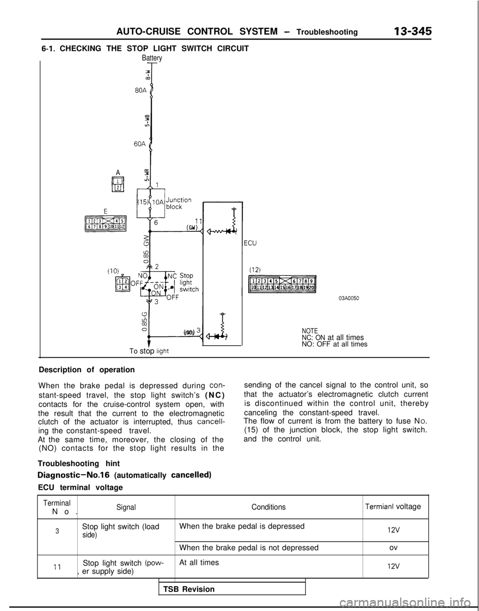
6-1. CHECKING THE STOP LIGHT SWITCH CIRCUIT
Battery
7Tco
A
9%6
I-
(GO) :
To stop light
NOTENC: ON at all timesNO: OFF at all times
Description of operation
When the brake pedal is depressed during
con-
stant-speed travel, the stop light switch’s (NC
)
contacts for the cruise-control system open, with
the result that the current to the electromagnetic
clutch of the actuator is interrupted, thus
cancell-
ing the constant-speed travel.
At the same time, moreover, the closing of the (NO) contacts for the stop light results in the
Troubleshooting hint sending of the cancel signal to the control unit, so
that the actuator’s electromagnetic clutch current is discontinued within the control unit, thereby
canceling the constant-speed travel.
The flow of current is from the battery to fuse N O.
(15) of the junction block, the stop light switch.
and the control unit.
Diagnostic-No.16 (automatically cancelled)
ECU terminal voltage
Terminal
No
.
SignalConditions
3Stop light switch (load
When the brake pedal is depressed
side)
When the brake pedal is not depressed
11Stop light switch (pow-At all times
, er supply side)
TSB Revision
Termianl voltage 12v
ov
12v
Page 493 of 1273
AUTO-CRUISE CONTROL SYSTEM - Troubleshooting
NOTE
13-351
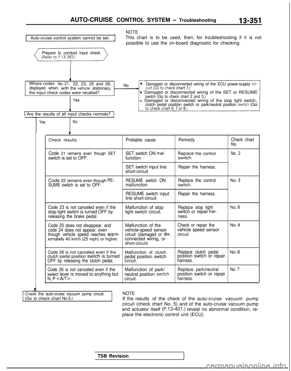
Auto-cruise control system cannot be set.
This chart is to be used, then, for troubleshooting if it is not
possible to use the on-board diagnostic for checking.
Prepare to conduct input check.
Where codesNo.21,22, 23, 25 and 26,displayed when,with the vehicle stationary,
the input check codes were recalled?Damaged or disconnected wiring of the ECU power-supply cir-
l Damaged or disconnected wiring of the SET or RESUMEswitch (Go to check chart 2 and 3.)l Damaged or disconnected wiring of the stop light switch,clutch pedal position switch or park/neutral position switch (Go
1 Are the results of all input checks normals?
YesNo
ck the auto-cruise vacuum pump circuit.1 (Go to check chart No.5.)
TSB Revision1 7
Check results
’Probable cause RemedyCheck chartNo.
Code 21 remains even though SETswitch is set to OFF. SET switch ON mal-function
SET switch input line
short-circuitF,I~JI;? the control
Repair the harness.
No. 2
Code 22 remains even though RE-SUME switch is set to OFF. RESUME switch ON
Replace the controlNo.3malfunctionswitch.
RESUME switch inputRepair the harness.line short-circuit
Code 23 is not canceled even if theMalfunction of stopReplace stop lightNo.6
stop light switch is turned OFF by light switch circuit.switch or repair har-
releasing the brake pedal.
ness.
Code 25 does not disappear, and
Malfunction of theCheck or repair theNo.4
code 24 does not appear, evenvehicle-speed sensor vehicle speed sensorthough vehicle speed reaches appro-circuit (damaged or dis-circuit.ximately 40 km/h (25 mph) or higher.connected wiring, orshort-circuit)
Code 26 is not canceled even if the Malfunction of clutch
Replace clutch pedalNo.8clutch pedal position switch is turnedpedal position switchposition switch or repairOFF by releasing the clutch pedal.
circuit.harness.
Code 26 is not canceled even if the
Malfunction of park/Replace park/neutralNo. 7
select lever is moved to anything but neutral position ,switchposition switch or repair
v. P .circuit.harness.
NOTE
If the results of the check of the auto-cruise vacuum pump
circuit (check chart No. 5) and of the auto-cruise vacuum pump
and actuator itself
(P.13-401.) reveal no abnormal condition, re-
place the electronic control unit (ECU).
Page 494 of 1273
13-352AUTO-CRUISE CONTROL SYSTEM - Troubleshooting
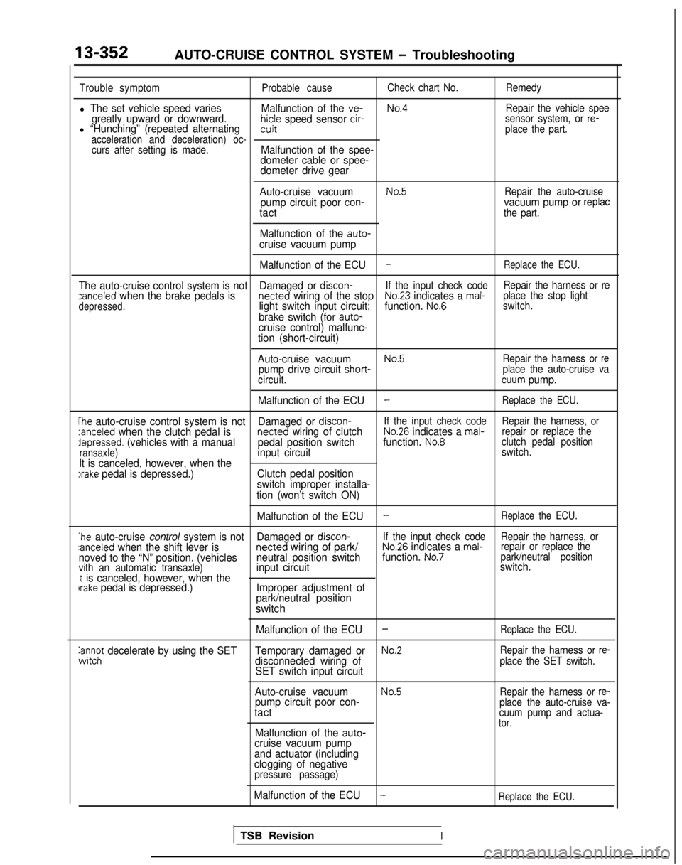
Trouble symptomProbable causeCheck chart No.
Remedy
l The set vehicle speed varies Malfunction of the ve-No.4Repair the vehicle speegreatly upward or downward.hicle speed sensor cir-l “Hunching” (repeated alternatingsensor system, or re-witplace the part.
acceleration and deceleration) oc- curs after setting is made.
Malfunction of the spee-
dometer cable or spee-
dometer drive gear
Auto-cruise vacuum
No.5Repair the auto-cruisepump circuit poor con-vacuum pump or replactactthe part.
Malfunction of the auto-cruise vacuum pump Malfunction of the ECU
-Replace the ECU.
The auto-cruise control system is not Damaged or discon-If the input check code Repair the harness or rezanceled when the brake pedals is netted wiring of the stopNo.23 indicates a mal-
depressed.light switch input circuit; function. No.6place the stop light
switch.
brake switch (for auto-cruise control) malfunc-
tion (short-circuit)
Auto-cruise vacuum
No.5Repair the harness or repump drive circuit short- place the auto-cruise va
circuit.cuum pump.
Malfunction of the ECU
-Replace the ECU.
The auto-cruise control system is not Damaged or discon-If the input check code
Repair the harness, or:anceled when the clutch pedal is netted wiring of clutchNo.26 indicates a mal-repair or replace thedepressed. (vehicles with a manual
pedal position switchfunction. No.8clutch pedal position
ransaxle)input circuitswitch.
It is canceled, however, when theIrake pedal is depressed.) Clutch pedal position
switch improper installa-
tion (won’t switch ON)
Malfunction of the ECU
-Replace the ECU.
*he auto-cruise control system is not Damaged or discon-If the input check code
Repair the harness, or:anceled when the shift lever is netted
wiring of park/No.26 indicates a mal-repair or replace the
noved to the “N” position. (vehicles neutral position switchfunction. No.7park/neutral position
vith an automatic transaxle)input circuit switch.t is canceled, however, when thebrake pedal is depressed.)
Improper adjustment of
park/neutral position
switch
Malfunction of the ECU-Replace the ECU.
anc$ decelerate by using the SET Temporary damaged orNo.2Repair the harness or re-disconnected wiring of
SET switch input circuitplace the SET switch.
Auto-cruise vacuumNo.5Repair the harness or re-pump circuit poor con-
tactplace the auto-cruise va-
cuum pump and actua-
tor.Malfunction of the auto-cruise vacuum pump
and actuator (including
clogging of negative
pressure passage)
Malfunction of the ECU-Replace the ECU.
TSB RevisionI
Page 495 of 1273
AUTO-CRUISE CONTROL SYSTEM - Troubleshooting13-353
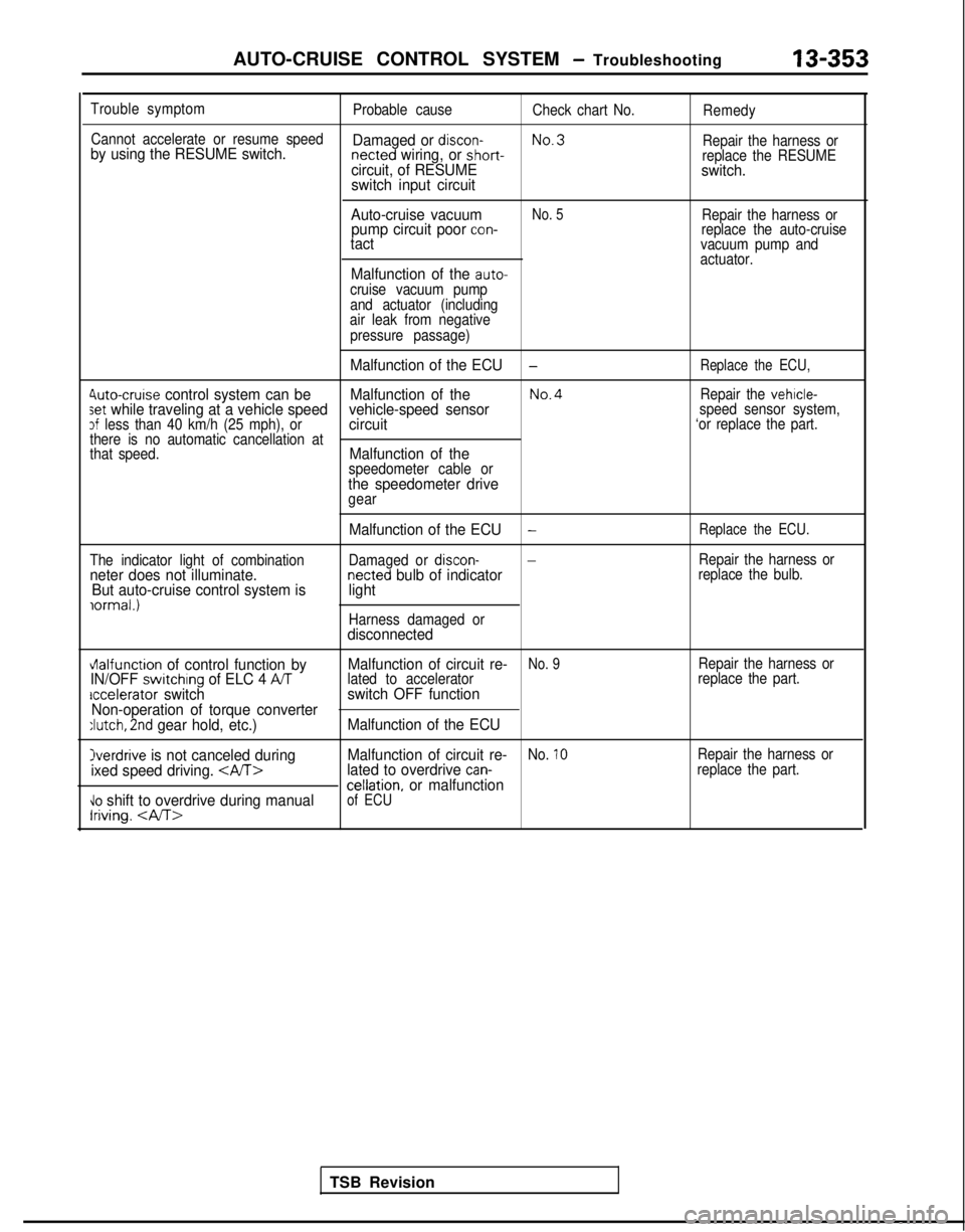
Trouble symptom
Probable causeCheck chart No.Remedy
Cannot accelerate or resume speed
No.3
by using the RESUME switch. Damaged or discon- netted wiring, or short-
Repair the harness orcircuit, of RESUMEreplace the RESUMEswitch.
switch input circuit
Auto-cruise vacuum
No. 5Repair the harness orpump circuit poor con-replace the auto-cruisetactvacuum pump and
actuator.
Malfunction of the auto-cruise vacuum pump
and actuator (including
air leak from negative
pressure passage)
Malfunction of the ECU-Replace the ECU,
4uto-cruise control system can be Malfunction of theNo.4Repair the vehicle-set while traveling at a vehicle speed vehicle-speed sensorspeed sensor system,3f less than 40 km/h (25 mph), orcircuit‘or replace the part.
there is no automatic cancellation at
that speed.
Malfunction of thespeedometer cable orthe speedometer drivegear
The indicator light of combination
neter does not illuminate. But auto-cruise control system is
iormal.)
Malfunction of the ECU-Replace the ECU.
Damaged or discon--Repair the harness ornetted bulb of indicatorreplace the bulb.light
Harness damaged ordisconnected
vlalfunction of control function by Malfunction of circuit re-No. 9Repair the harness orIN/OFF switchrng of ELC 4 ATlated to accelerator
replace the part.accelerator switchswitch OFF function
Non-operation of torque converter
:lutch, 2nd gear hold, etc.) Malfunction of the ECU
Overdrive is not canceled during Malfunction of circuit re-No. 10Repair the harness or
ixed speed driving. lated to overdrive can-replace the part.cellation, or malfunction\lo shift to overdrive during manualIriving.
of ECU
TSB Revision
Page 499 of 1273
AUTO-CRUISE CONTROL SYSTEM - Troubleshooting
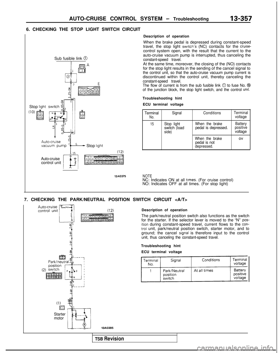
6. CHECKING THE STOP LIGHT SWITCH CIRCUIT13-357
Stop lrght
Sub fusible link @I
Stop lrght
Auto-cruisecontrol unit 13AQ375
Description of operation
When the brake pedal is depressed during constant-speed
travel, the stop light
swrtch’s (NC) contacts for the cruise-control system open, with the result that the current to the
auto-cruise vacuum pump is interrupted, thus canceling the
constant-speed travel.At the same time, moreover, the closing of the (NO) contacts
for the stop light results in the sending of the cancel signal to
the control unit, so that the auto-cruise vacuum pump current isdiscontinued within the control unit, thereby canceling theconstant-speed travel.
The flow of current is from the sub fusible link @ to fuse No. @Iof the junction block, the stop light switch, and the control unit.
Troubleshooting hint
ECU terminal voltage
TerminalSignal ConditionsTerminalNo.voltage
15Stop light
When the brake Batteryswitch (loadpedal is depressed.positive
side)voltage
When the brakeovpedal is notdepressed.
NOTENC: Indicates ON at all times. (For cruise control)
NO: Indicates OFF at all times. (For stop light)
7. CHECKING THE PARK/NEUTRAL POSITION SWITCH CIRCUIT Description of operation
The park/neutral position switch also functions as the switch
for the starter. If the selector lever is moved to the “N”
pos-ition during constant-speed travel, current flows to the con-trol unit, park/neutral position switch, starter motor, and to
ground; the cancel signal is therefore input to the controlunit, thus canceling the constant-speed travel.
Troubleshooting hint
ECU terminal voltage
(I)
ia
Starter
motor
TSB Revision
Page 503 of 1273
AUTO-CRUISE CONTROL SYSTEM - Troubleshooting13-361
Wi
thscan tool
With voltmeter
Auto-cruise control
\
Data link
connector
III
n
,
/r-I
/Ground161009
Data link
connector
TSB Revision ON-BOARD DIAGNOSTIC CHECK
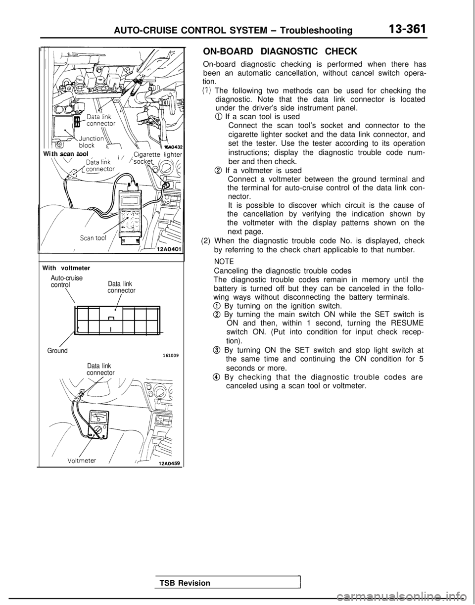
On-board diagnostic checking is performed when there has
been an automatic cancellation, without cancel switch opera-
tion.
(1) The following two methods can be used for checking the diagnostic. Note that the data link connector is locatedunder the driver’s side instrument panel.
@ If a scan tool is used
Connect the scan tool’s socket and connector to the
cigarette lighter socket and the data link connector, and
set the tester. Use the tester according to its operation
instructions; display the diagnostic trouble code num-
ber and then check.
@ If a voltmeter is used Connect a voltmeter between the ground terminal and
the terminal for auto-cruise control of the data link con-
nector.
It is possible to discover which circuit is the cause of
the cancellation by verifying the indication shown by
the voltmeter with the display patterns shown on the
next page.
(2) When the diagnostic trouble code No. is displayed, check by referring to the check chart applicable to that number.
NOTE
Canceling the diagnostic trouble codes
The diagnostic trouble codes remain in memory until the battery is turned off but they can be canceled in the follo-
wing ways without disconnecting the battery terminals.
@ By turning on the ignition switch.
@ By turning the main switch ON while the SET switch is ON and then, within 1 second, turning the RESUME
switch ON. (Put into condition for input check recep-
tion).
@ By turning ON the SET switch and stop light switch at the same time and continuing the ON condition for 5
seconds or more.
@I By checking that the diagnostic trouble codes are canceled using a scan tool or voltmeter.
Page 505 of 1273
AUTO-CRUISE CONTROL SYSTEM - Troubleshooting13-363
With scan toolri++, lighter ;
03A0258
TSB Revision
After the diagnostic trouble codes in the memory are
erased, if (when the power supply of the electronic controlunit is switched ON once again) the power supply of the
electronic control unit is normal, the on-board diagnostic
output code display will be as below, regardless of
whether the system condition is normal or not.
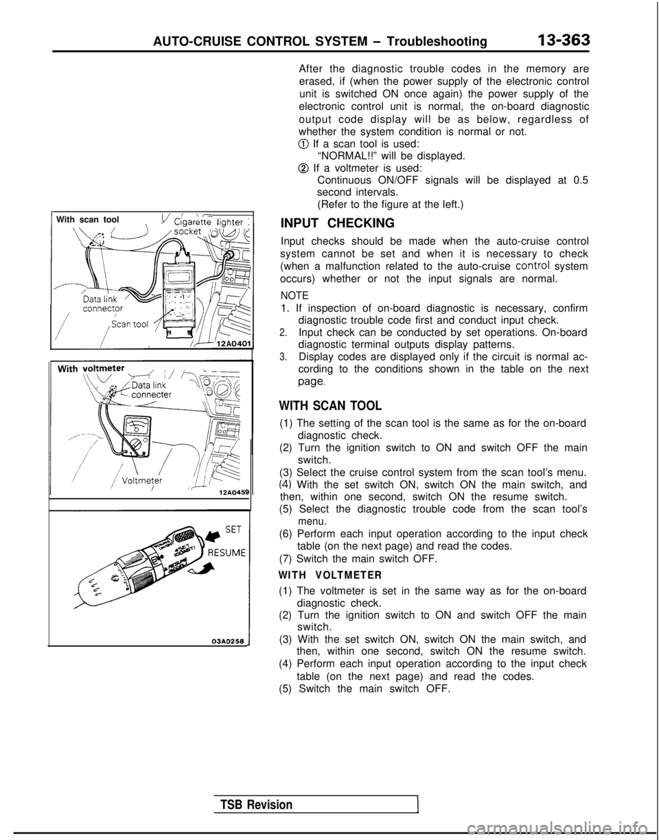
@ If a scan tool is used: “NORMAL!!” will be displayed.
@ If a voltmeter is used:Continuous ON/OFF signals will be displayed at 0.5
second intervals.
(Refer to the figure at the left.)
INPUT CHECKING
Input checks should be made when the auto-cruise control
system cannot be set and when it is necessary to check
(when a malfunction related to the auto-cruise
contra! system
occurs) whether or not the input signals are normal.
NOTE
1. If inspection of on-board diagnostic is necessary, confirm diagnostic trouble code first and conduct input check.
2.Input check can be conducted by set operations. On-board
diagnostic terminal outputs display patterns.
3.Display codes are displayed only if the circuit is normal ac-
cording to the conditions shown in the table on the next
paw
WITH SCAN TOOL
(1) The setting of the scan tool is the same as for the on-board diagnostic check.
(2) Turn the ignition switch to ON and switch OFF the main switch.
(3) Select the cruise control system from the scan tool’s menu.
(4) With the set switch ON, switch ON the main switch, and
then, within one second, switch ON the resume switch.
(5) Select the diagnostic trouble code from the scan tool’s
menu.
(6) Perform each input operation according to the input check table (on the next page) and read the codes.
(7) Switch the main switch OFF.
WITH VOLTMETER
(1) The voltmeter is set in the same way as for the on-board diagnostic check.
(2) Turn the ignition switch to ON and switch OFF the main switch.
(3) With the set switch ON, switch ON the main switch, and then, within one second, switch ON the resume switch.
(4) Perform each input operation according to the input check
table (on the next page) and read the codes.
(5) Switch the main switch OFF.
Page 506 of 1273
13-364AUTO-CRUISE CONTROL SYSTEM - Troubleshooting
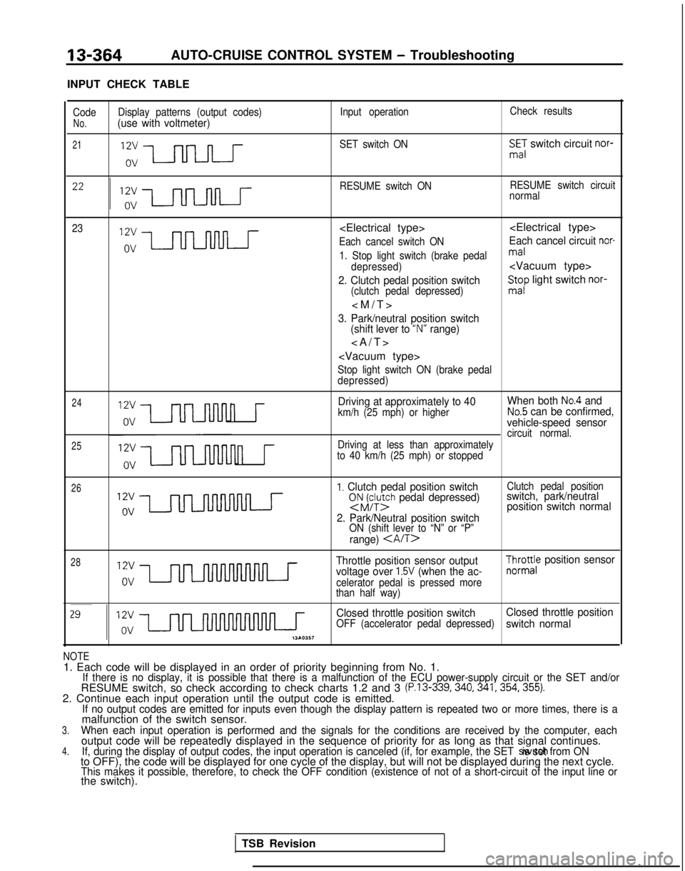
INPUT CHECK TABLE
Code Display patterns (output codes) Input operationCheck resultsNo.(use with voltmeter)
21SET switch ONSmE,: switch circuit nor-
RESUME switch ON RESUME switch circuit
normal
23
Each cancel switch ONEach cancel circuit nor-
1. Stop light switch (brake pedalmal
depressed)
2. Clutch pedal position switch(clutch pedal depressed)
St;p light switch nor-
3. Park/neutral position switch
(shift lever to “N” range)
>
Stop light switch ON (brake pedal
depressed)
24
25
n r
Driving at approximately to 40 When both No.4 and
km/h (25 mph) or higherNo.5 can be confirmed,
vehicle-speed sensor
circuit normal.
n r
Driving at less than approximately
to 40 km/h (25 mph) or stopped
26I. Clutch pedal position switchsNJFy;h pedal depressed)
2. Park/Neutral position switch
ON (shift lever to “N” or “P”
range)
Clutch pedal positionswitch, park/neutral position switch normal
28Throttle position sensor output
voltage over 1.5V (when the ac-celerator pedal is pressed more
than half way)
$yro;e position sensor
Closed throttle position switch Closed throttle position
OFF (accelerator pedal depressed)switch normal
NOTE1. Each code will be displayed in an order of priority beginning from No\
. 1.If there is no display, it is possible that there is a malfunction of th\
e ECU power-supply circuit or the SET and/orRESUME switch, so check according to check charts 1.2 and 3 (P.13-339,340,341,354,355).2. Continue each input operation until the output code is emitted.If no output codes are emitted for inputs even though the display patter\
n is repeated two or more times, there is amalfunction of the switch sensor.3.When each input operation is performed and the signals for the condition\
s are received by the computer, eachoutput code will be repeatedly displayed in the sequence of priority for\
as long as that signal continues.4.If, during the display of output codes, the input operation is canceled \
(if, for example, the SET switch is set from ONto OFF), the code will be displayed for one cycle of the display, but w\
ill not be displayed during the next cycle.This makes it possible, therefore, to check the OFF condition (existenc\
e of not of a short-circuit of the input line orthe switch).
TSB Revision