1988 PONTIAC FIERO turn signal
[x] Cancel search: turn signalPage 603 of 1825
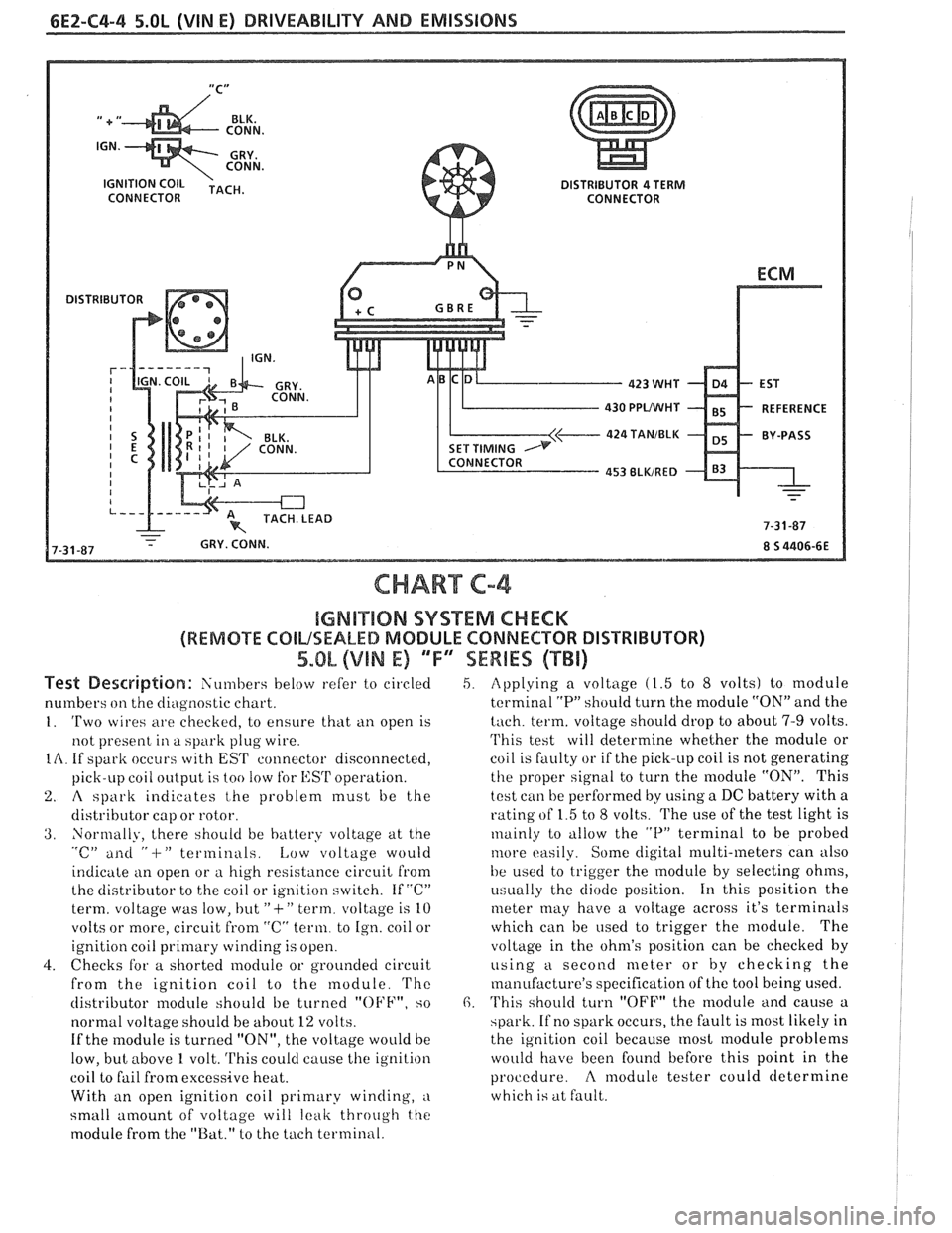
6E2-C4-4 5.OL (VIN E) DRIVEABILITY AND EMISSIONS
CONNECTOR
430 PPUWHf
424 TANIBLK
CHART C-4
IGMB"$IIQN SYSTEM CHECK
(REMOTE COILSEALED MODULE CONNECTOR DISTRIBUTOR)
5.OL (VIN E) 'TF"7SEWBES (TBi)
Test De~driptian: Siin~bers below refer to circled
numbers
on the diagilostic chart.
1. 'Two wires are checkecl, to ensure that ti11 open is
not present
in a spark plug wire.
IA. If spark occurs with EST connector disconnected,
pick-LIP coil
oiltp~it is too !OW for l,:SrI' operation.
2. A spark indicates t,he problem must be the
distributor cap or rotor.
3. Normally, there should be battery voltage at the "c" ailti " -I-" terminals. Low voltage would
indicate an open or
a high resistance circuit from
the distributor to the coil or ignition switch. If "C"
term. voltage was low, but
"+" term. voltage is 10
volts or more, circuit
from "C" term. to Ign. coil or
ignition coil
primary winding is open.
4. Checks for a shorted module or grounded circuit
from the ignition coil to the module.
'I'hc
distributor module should be turned "OFF", so
normal voltage should be
about 12 volts.
If the module is turned "ON", the voltage would be
low, but above
1 volt. This could cause the ignition
coil to fail from excessive heat.
With an open ignition coil primary winding,
a
small amount of voltage will leak throtrgh the
module from the "Bat." to the tach terminal.
5. Applying a voltage (1.5 to 8 volts) to module
terminal
"P" should turn the module "ON" and the
tach. term. voltage should drop to about 7-9 volts.
'I'his test will determine whether the module or
coil is faulty or if the pick-up coil is not generating
the proper signal to turn the module "ON". This
test can be performed by using a DC battery with a
rating of 1.5 to
8 volts. The use of the test light is
~nainly to tillow the "P" terminal to be probed
tilore easily. Some digital multi-meters can also
be used to trigger the
module by selecting ohms,
i~sually the diode position. 111 this position the
meter may have a voltage across it's terminals
which can be
used to trigger the module. The
voltage in the ohm's position can be checked
by
using a second meter or by checking the
manufacture's specification of the tool being used.
6. 'I'his should turn "OFF" the module and cause a
spark. If no spark occurs, the fault is most likely in
the ignition coil because
most module problems
would have been found before this point in the
procedure.
A modulc tester could determine
which is at fault.
Page 606 of 1825
DRIVEABILITY AND EMISSIONS 5.OL (VIN E) 6E2-C5-1
ELECmONIC SPARK CONTROL (ESC) SYSTEM
CONTENTS
GENERAL DESCRIPTION ................ C5-1 ON-CAR SERVICE ..................... C5-1
PURPOSE
......................... C5-1 ESC KNOCK SENSOR ................ C5-1
OPERATION
....................... C5-1 ESC MODULE ...........e..e.e..... C5-1
DIAGNOSIS
......................... C5-1 PARTS INFORMATION ................. C5-2
RESULTS OF INCORRECT ESC OPERATION
. C5-1
GENERAL DESCRIPTION
PURPOSE
To control spark knock, an electronic spark control
(ESC) system has been added. This system is designed
to retard spark timing up to
20°, to reduce spark knock
in the engine. This allows the engine to use maximum
spark advance to
improve driveability and fuel
economy. Varying octane levels in today's gasoline can
cause detonation in high performance engines.
Detonation is called spark knock. Loss
of the ESC signal to the ECM would cause the
ECM to constantly retard EST. This could result in
sluggish performance and cause a Code
43 to set.
A "Scan" tool will read knock signal in
AID
counts. When detonation is detected, knock signal
counts will increment,
as long as knock is present.
"Scan" tools will indicate knock being present either
by showing
AID counts, or displaying Yes (knock
present), or No (knock not present). If Code
43 is
present, use that chart to diagnose system. If no code
is present and ESC system is suspected, use CHART
C-5.
ON-CAR SERVICE
OPERATION
ESC KNOCK SENSOR
'I'he ESC system has two major components:
e ESC Module
@ ESC Knock Sensor
The sensor is mounted in the engine block near
the cylinders, or in the intake manifold at the rear of
the engine. When the ESC knock sensor detects
abnormal vibration (spark knocking) in the engine, it
produced
a voltage that is received by the ESC
module. As long as the ESC module sees no voltage
from the knock sensor (knock not present), it sends a
signal voltage
(8 to 10 volts) to the ECM and the ECM
provides normal spark advance.
When the module
d'etects voltage from the knock
sensor (knock present), it turns "OFF" the signal to
the ECM and the voltage at terminal
B7 goes to 0
volts: The ECM then retards EST to reduce spark
knock.
DIAGNOSIS
See Figure C5-1.
Remove or Disconnect
1. Negative battery cable.
2. ESC wiring harness connector from ESC sensor.
3. ESC sensor from engine block.
Install or Connect
I. ESC sensor into engine block. Apply thread
sealer, such as soft tape, to the ESC sensor
threads.
2. ESC wiring harness connector to the ESC sensor.
3. Negative battery cable.
ESC MODULE
RESULTS OF INCORRECT ESC OPERATION
Refer to Figure C5- 1
Loss of the ESC knock sensor signal or loss of
ground at ESC module would cause the signal to the a Remove or Disconnect
ECM to remain hiph. This condition would cause the 1. ESC module connector. L. ECM to control EST, as if no spark knocking were 2. Attachingscrews.
happening. No retard would occur, and spark 3. p;SCmodule.
knocking could become severe under heavy engine
load conditions.
Page 626 of 1825
DRIVEABILITY AND EMISSIONS - 5.0L (VIM E) 6E2-C8-1
SECTION C8
"FRANSMISSIBN CONVERnEW CLUTCH (TCC) SYSTEM
CONTENTS
GENERAL DESCRIPTION ............... C8-1 RESULTS OF INCORRECT TCC
PURPOSE
........................ C8-1 OPERATION ..................... C8-2
......................... OPERATION ...................... C8-1 DIAGNOSIS CS-2
.................... CIRCUIT DESCRIPTION ....e.e..eea..e C8-1 ON-CAR SERVICE C8-2
................. PARTS INFORMATION C8-2
GENERAL DESCRIPTION
PURPOSE
The transmission converter clutch (TCC) system
is designed to eliminate power loss by the converter
(slippage) thus increasing fuel economy. By locking
the converter clutch,
a more effective coupling to the
flywheel is achieved. The converter clutch is operated
by an ECM controlled solenoid.
OPERATION
Engagement of the TCC is accomplished by a
solenoid operated valve within the transmission. The
solenoid is activated when an internal switch in the
ECM is grounded. Although the ECM may command
the TCC
"ON", the converter clutch will not apply
until internal transmission fluid pressure require-
ments are met. See Section
"7A".
Before the ECM activates the TCC apply solenoid,
several inputs must be monitored:
e Vehicle Speed. Must be above a certain value
before the TCC can be applied.
Coolant Temperature. The engine coolant
temperature must be above a certain value
before the TCC can be applied.
@ Throttle Position Sensor. After the TCC is
applied, during low engine load condition, the
ECM uses the information from the TPS to
release the clutch when the car is accelerating
or decelerating at a certain rate.
CIRCUIT DESCRIPTION
When the brake pedal is not depressed (switch
closed), battery voltage will be fed to the TCC
solenoid. If the ECM has determined that conditions
are correct, the circuit from the TCC solenoid will be
completed to ground through the ECM and the TCC
solenoid will be activated.
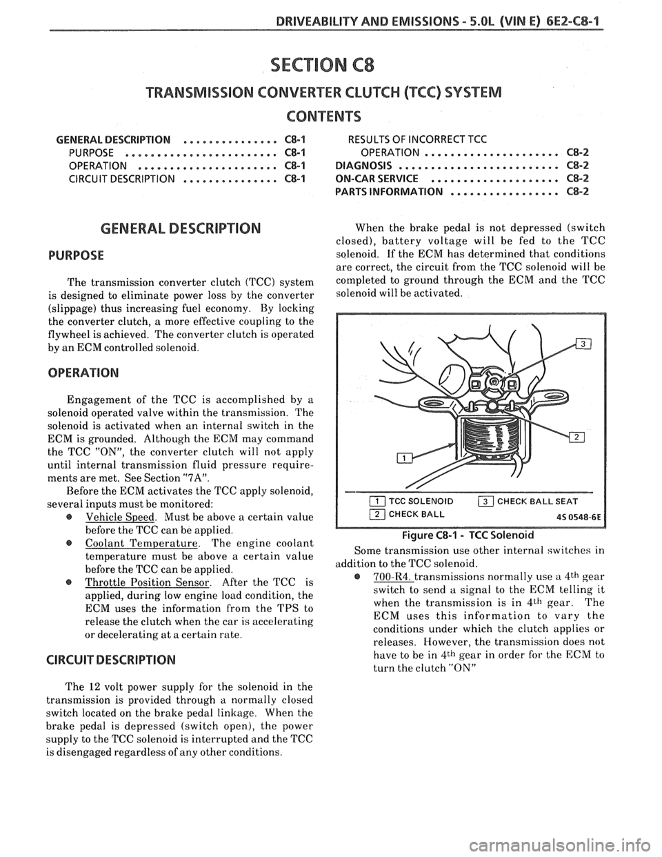
Figure C8-1 - TCC Solenoid
Some transmission use other internal switches in
addition to the TCC solenoid.
@ 700-R4. transmissions normally use a 4th gear
switch to send
a signal to the ECM telling it
when the transmission is in
4th gear. The
ECM uses this information to vary the
conditions under which the clutch applies or
releases. However, the transmission does not
have to be in
4th gear in order for the ECM to
turn the clutch
"ON"
The 12 volt power supply for the solenoid in the
transmission is provided through
a normally closed
switch located on the brake pedal linkage. When the
brake pedal is depressed (switch open), the power
supply to the TCC solenoid is interrupted and the TCC
is disengaged regardless of any other conditions.
Page 631 of 1825
6E2-C8-6 DRIVEABILITY AND EMISSIONS - 5.OL (VIN E)
I.P. HARNESS CONNECTOR 15 WAY (FRONT VIEW)
ECM
VEHICLE SPEED SIGNAL
SPEED INPUT
4TH GEAR SIGNAL
422 TANIBLK
ALDL CONNECTOR
* 85 4435-66 6-8-87
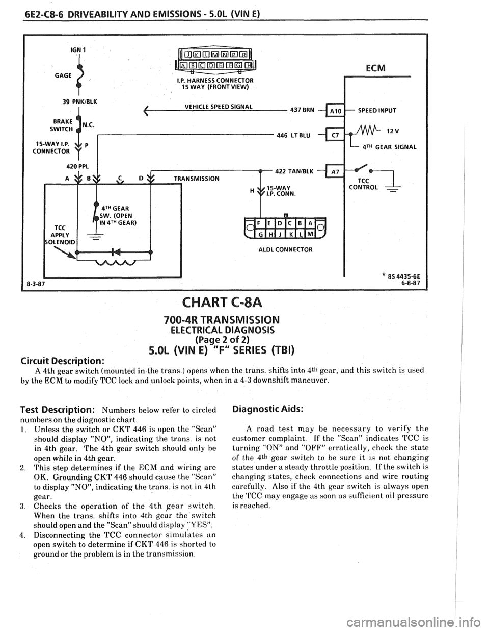
CHART C-8A
700-4R TRANSMISSION
ELECTRICAL DIAGNOSIS
(Page 2 of 2)
5.0L (VIN E) "F" "SERIES (TBI)
Circuit Description:
A 4th gear switch (mounted in the trans.) opens when the trans. shifts into 4th gear, and this switch is used
by the ECM to modify TCC lock and unlock points, when in a 4-3 downshift maneuver.
Test Description: Numbers below refer to circled
numbers on the diagnostic chart.
1. Unless the switch or CKT 446 is open the "Scan"
should display "NO", indicating the trans. is not
in 4th gear.
The 4th gear switch should only he
open whiie in 4th gear.
2. This step determines if the ECM and wiring are
OK. Grounding CKT 446 should cause the "Scan"
to display "NO", indicating the trans. is not in 4th
gear.
3. Checks the operation of the 4th gear switch.
When the trans. shifts into 4th
geir the switch
should open and the "Scan" should display
"YES".
4. Disconnecting the TCC connector simulates an
open switch to determine if CKT
446 is shorted to
ground or the problem is in the transmission.
Diagnostic Aids:
A road test may be necessary to verify the
customer complaint. If the "Scan" indicates TCC is
turning
"ON" and "OFF" erratically, check the state
of the 4th gear switch to he sure it is not changing
states under a steady throttle position.
If the switch is
changing states, check connections and wire routing
carefully. Also if the 4th gear switch is always open
the
TCC may engage as soon as sufficient oil pressure
is reached.
Page 669 of 1825
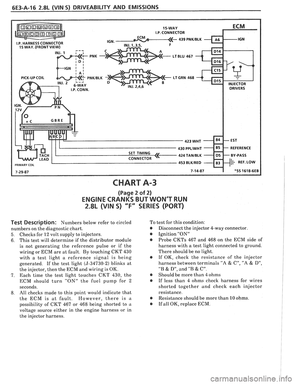
CHART A-3
(Page 2 of 2)
ENGINE CRANKS BUT WONT WN
2.8L (VIN S) ""FYSERIES (PORT)
Test Description: Numbers below refer to circled
numbers on the diagnostic chart.
5. Checks for 12 volt supply to injectors.
6. This
test will determine if the distributor module
is not generating the reference pulse or if the
wiring or ECM are at fault. By touching CKT 430
with a test light a reference signal is being
generated. If the test light
(5-34730-2) blinks at
the injector, then the ECM and wiring is OK.
7. Each time
the test light touches CKT 430, the
ECM should turn "ON" the fuel
punlp for 2
seconds.
8. All
checks made to this point would indicate that
the ECM is at fault. However, there is
a
possibility of CKT 467 or 468 being shorted to a
voltage source either in the engine harness or in
the injector harness. To
test for this condition:
@ Disconnect the injector 4-way connector.
@ Ignition "ON"
Probe
CKTs 467 and 468 on the ECM side of
harness with a test light connected to ground.
There should be no light.
@ If OK, check the resistance of the injector
harness between terminals
"A & C", "A & D",
"B & D", and .'B & C".
@ Should be more than 4 ohms
@ If less than 4 ohms check harness for wires
shorted together and check each injector
resistance.
@ Resistance should be more than 10 ohms.
@ If all OK, replace ECM.
Page 683 of 1825
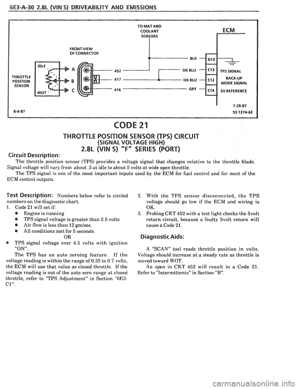
6E3-A-38 2.8b (VIM S) DRIVEABILITY AND EMISSIONS
FRONT VIEW OF CONNECTOR
MODE SIGNAL
5V REFERENCE
THRBmLE POSiT10N SENSOR (TPS) CIRCUIT
(SIGNAL VOLTAGE HIGH)
2.8L (VIN S) ""F-SERIES (PORT)
Circuit Description:
The throttle position sensor (TPS) provides a voltage signal that changes relative to the throttle blade.
Signal voltage will vary from about
.5 at idle to about 5 volts at wide open throttle.
The TPS signal is one of the most important inputs used by the ECM for fuel control and for most of the
ECM control outputs.
Test Description: Numbers below refer to circled
numbers on the diagnostic chart.
1. Code 21 will set if:
@ Engine is running
@ TPS signal voltage is greater than 2.5 volts
@ Air flow is less than 12 gmlsec.
All conditions met for 5 seconds.
OR
@ TPS signal voltage over 4.5 volts with ignition
"ON".
The TPS has an auto zeroing feature. If the
voltage reading is within the range of 0.35 to 0.7 volts,
the ECM will use that value as closed throttle.
If the
voltage reading is out of the auto zero range at closed
throttle, refer to "TPS Adjustment" in Section
"6E3-
C1".
2. With the TPS sensor disconnected, the TPS
voltage should go low if the
ECM and wiring is
OK.
3. Probing CKT 452 with a test light checks the 5volt
return circuit, because a faulty 5volt return will
cause a Code 21.
Diagnostic Aids:
A "SCAN" tool reads throttle position in volts.
Voltage should increase at a steady rate as throttle
is
moved toward WOT.
An open in CKT 452 will result in a Code 21.
Refer to "Intermittents" in Section "B".
Page 687 of 1825
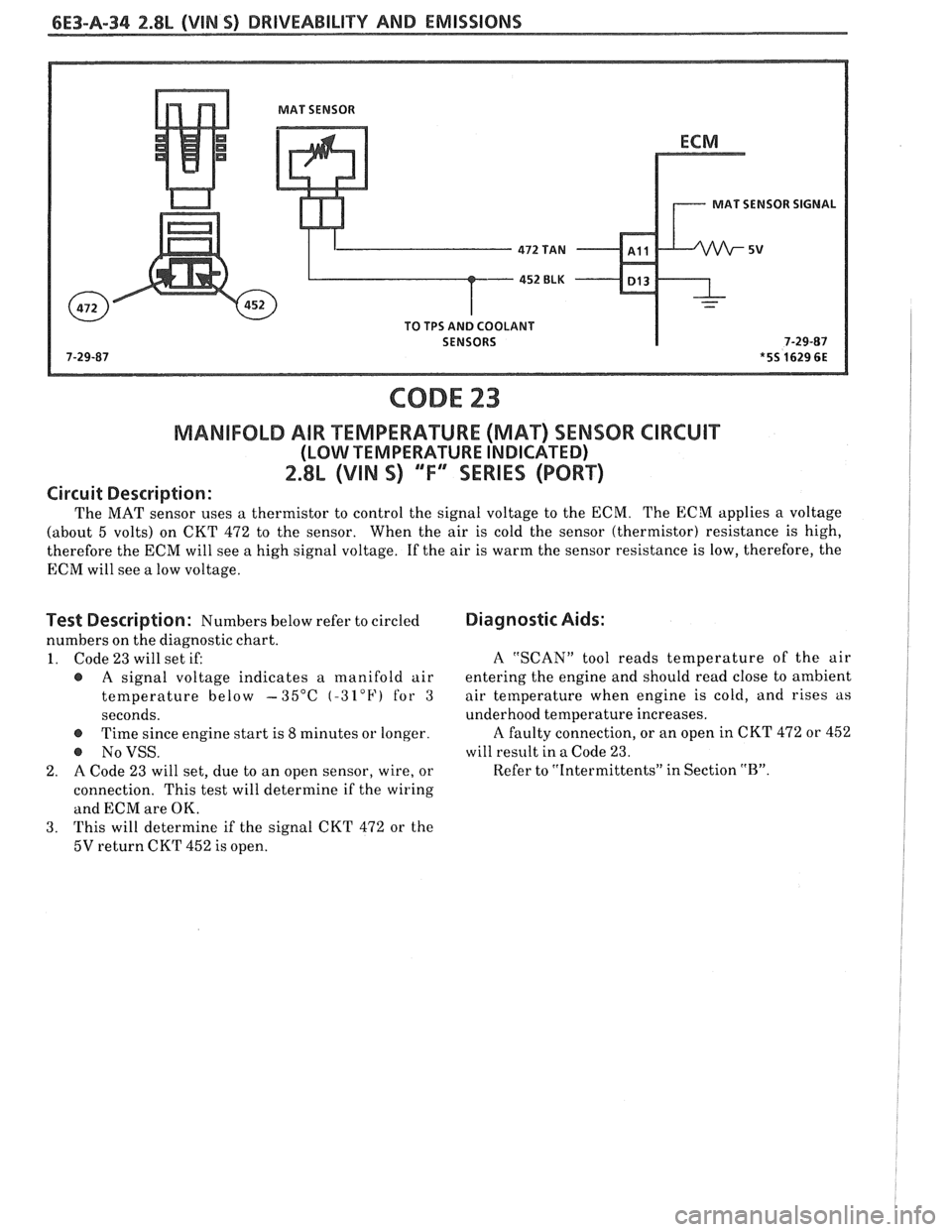
6E3-8-34 2.8L (VIN S) DRIVEABILITY AND EMISSIONS
MAT SENSOR
MAT SENSOR SIGNAL
TO TPS AND COOLANT
SENSORS
CODE 23
MANIFOLD AIR TEMPERAWRE (MAq SENSOR CIRCUIT
(LOW TEMPERATURE INDICATED)
2.8L (VIN S) "F"" SERIES (PORT)
Circuit Description:
The MAT sensor uses a thermistor to control the signal voltage to the ECM. The ECM applies a voltage
(about 5 volts) on CKT 472 to the sensor. When the air is cold the sensor (thermistor) resistance is high,
therefore the ECM will see a high signal voltage. If the air is warm the sensor resistance is low, therefore, the
ECM will see
a low voltage.
Test Description: Numbers below refer to circled
numbers on the diagnostic chart.
1. Code 23 will set if:
@ A signal voltage indicates a manifold air
temperature below
-35°C (-32°F) for 3
seconds.
@ Time since engine start is 8 minutes or longer.
@ NoVSS.
2. A Code 23 will set, due to an open sensor, wire, or
connection. This test will determine if the
wiring
and ECM are OK.
3. This
will determine if the signal CKT
472 or the
5V return CKT 452 is open.
Diagnostic Aids:
A "SCAN" tool reads temperature of the air
entering the engine and should read close to ambient
air tetnperature when engine is cold, and rises as
underhood temperature increases.
A faulty connection, or an open in CKT 472 or 452
will result in a Code 23.
Refer to "Intermittents" in Section
"B".
Page 693 of 1825
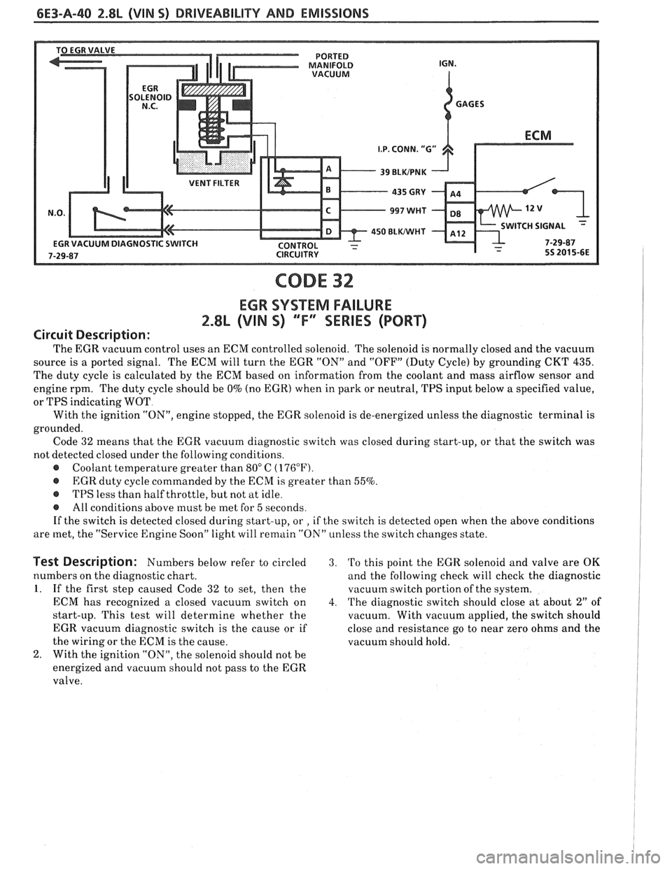
6E3-A-40 2.8L (VIN 5) DRIVEABILITY AND EMISSIONS
VENT FILTER
450 BLWHT ITCH SIGNAL -
CODE 32
EGR SYSTEM FAILURE
2.8L (VIN S) "F" "SERIES (PORT)
Circuit Description:
The EGR vacuum control uses an ECM controlled solenoid. The solenoid is normally closed and the vacuum
source is a ported signal. The ECM will turn the EGR "ON" and "OFF" (Duty Cycle) by grounding CKT
435.
The duty cycle is calculated by the ECM based on information from the coolant and mass airflow sensor and
engine rpm. The duty cycle should be
0% (no EGR) when in park or neutral, TPS input below a specified value,
or TPS indicating WOT
With the ignition
"ON", engine stopped, the EGR solenoid is de-energized unless the diagnostic terminal is
grounded. Code 32 means that the EGR vacuum diagnostic switch was closed during start-up, or that the switch was
not detected closed under the following conditions.
@ Coolant temperature greater than 80" C (176°F).
@ EGR duty cycle commanded by the ECM is greater than 55%.
@ TPS less than half throttle, but not at idle.
@ All conditions above must be met for 5 seconds.
If the switch is detected closed during start-up, or
, if the switch is detected open when the above conditions
are met, the "Service Engine Soon" light will remain "ON" unless the switch changes state.
Test Description: Numbers below refer to circled 3. 'Po this point the EGR solenoid and valve are OK
numbers on the diagnostic chart. and the following check will check the diagnostic
1. If the first step caused Code 32 to set, then the vacuutn switch portion of the system.
ECM has recognized a closed vacuum switch on
4. The diagnostic switch should close at about 2" of
start-up. This test will determine whether the
vacuum. With vacuum applied, the switch should
EGR vacuum diagnostic switch is the cause or if close and resistance go to near zero ohms and the
the wiring or the ECM is the cause. vacuum should hold.
2. With the ignition "ON", the solenoid should not be
energized and vacuum should not pass to the EGR
valve.