1988 PONTIAC FIERO turn signal
[x] Cancel search: turn signalPage 1666 of 1825

CRUISE CONTROL 98-3
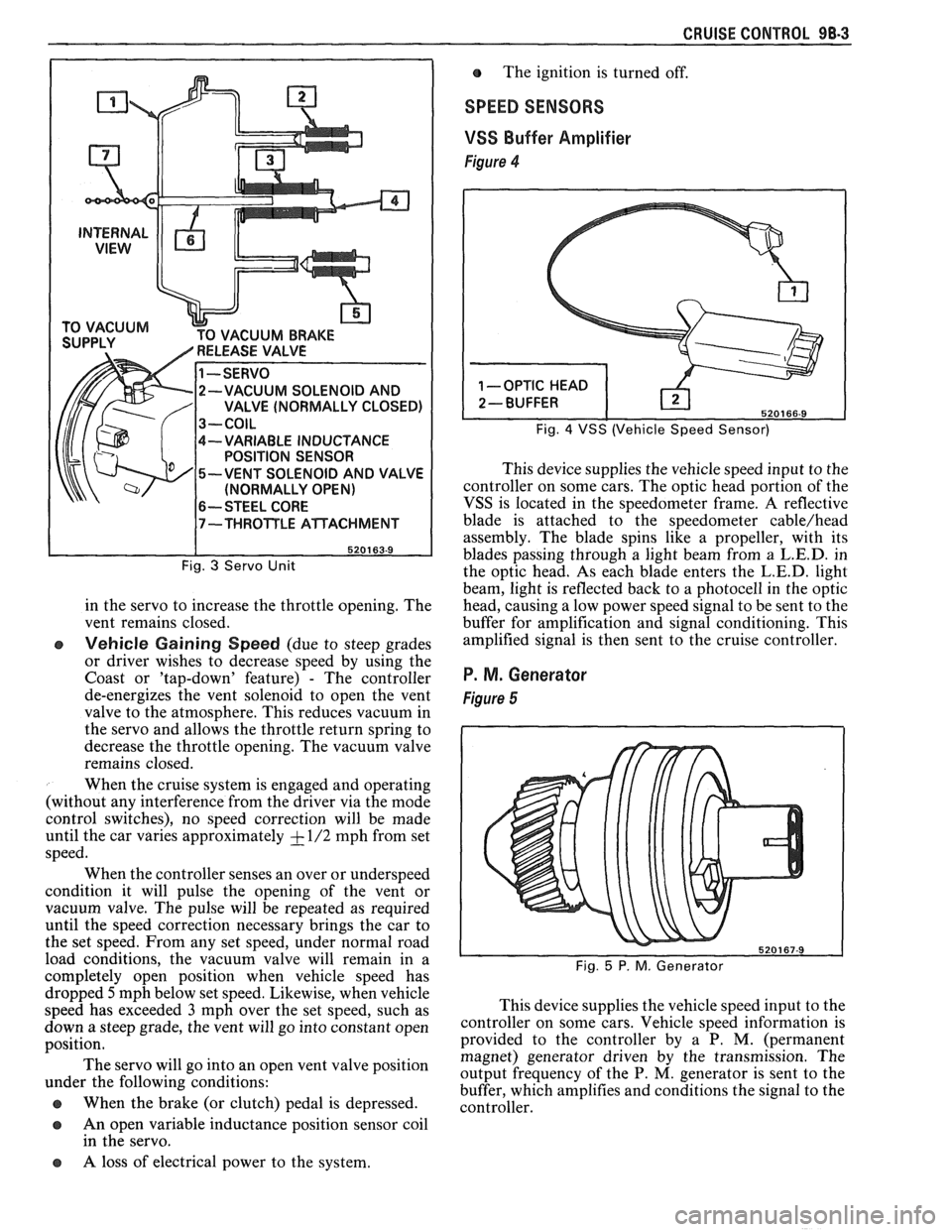
CUUM BRAKE
-VARIABLE INDUCTANCE
POSITION SENSOR
-VENT SOLENOID AND VALVE
(NORMALLY OPEN)
6-- STEEL CORE
Fig. 3 Servo Unit
in the servo to increase the throttle opening. The
vent remains closed.
e Vehicle Gaining Speed (due to steep grades
or driver wishes to decrease speed by using the
Coast or 'tap-down' feature)
- The controller
de-energizes the vent solenoid to open the vent
valve to the atmosphere. This reduces vacuum in
the servo and allows the throttle return spring to
decrease the throttle opening. The vacuum valve
remains closed.
When the cruise system is engaged and operating
(without any interference from the driver via the mode
control switches), no speed correction will be made
until the car varies approximately
+ - 1/2 mph from set
speed.
When the controller senses an over or underspeed
condition it will pulse the opening of the vent or
vacuum valve. The pulse will be repeated as required
until the speed correction necessary brings the car to
the set speed. From any set speed, under normal road
load conditions, the vacuum valve will remain in a
completely open position when vehicle speed has The
ignition is turned off.
SPEED SENSORS
VSS
Buffer Amplifier
Figure 4
Fig. 4 VSS (Vehicle Speed Sensor)
This device supplies the vehicle speed input to the
controller on some cars. The optic head portion of the
VSS is located in the speedometer frame. A reflective
blade is attached to the speedometer
cable/head
assembly. The blade spins like a propeller, with its
blades passing through a light beam from a
L.E.D. in
the optic head. As each blade enters the
L.E.D. light
beam, light is reflected back to a photocell in the optic
head, causing a low power speed signal to be sent to the
buffer for amplification and signal conditioning. This
amplified signal is then sent to the cruise controller.
P. M. Generator
Figure 5
dropped 5mph below set speed. Likewise, when vehicle
speed has exceeded
3 mph over the set speed, such as This
device supplies the vehicle speed input to the
down a steep grade, the vent will go into ,-onstant open ~0ntI-011er on some cars. Vehicle speed information is
position. provided
to the controller by a P. M. (permanent
magnet) generator driven by the transmission. The
The servo go into an 'Pen vent position output frequency of the P. M, generator is sent to the under the following conditions:
buffer, which amplifies and conditions the signal to the
@ When the brake (or clutch) pedal is depressed. controller.
a An open variable inductance position sensor coil
in the servo.
a A loss of electrical power to the system.
Page 1675 of 1825

9G-2 MISCELLANEOUS ACCESSORIES
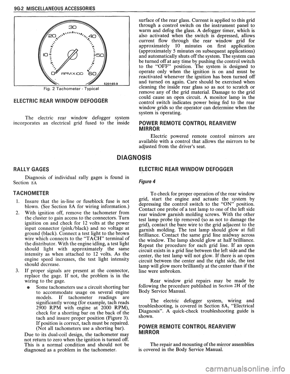
Fig. 2 Tachometer - Typical
RPMX I00 €31-
ELECTRIC REAR WINDOW DEFOGGER
surface of the rear glass. Current is applied to this grid
through a control switch on the instrument panel to
warm and defog the glass. A defogger timer, which is
also activated when the switch is depressed, allows
current flow through the rear window grid
for
approximately 10 minutes on first application
(approximately
5 minutes on subsequent applications)
and automatically shuts off the system. The system can
be turned off at any time by pushing the control switch
to the "OFF" position. The system is designed to
operate only when the ignition is on and must be
reactivated whenever the ignition has been turned off
and turned on again. Care should be exercised when
cleaning the inside rear glass so as not to scratch or
remove any of the grid material. Damage to the grid
could cause an open circuit. A monitor lamp in-the
control switch indicates power being fed to the rear
window grids so the operator can determine when the
system is operating.
The electric rear window defogger system
incorporates an electrical grid fused to the inside
POWER REMOTE CONTROL REARVIEW
MIRROR
Electric powered remote control mirrors are
available with a control that allows the mirrors to be
adjusted from the driver's seat.
RALLY GAGES ELECTRIC REAR WINDOW DEFOGGER
Diagnosis of individual rally gages is found in
Section
8A Figure 4
TACHOMETER To check for moper o~eration of the rear window
1. Insure that the in-line or fuseblock fuse is not
blown. (See Section 8A for wiring information.)
2. With ignition off, remove the tachometer from
the cluster to gain access to the connectors. Turn
ignition on and check for
12 volts at the power
input connector
(pink/black) and no voltage at
ground (black). Connect a test light to the brown
wire which connects to the "TACH" terminal of
the distributor. With the engine idling, a test light
should light with approximately the same
intensity as when attached to
12 volts. As the
engine speed increases, the test light intensity
should decrease.
3. If proper signals are present at the connector,
replace the gage. If not, the problem is in the
wiring to the gage.
Some tachometers use a circuit shorting bar
to accommodate usage on several engine
models. If tachometer readings are
significantly wrong (for example, tach reads
2900 RPM with engine at 2000 RPM),
check for a shorting bar on the back of the
tach and insure proper position (Figure
3).
If position is correct, tach must be repaired.
(Not all tachometers use a shorting bar).
Due to its dual-coil design, the tachometer
may
- grid, start the engine a& actuate the system by
depressing the control switch to the
"ON" position.
Contact one probe of a test lamp to one of the left side
rear window garnish molding screws. With the other
test lamp probe tip removed (so as not to damage the
grid), contact the bare wire to the grid adjacent to the
garnish molding. The test lamp should glow at full
brilliance. Contact the same grid line midway across
the window. The lamp should glow at half brilliance.
Repeat the procedure for each grid line. If an open
circuit exists in a grid line between the left side and the
center, the test lamp will not glow. If there is an open
circuit between the center and the right side, the test
lamp will glow more brilliantly at the center than if the
line were unbroken.
Rear window grid repairs may be made by
following the procedure published in
Section 2H of the
Body Service Manual.
The electric defogger system, wiring and
troubleshooting, is covered in Section
8A, "Electrical
Diagnosis". A quick-check troubleshooting guide is
shown.
POWER REMOTE CONTROL REARVIEW
MIRROR
not return to zero when tvhe ignition is turned off'.
This is a normal condition and should not be The
repair and mounting of the mirror assemblies
diagnosed as a problem in the tachometer. is
covered in the Body Service Manual.
Page 1784 of 1825

SEATS - F STYLE 9H-1
SEC"IC"0N 9H
SEATS
NOTICE: Lap belt to floor pan and shoulder belt to roof panel or quarter panel fasteners are important
attaching parts in that they could affect the performance of vital parts and systems, and/or could result in major
repair expense. They must be replaced with one of the same part number or with an equivalent part if replacement
becomes necessary. Do not use a replacement part of lesser quality or substitute design. Torque values must be
used as specified during reassembly to assure proper retention of these parts.
CONTENTS
Restraint Systems ........................................... 9H- 1
Lap and Shoulder Belts
............................... 9H-1
Comfort Lock Operational Checks
and Requirements
.................................... 9H- 1
Front Seat Shoulder Belt Retractor
............ 9H-2
Child Seat
...................................................... 9H-2
............................... .................. -.rant Seats .. 9H-5
Mead Restraint
............................................. 9H-5
Reclining
Seatback ................................... 9H-6
Front
Seatback ........................................... 9H-7
Inertia Lock Check
...................................... 9H-7
............................... Manual Recliner Check 9H-7
........................... Seat Torque Specifications 9H-8
Manual Seat
- Diagnosis Chart ................... 9H-8
..................... Power Seat - Diagnosis Chart 9H-9
RESTRAINT SYSTEMS
LAP
AND SHOULDER BELTS
The front seat belts incorporate a 4-to-8 second
fasten seat belt reminder lamp and sound signal
designed to remind the driver if the lap and shoulder
belts are not fastened when the ignition is turned to the
on position. If the driver's seat belt
is buckled, the
alarm will not operate; however, the fasten seat belt
xminder lamp will stay on for a 4-to-8 second period.
,, the driver's seat belt is not buckled, the reminder
lamp and sound signal will automatically shut off after
the 4-to-8 second interval. To diagnose a system
failure, refer to Seat Belt Reminder
Lamp/Alarm
Diagnosis in Section 8A.
The shoulder belt is attached to the front seat lap
belt latch plate and connected to an inertia locking
retractor installed to the roof panel above the right and
left side of the front seat. The shoulder belt remains
unlocked to allow the occupants to move freely while
the vehicle is being operated. When the vehicle
decelerates or changes direction abruptly, the shoulder
belt is locked in position by a pendulum that causes a
locking bar to engage a cog of the retractor mechanism.
The retractor has a comfort lock feature that
allows the occupant to adjust the shoulder belt for
proper fit and comfort. When engaged, the comfort
lock prevents full retraction of the webbing to eliminate
occupant discomfort due to webbing load on the
shoulder. The occupant can readjust the comfort lock
during vehicle operation as described below.
When servicing or replacing lap and shoulder
belts, refer to the following precautionary items: Front
Seat Adjustments
............................... 9H- 10
Manual Seat Control Arm Knob
................ 9H-10
Front Seat Assembly
.................................... 9H- 1 1
Seat Adjuster Assembly ............................. 9H-11
Six-way Seat Adjuster .................................. 9H- 12
Power Seat Switch
........................................ 9H-15
Four-way Manual Seat Adjuster
................. 9H-15
Seatback Lock Striker/Side Bar Stop .......... 9H-15
High Performance AQ9 Seat
(2FS87) ......... 9H-15
................. .................................... Rear Seats ... 9H- 19
........................................ Cushion Assembly 9H- 19
................................ Folding Rear Seatback 9H- 19
........................... Seatback Lock Assembly 9H-20
.................................. Seatback Lock Striker 9H-20
1. Lap and shoulder belts will be serviced as follows:
a. Retractor
portion(s) of
front seat lap and
shoulder belt for outboard passenger and
driver.
b. Buckle portion of front seat lap belt for
outboard passenger and driver.
c. All belts other than those mentioned in
above steps a and b will be serviced in
complete sets.
d. Do not intermix standard and deluxe belts
on front or rear seats.
2. Keep sharp edges and damaging objects away
from belts.
3. Avoid bending or damaging any portion of the
belt buckle or latch plate.
4. Do not bleach or dye belt webbing (clean with a
mild soap solution and water).
5. When installing lap or shoulder belt anchor bolt,
start bolt by hand to assure that bolt is threaded
straight.
NOTICE: See NOTICE on page 9H-1 of this
section.
6. Do not attempt repairs on lap or shoulder belt
retractor mechanisms or lap belt retractor covers.
Replace with new service replacement parts.
Comfort Lock Operational Checks and Requirements
The shoulder belt comfort lock feature must
function as follows:
1. Extend the webbing from the retractor to a
distance approximating buckled position.
Page 1823 of 1825

8- CHASSIS INDEX
Recommended Fluids and Lubricants ................ OB-6
Relay Rod
......................................................... 3B6-2
Remote Mirror Control
...... See Body Service Section
5H.1. 15
Repair Procedures
.......................................... 88-50
S
........................................ Scheduled Maintenance OB- 1
Seats (Power) ....................................... Lumbar Support 8A- 145-0
............................. Sequential Fuel Injection 6E3-C2- 1
Service Engine Soon Light
.................................... 8C-3
Sheet Metal and Grille
................................ Section 2C
......................................... General Description .2 C. 1
........................................... Service Procedures .2 C. 1
................................................................. Hood .2 C. 1
...................................................... Hood Hinge 2C-2
Hood Latch and Cable
...................................... 2C-2
Paint
.............................................. Color Matching 2C-5
................................................ Identification -32-6
Interior Plastic Parts ...................................... 2C-6
................................................ Shock Absorbers 3D-
1
Shoe and Lining Assembly
. Brake
............................................ 3000/3 100 Series 5B1-3
3548 Series ...................................................... 5B6-4
Side Marker Lights
.............................................. 8B-2
........ Speakers See 8A- 150-0 & Body
Manual Section
6H- 1
.................... Spark Plug Gap .. .................. 6E3-13-3
................................ Speaker and Speaker Grille 9A-9
Special Tools
............................................ Air Conditioning 1 B-3 5
Air Conditioning Compressor
................................................. Overhaul 1D1-21
........................ Automatic Transaxle AT-700-R4-64
................................................................ Brakes SF-1
Clutch ................................................................ 7C-8
................................................................ Rear 4B1-20
....................................... Rear (Borg Warner) 4B-20
........................... Driveability and Emissions .6 E. 17
................................................ Engine Cooling 6B- 14
Power Steering Pump
& Gear ...................... 3B7-17
............................................... Propeller Shaft .4 A. 12
Steering Wheels and Columns
.......................... 5-35
Specifications Automatic Transmission Unit
............................................ Repair AT-700-R4-59
..................................................... Battery 6D 1-7
................................................................ Brakes 5F-1
Bumpers
......................................................... 2B-5
Charging System
................ .. ................... 6D3-3
.............................................................. Clutch .7 (2.8
....................................... Cranking System 6D2- 1 1
Driveability and Emissions ............................ 6E-23
................................................ Engine (V-6) ..6A 2.26
Engine (V-8) .................................................. 683-28
........................................ Front Suspension 3C- 10
Power Steering Gear and Pump
.................. 3B7-18 ............................................. Propeller Shaft .4 A. 12 ........................................................ Rear Axle 4B-19 ............................ Rear Axle (Borg Warner) 4B 1- 19
Rear Suspension
.............................................. 3D-9
.......................................... Replacement Bulbs 8Br 10 .............................................. Steering Linkage 3B6-6
Steering Wheels and Columns
...................... 3B5-35
........................................ Wheel Alignments 3A-4
....................................................... Speedometer 8C-2
........................................ Speedometer (Removal) 8C-5
...................................................... Speed Sensors 8C-1
Starter ........................................ Section 6D2. 8A-30-0
............................................. Starter (Circuit) 8A-30-0
Steering Linkage ...................................... Section 3B6
....................................... General Description 3B6-1
........................ Maintenance and Adjustments 3B6-1
................................................ On-Car Service 3B6-2
..................................................... Idler Arm 3B6-4
................................................ Pitman Arm 3B6-5
.................................................... Relay Rod 3B6-3
Tie Rods
...................................................... 3B6-2
.................................................. Specifications 3B6-6
Steering, Suspension, Tires and
Wheels Diagnosis
............................................................. 3-1
Steering Wheels and Columns
............................ 3B5-1
..................................... General Information 3B5- 1
Maintenance and Adjustments
...................... 3B5-'
On-Car Service .............................. .. ........... 3B5
Checking for Accident Damage
.................. 3B5-5
Intermediate Shaft ............... .. .................... 3B5-3
Park Lock Cable .......................................... 3B5-4
Standard Column
............................. Automatic Transaxle 3B5-13
Manual Transaxle ................................. 3B5- 19
Tilt Column
.............................. Automatic Transaxle 3B5-27
.................................. Manual Transaxle 3B5-19
Unit Repair Intermediate Shaft
...................................................... Assembly 3B5-6
................................................. Special Tools 3B5-35
Torque Specifications
.................................... 3B5-35
............................................. Starting System 8A-30-0
........................................ Strut Assembly (Front) 3C-4
.................................... ..... Symbols Chart ... 8A-3-0
T
.......................................................... Tachometer 9G-1
Tail/Stop/Turn Signal/Lights .......................... 8B-2
Temperature Cable
.............................................. 112 A-
Temperature Warning Light ................................ 8C-3
Theft Deterrent (Circuit)
.............................. 8A-133-0
Tie Rods
.............................................................. 3B6-2
Tires and Wheels
........................................ Section 3E
Diagnosis
.................................................. Section 3
General Information
......................................... 3E-1
................................................... Metric Tires 3E-2
....................................... Replacement Tires .31 E-
.................................................... Tire Placard 3E-2
........................................................... Wheels 3E-2
Maintenance and Adjustments
.......................... 3E-2
.......................... Aluminum Wheel Cleaning 3E-9
............................. ......... Inflation of Tires .. 3E-3
........................................ Tire Chain Usage 3E-4
.................................................. Tire Rotation 3E-3
.............................................. Wheel Repair 3E-2
...................................... Wheel Studs/Nuts 3E-3
........................................... Service Operations 3E-4
........................ Aluminum Wheel Cleaning 3E-9
.................................... Balance Precautions 3E-7
............................ Balancing Tire and Wheel 3E-7
.............................................. Compact Spare 3E-6
........................ Correcting Nonuniform Tires 3E-8