1988 PONTIAC FIERO turn signal
[x] Cancel search: turn signalPage 470 of 1825
IGNITION SYSTEM 6D4-1
ON SYSTEM
CONTENTS
General Description ............................... 6D4-1 Service Procedures ............................. 6D4-3
Ignition System .......................................... 6D4-1
Ignition System .......................................... 6D4-3
Distributor Ignition ................................ 6D4-1
Distributor Ignition ................................ 6D4 -3
Diannosis .................................................... 6D4-3 On-Car Service ......................................... 6D4-5 -
Ignition System .......................................... (334-3 Ignition System ........................... .. .............. 6D4-5
Distributor ................................................. 6D4 -7 HE1 Distributor .................................... 6D4-3
GENERAL DESCRIPION
The engine electrical system includes the battery,
ignition (primary and secondary), starter (and related
wiring) and the generator (and related wiring).
Diagnostic charts (see Section 6D) will aid in
trouble-shooting system faults. When a fault is traced
to a particular component, refer to that components'
section of the service manual.
IGNITION SYSTEM
Distributor Ignition
The ignition circuit consists of the battery,
distributor, ignition switch, spark plugs and primary
and secondary wiring. Refer to the Battery portion of
this section for battery information.
PIE1 Distributor
The Nigh Energy Ignition (HEI) distributor with
Electronic Spark Timing (EST), used on most engines,
combines all ignition components in one unit. The
ignition coil is in the distributor cap and connects
through a resistance brush to the rotor.
The distributor has an internal magnetic pick-up
assembly which contains a permanent magnet, a pole
piece with internal teeth and a pick-up coil. When the
teeth of the timer core, rotating inside the pole piece,
line up with the teeth of the pole piece, an induced
voltage in the pick-up coil signals the electronic module
to trigger the coil primary circuit. The primary current
decreases and a high voltage is induced in the ignition
coil secondary winding. This voltage is directed
through the rotor and secondary leads to fire the spark
plugs. The capacitor in the distributor is for radio noise
suppression,
All spark timing changes in the
HE1 (EST)
distributor are done electronically by an Electronic
Control Module (ECM), which monitors information
from various engine sensors, computes the desired
spark timing and signals the distributor to change the
timing accordingly.
A back-up spark advance system
is incorporated to signal the ignition module in case of
(ECM) failure. No vacuum or mechanical advance is
used. Further (EST) information is found in sections 6E
Emissions Control, and
8A Electrical
Troubleshooting.
Ignition Timing
Timing specifications for each engine are listed in
Section
6E. When using a timing light, connect an
adapter between the No. 1 spark plug and the No. 1
spark plug wire, or use an inductive type pick-up.
Do
not pierce the plug lead.
Once the insulation of the
spark plug cable has been broken, voltage will jump to
the nearest ground, and the spark plug will not fire
properly.
Always follow the tune-up label
procedures when adjusting timing.
Some engines will incorporate a magnetic timing
probe hole for use with special electronic timing
equipment. Fig.
1A shows a typical magnetic probe
hole. Consult manufacturer's instructions for use of
this equipment.
Secondary Wiring
The spark plug wiring used with ignition systems
is a carbon impregnated cord conductor, encased in an
8MM (5/16") diameter silicone rubber jacket. The
silicone jacket withstands very high temperatures and
also provides an excellent insulator for the higher
voltage of the
HE1 system. Silicone spark plug boots
form a tight seal on the plug.
The boot should be
twisted 1/2 turn before removing. Care should
also be exercised when connecting a timing light or
other pick-up equipment. Do not force anything
between the boot and wiring, or through the silicone
jacket. Connections should be made in parallel using
an adapter. DO NOT pull on the wire to remove. Pull
on the boot, or use a tool designed for this purpose.
Spark Plugs
Resistor type, tapered seat spark plugs are used
on all engines (except aluminum heads). No gasket is
used on these tapered seat plugs. See Figs.
1B and 1C
for an explanation of coding on spark plugs.
Normal service is assumed to be a mixture of
idling, slow speed, and high speed driving. Occasional
or intermittent high-speed driving is needed for good
Page 519 of 1825
6EZ-A-28 5.OL (VIN E) DRIVEABILITY AND EMISSIONS
FRONT VIEW OF CONNECTOR
5V REFERENCE
TO
MAP SENSOR
CODE 21
THROTLE POSITION SENSOR (TPS) CIRCUIT
(SIGNAL VOLTAGE HIGH)
5.OL (VIN E) "F" "SERIES ("FBI)
Circuit Description:
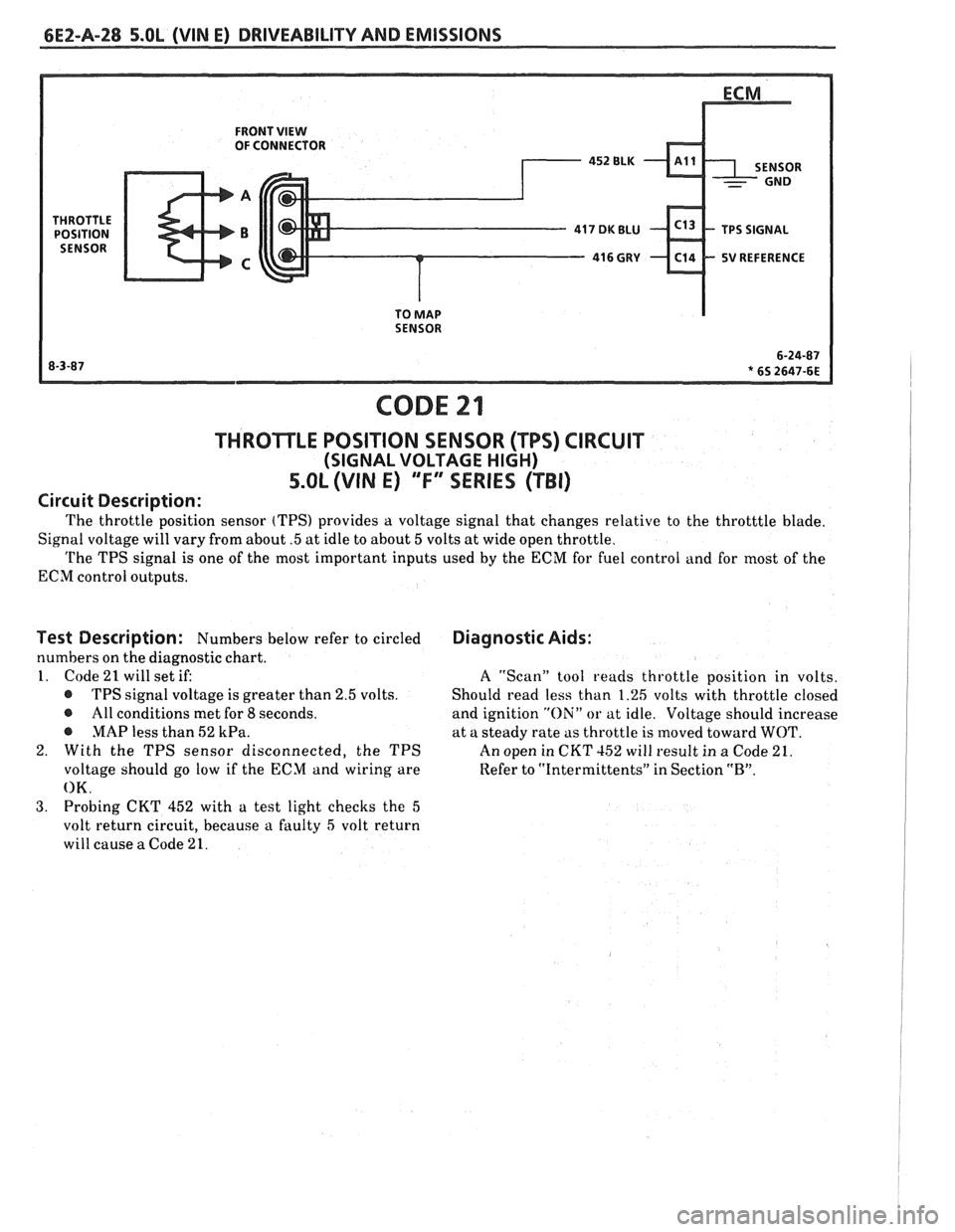
The throttle position sensor (TPS) provides a voltage signal that changes relative to the throtttle blade.
Signal voltage will vary from about
.5 at idle to about 5 volts at wide open throttle.
The TPS signal is one of the most important inputs used by the ECM for fuel control and for most of the
ECM control outputs.
Test Description: Numbers below refer to circled
numbers on the diagnostic chart.
1. Code
21 will set if:
@ TPS signal voltage is greater than 2.5 volts.
@ All conditions met for 8 seconds.
@ MAP less than 52 kPa.
2. With the TPS sensor disconnected, the TPS
voltage should go low if the ECM and wiring are
OK.
3. Probing CKT 452 with a test light checks the 5
volt return circuit, because a faulty 5 volt return
will cause
a Code 21.
Diagnostic Aids:
A ''Scan" tool reads throttle position in volts.
Should read less than 1.26 volts with throttle closed
and ignition
"Oili" or at idle. Voltage should increase
at a steady rate as throttle is moved toward
WOT.
An open in CKT 152 will result in a Code 21.
Refer to
"Intermittents" in Section "B".
Page 525 of 1825
6EZ-A-34 5.OL (WIN E) DRIVEABILITY AND EMISSIONS
ECM
I.P.
8RN 437
K 7 PIN SIGNAL
PIN SWITCH
r ELK450 12v
1 CLOSED IN - 15- WAY .I.P. CONNECTOR - - PARK OR NEUTRAL I
CODE 24
VEHICLE SPEED SENSOR (VSS) CIRCUIT
5.OL (VIN E) "F" SERIES (TBI)
Circuit Description:
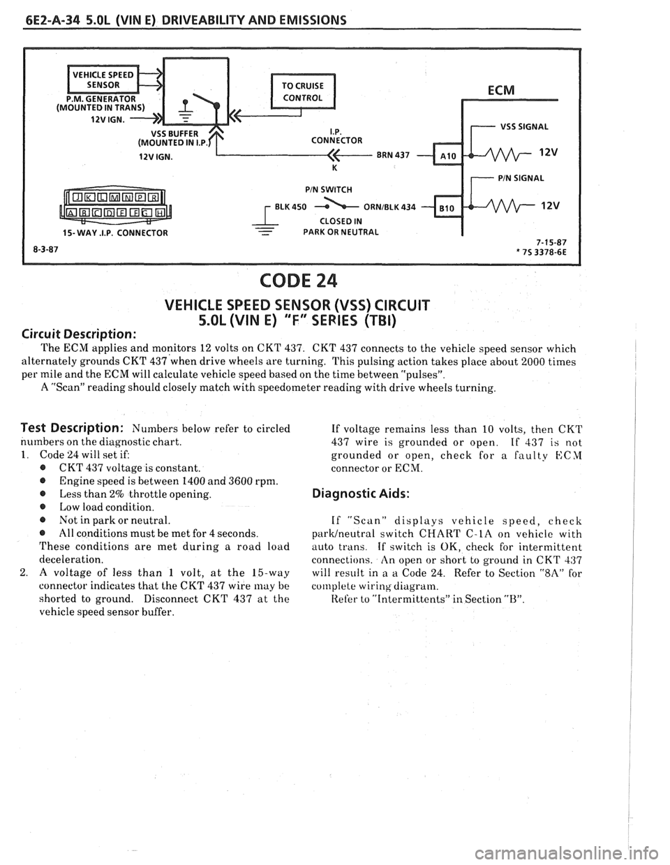
The ECM applies and monitors 12 volts on CKT 437. CKT 437 connects to the vehicle speed sensor which
alternately grounds CKT
437'when drive wheels are turning. This pulsing action takes place about 2000 times I
per mile and the ECM will calculate vehicle speed based on the time between "pulsesJ'.
A "Scan" reading should closely match with speedometer reading with drive wheels turning.
I
Test Description: Numbers below refer to circled
numbers on the diagnostic chart.
1. Code 24 will set if:
@ CKT 437 voltage is constant.
@ Engine speed is between 1400 and 3600 rpm.
@ Less than 2% throttle opening.
@ Low load condition.
@ Not in park or neutral.
@ All conditions must be met for 4 seconds.
These conditions are met during a road load
deceleration.
2.
A voltage of less than 1 volt, at the 15-way
connector indicates that the CKT 437 wire
may be
shorted to ground.
Disconnect CKT 437 at the
vehicle speed sensor buffer. If
voltage remains less than 10 volts, then CKT
437 wire is grounded or open.
If 437 is not
grounded or open, check for a faulty
KCYI
connector or ECM.
Diagnostic Aids:
If "Scan" displays vehicle speed, check
parWneutra1 switch CHART C-LA on vehicle with
auto trans.
If switch is OK, check for intermittent
connections.
An open or short to ground in CKT 437
will result in
a a Code 24. Refer to Section "$A" for
col~lplete wiring diagram.
Refer to
"[ntermittents" in Section "B".
Page 537 of 1825
CODE 43
ELECTRONIC SPARK CONTROL (ESC) CIRCUIT
5.0L (VIN E) "F" SERIES (TBI)
Circuit Description:
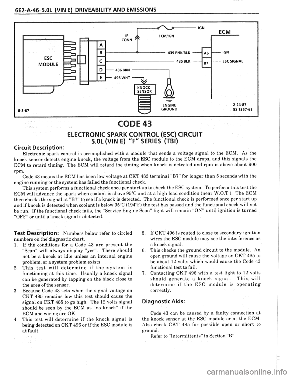
Electronic spark control is accomplished with a module that sends a voltage signal to the ECM. As the
knock sensor detects engine knock, the voltage from the ESC module to the ECM drops, and this signals the
ECM to retard timing. The ECM will retard the timing when knock is detected and rpm is above about 900
rpm. Code 43 means the ECM has been low voltage at CKT 485 terminal
"B7" for longer than 5 seconds with the
engine running or the system has failed the functional check.
This system performs a functional check once per start up to check the ESC system. To perform this test the
ECM will advance the spark when coolant is above 95°C and at
a high load condition (near W.O.T.). The ECM
then checks the signal at
"B7" to see if a knock is detected. The functional check is performed once per start up
and if knock is detected when coolant is below 95°C (194°F) the test has passed and the functional check will not
be run. If the functional check fails, the "Service Engine Soon" light will
remain "ON" until ignition is turned
"OFF" or until a knock signal is detected.
Test Description: Numbers below refer to circled
numbers on the diagnostic chart.
1. If the conditions for a Code 43 are present the
"Scan" will always display "yes". There should
not be a knock at idle unless an internal engine
problem, or a system problem exists.
2. This test will determine if the system is
functioning at this time. Usually a
knock signal
can be generated by tapping on the block close to
the area of the sensor.
3. Because Code 43 sets when the signal voltage on
CKT 485 remains low this test should cause the
signal on CKT 485 to go high. The
12 volts signal
should be seen by the ECM as "no knock"
it' the
ECM and wiring are OK.
4.
This test will determine if the knock signal is
being detected on CKT 496 or if the ESC module is
at fault. 5.
If
CKT 496 is routed to close to secondary ignition
wires the ESC
module may see the interference as
a knock signal.
6. This checks the ground circuit to the module. An
open ground will cause the voltage on CKT 485 to
be about
12 volts which would cause the Code 43
functional test to fail.
7. Contacting
CKT 496 with a test light to
12 volts
should generate a knock signal.
This will
determine if the ESC nodule is operating
correctly.
Diagnostic Aids:
Code 43 can be caused by a faulty connection at
the knock sensor at the ESC
lnodule or at the ECM.
Also check CKT 485 for possible open or short to
ground.
Iiefer to "Intcrmittents" in Section "B".
Page 543 of 1825
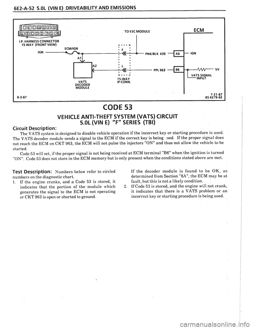
PNWBLK 439
CODE 53
VEHICLE ANTI-THEFT SYSTEM (VATS) CIRCUIT
5.OL (VIM E) "F" SERIES (TBI)
Circuit Description:
The VATS system is designed to disable vehicle operation if the incorrect key or starting procedure is used.
The VATS decoder module sends a signal to the ECM if the correct key is being
:sed. If the proper signal does
not reach the ECM on CKT 963, the ECM will not pulse the injectors
"ON" and thus not allow the vehicle to be
started. Code
53 will set, if the proper signal is not being received at ECM terminal "B6" when the ignition is turned
"ON". Code 53 does not store in the ECM memory but is only present when the conditions stated above are met.
Test Description: Numbers below refer to circled If the decoder module is found to be OK, as
numbers on the diagnostic chart. determined
from Section
"SA", the ECM may be at
1. If the engine cranks, and a Code 53 is stored, it Fault,
but this is not a likely condition.
indicates that the portion of the module which
2. If Code 53 is stored, and the engine will not crank,
generates the signal to the ECM is not operating it indicates
that there is a VATS problem or an
or CKT 963 is open or shorted to ground. incorrect
key or starting procedure is being used.
Page 545 of 1825
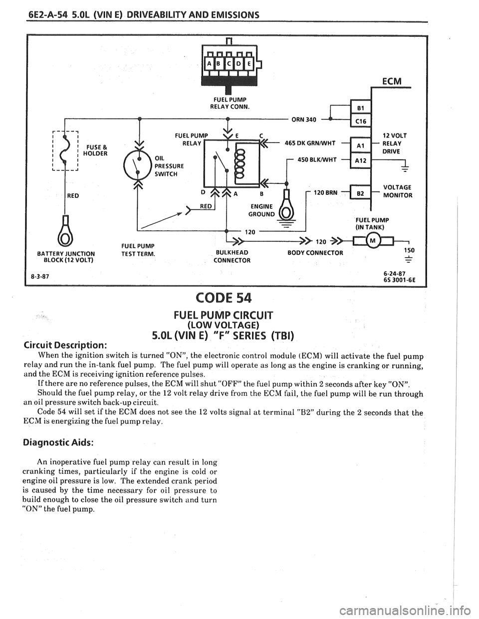
6E2-A-54 5.OL (VIN E) DRIVEABILITY AND EMISSIONS
465 DK GRNMlHT
450 BLWHT
FUEL PUMP BATTERY JUNCTION TEST TERM. BULKHEAD BODY CONNECTOR
BLOCK (12 VOLT) CONNECTOR
CODE 54
FUEL PUMP CIRCUIT
(LOW VOLTAGE)
5.OL (VIN E) "F"" SERIES (TBI)
Circuit Description:
When the ignition switch is turned "ON", the electronic control module (ECM) will activate the fuel pump
relay and run the in-tank fuel pump. The fuel pump will operate as long as the engine is cranking or running,
and the ECM is receiving ignition reference pulses.
If there are no reference pulses, the ECM will shut
"OFF" the fuel pump within 2 seconds after key "ON".
Should the fuel pump relay, or the
12 volt relay drive from the ECM fail, the fuel pump will be run through
an oil pressure switch back-up circuit.
Code
54 will set if the ECM does not see the 12 volts signal at terminal "B2" during the 2 seconds that the
ECM is energizing the fuel pump relay.
Diagnostic Aids:
An inoperative fuel pump relay can result in long
cranking times, particularly if the engine is cold or
engine oil pressure is low. The extended crank period
is caused by the time necessary for oil pressure to
build enough to close the oil pressure switch and turn
"ON" the fuel pump.
Page 549 of 1825
6EZ-B-2 5.OL (VIN E) DRIVEABILITY AND EMISSIONS
Problem may or may not turn "ON" the "Service Engine Soon" light, or store a code.
DO NOT use the trouble code charts in Section
"A" for intermittent problems. The fault must be
present to locate the problem. If a fault is
intermittent, use of trouble code charts may result
in replacement of good parts.
@ Most intermittent problems are caused by faulty
electrical connections or wiring. Perform
careful check of suspect circuits for:
- Poor mating of the connector halves, or
terminals, not fully seated in the connector
body (backed out).
I - Improperly formed or damaged terminals.
All connector terminals in problem circuit
should be carefully reformed to increase
contact tension.
- Poor terminal to wire connection. This
requires removing the terminal from the
connector body to check as outlined in the
Introduction to Section
"6E".
@ If a visual (physical) check does not find the
cause of the problem, the car can be driven with
a voltmeter connected to a suspected circuit or a
"Scan" tool may be used. An abnormal voltage
reading, when the problem occurs, indicates the
problem may be in that circuit. If the wiring
and connectors check OK, and a trouble code was
stored for a circuit having a sensor, except
for Codes 44 and 45, substitute a known good
sensor and recheck.
@ Loss of trouble code memory. To check,
disconnect TPS and idle engine until "Service
Engine Soon" light comes
"ON". Code 22 should
be stored, and kept in memory, when ignition is
turned "OFF" for at least 10 seconds. If not, the
ECM
is faulty.
@ An intermittent "SES" light, and no trouble
codes, may be caused by:
- Electrical system interference caused by a
defective relay, ECM driven solenoid, or switch.
They can cause a sharp electrical surge.
Normally, the problem will occur when the
faulty component is operated.
- Improper installation of electrical options, such
as lights, 2-way radios, etc.
- EST wires should be routed away from spark
plug wires, ignition system components, and
generator. Wire for CKT 453 from ECM to
ignition system should be a good ground.
- Ignition secondary shorted to ground.
- CKTs 419 ("SES" light) or 451 (Diagnostic Test)
intermittently shorted to ground.
- ECM power grounds.
HARD START
Definition: Engine cranks OK, but does not start for a long
time. Does eventually run, or may start but immediately dies.
, <
@ CHECK: 4. Connect a radiator test pump to the line and
- For water contaminated fuel. apply 103 kPa (15 psi) pressure. If the
- Fuel system pressure CHART A-7. pressure will hold for 60 seconds, the check
- TPS for sticking or binding should read less than
valve is OK.
1.25 volts on a "Scan" tool. @ Check ignition system for:
- No crank signal; see CHART C-1B. - Proper output with ST-125.
- EGR operation; CHART C-7. - Worn shaft.
- Fuel System - CHART A-7. - Rare and shorted wires.
- For a faulty in-tank fuel pump check valve, - Pickup coil resistance and connections.
which would allow the fuel in the lines to drain
- Loose ignition coil connections.
back to the tank after the engine is stopped. To
- Moisture in distributor cap.
check for this condition:
- Spark plugs, wet plugs, cracks, wear,
1. Ignition "OFF".
improper gap, burned electrodes, or heavy
2. Disconnect fuel line at the filter
deposits.
3. Remove the tank filler cap. @ If engine starts but then, immediately stalls,
open distributor bypass line. If engine then
starts, and runs OK, replace distributor pickup
coil.
@ Check CKT 423 (EST) for short to ground.
Page 553 of 1825
6E2-8-6 5.OL (VIN E) DRIVEABILITY AND EMISSIONS
- MAP Sensor - Ignition "ON", engine stopped.
Compare MAP voltage with known good vehicle.
-
Voltage should be the same + 400 mV (.4 volts).
OR
Start and idle engine. Disconnect
sensor
electrical connector. If idle improves, substitute
a known good sensor and recheck.
- A/C refrigerant pressure too high. Check for
overcharge or faulty pressure switch.
- PCV valve for proper operation by placing finger
over inlet hole in valve end several times. Valve
should snap back. If not, replace valve.
Run a cylinder compression check See Section
" 6".
Inspect oxygen sensor for silicon contamination
from fuel, or use of improper RTV sealant. The
sensor will have a white, powdery coating, and
will result in a high but false signal voltage (rich
exhaust indication). The ECM will then reduce
the amount of fuel delivered to the engine,
causing a severe driveability problem.
EXCESSIVE EXHAUST EMISSIONS OR ODORS
Definition: Vehicle fails an emission test. Vehicle has excessive "rotten egg"
smell. Excessive odors do not necessarily indicate excessive emissions.
@ Perform "Diagnostic Circuit Check".
@ IF TEST SHOWS EXCESSIVE CO AND HC, (or
also has excessive odors)
@ Check items that will cause engine to run
RICH.
e Make sure engine is at normal operating
temperature.
o CHECK:
- Fuel pressure. See CHART A-7.
- Incorrect timing. See Vehicle Emission
Control Information label.
- Canister for fuel loading. See CHART C-3.
- PCV valve for being plugged, stuck or blocked
PCV hose or fuel in the crankcase.
- Spark plugs, plug wires, and ignition
components. See Section
"6D".
- Check for lead contamination of catalytic
converter (look for removal of fuel filler neck
restrictor).
- Check for properly installed fuel cap.
@ If the system is running rich, (block learn less
than
1181, refer to "Diagnostic Aids" on facing
page of Code
45.
o IF TEST SHOWS EXCESSIVE NOx:
@ Check items which cause car to run LEAN, or
to run too hot.
- EGR valve for not opening. See CHART C-7.
- Vacuum leaks. - Coolant system and coolant fan for proper
operation. See
CHART C-12.
- Remove carbon with top engine cleaner.
Follow instructions on can.
- Check ignition timing for excessive base
advance. See Emission Control Information
label.
@ If the system is running lean, (block learn greater
than
138) refer to "Diagnostic Aids" on facing
page of Code
44.
DIESELING, RUN-ON
Definition: Engine continues to run after key is turned "OFF", but runs very roughly.
Ifengine runs smoothly, check ignition switch and adjustment.
@ Check injector for leaking. Apply 12 volts to fuel Visually check injector and TBI assembly for fuel
pump test terminal to turn "ON" fuel pump and leakage.
pressurize fuel system.
BACKFIRE
Definition: Fuel ignites in intake manifold, making a loud popping noise.
@ CHECK: - For faulty spark plugs and/or plug wires or
- EGR operation for being open all the time. See
hoots.
CHART C-7. - Faulty A.I.R. check valve.
- Output voltage of ignition coil. @ Perform a compression check - look for sticking or
- For crossfire between spark plugs (distributor leaking valves.
cap, spark plug wires, and proper routing' of plug
- For proper valve timing.
wires).
- Broken or worn valve train parts.
- Engine timing - See Emission Control
Information label.