1988 PONTIAC FIERO turn signal
[x] Cancel search: turn signalPage 171 of 1825
GENERAL MOTORS CORPORATION
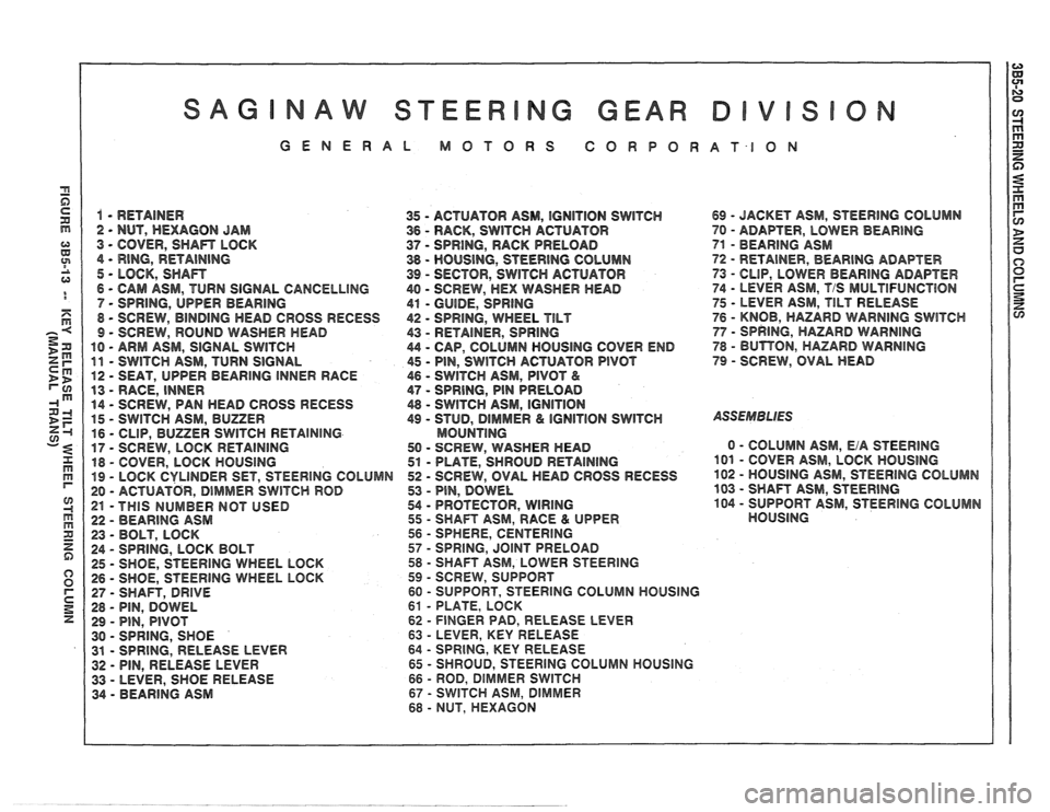
1 - RETAINER
35 - ACTUATOR ASM, IGNITION SWITCH 69 - JACKET ASM, STEERING COLUMN
2 - NUT, HEXAGON JAM
36 - RACK, SWITCH ACTUATOR 70 - ADAF"TER, LOWER BEARING
3 - COVER, SHAn LOCK 37 - SPRING, RACK PRELOAD 71 - BEARING ASM
4
- RING, RETAINING 38 - HOUSING, STEERING COLUMN 72 - RETAINER, BEAR1NG ADAPTER
5 - LOCK, SHAn 39 - SECTOR, SWITCH ACTUATOR
73 - CLIP, LOWER BEARING ADAPTER
6
- CAM ASM, TURN SIGNAL CANCELLING 40 - SCREW, HEX WASHER HEAD 74 - LEVER ASM, T/S MULTlFUNCTBON
7 - SPRING, UPPER
BEARING
41 - GUIDE, SPRING 75 - LEVER ASM, TILT RELEASE
8
- SCREW, BINDING HEAD CROSS RECESS 42 - SPRING, WHEEL TILT 76 - KNOB, HAZARD WARNING SWlTCH
9 - SCREW, ROUND WASHER MEAD
43 - RETAINER, SPRING 77 - SPRING, HAZARD WARNING
10 - ARM ASM, SIGNAL SWITCH 44 - CAP, COLUMN HOUSING COVER END 78 - BUTBON, HAZARD WARNING
11 - SWITCH
ASM, TURN SIGNAL 45 - PIN, SWITCH ACTUATOR PIVOT 79 - SCREW, OVAL HEAD
12
- SEAT, UPPER BEARING INNER RACE 46 - SWITCH ASM, PIVOT &
13 - RACE, INNER 47 - SPRING, PIN PRELOAD
14
- SCREW, PAN HEAD CROSS RECESS 48 - SWITCH ASM, IGNITION
15 - SWITCH
ASM, BUZZER 49 - STUD, DlMMER & IGNITION SWITCH ASSEMBLIES
16 - CLIP, BUZZER SWITCH RETAINING MOUNTlNG
17 - SCREW,
LOCK RETAINING 50 - SCREW, WASHER HEAD 0 - COLUMN
ASM, EiA STEERING
18
- COVER, LOCK HOUSING 51 - PLATE, SHROUD RETAINING 101 - COVER ASM, LOCK HOUSING
19 - LOCK CYLINDER SET, STEERING COLUMN 52 - SCREW,
OVAL HEAD GROSS RECESS 102 - HOUSING
ASM, STEERlNG COLUMN
20
- ACTUATOR, DIMMER SWITCH ROD 53 - PIN, DOWEL 103 - SHAFT
ASM, STEERING
21 -THIS NUMBER NOT USED 54 - PROTECTOR, WIRING
104 - SUPPORT
ASM, STEERING COLUMN
22
- BEARING ASM 55 - SHAFT
ASM, RACE & UPPER HOUSING
23
- BOLT, LOCK 56 - SPHERE,
CENTERING
24
- SPRING, LOCK BOLT 57 - SPRING, JOINT PRELOAD
25
- SHOE, STEERING WHEEL LOCK 58 - SHAFT ASM, LOWER STEERING
26 - SHOE, STEERING WHEEL LOCK 59 - SCREW,
SUPPORT
27
- SHAFT, DRIVE 60 - SUPPORT, STEERlNG COLUMN HOUSING
28
- PIN, DOWEL 61 - PLATE,
LOCK
29
- PIN, PIVOT 62 - FINGER PAD, RELEASE LEVER
30
- SPRING, SHOE 63 - LEVER, KEY RELEASE
31
- SPRING, RELEASE LEVER 64 - SPRING,
KEY RELEASE
32 - PIN, RELEASE LEVER 65 - SHROUD, STEERING COLUMN HOUSING
33
- LEVER, SHOE RELEASE 66 - ROD, DIMMER SWlTCH
34 - BEARING ASM 67 - SWITCH ASM, DlMrVlER
68 - NUT,
HEXAGON
Page 172 of 1825
STEERING WHEELS AND COLUMNS 385-21
SUB SECTION A
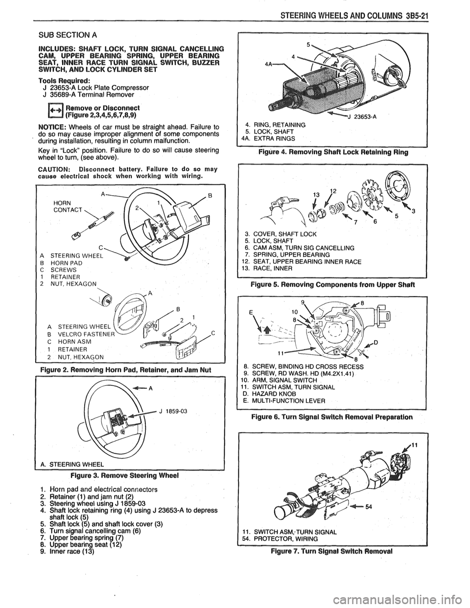
INCLUDES: SHAR LOCK, TURN SIGNAL CANCELLING
CAM, UPPER BEARING SPRING, UPPER BEARING
SEAT, INNER RACE TURN SIGNAL SWITCH,
BUZER SWITCH, AND LOCK CYLINDER SET
Tools
Requird: J 236534 Lock Plate Compressor J 35689-A Terminal Remover
Remove or Disconnect
(Flgure 2,3,4,5,5,7,8,9)
NOTICE: Wheels of car must be straight ahead. Failure to
do so may cause improper alignment of some components
' during installation, resulting in column malfunction.
Key in "Lock" position. Failure to do so will cause steering
wheel
to turn, (see above).
CAUTION: Disconnect battery. Failure to do so may cauee electrical shock when working with wiring.
A STEERING WHEEL B HORN PAD
C SCREWS
1 RETAINER
2 NUT, HEXAGON
B VELCRO FASTENER C HORNASM
1 RETAINER
Figure 2. Removing Horn Pad, Retainer, and Jam Nut
Figure 3. Remove
Stwring Wheel
1. Worn pad and electrical connectors 2. Retainer (1) and jam nut (2) 3. Steering wheel using J 1859-03 4. Shaft lock retaining ring (4) using J 23653-A to depress
shaft lock (5) 5. Shaft lock (5) and shaft lock cover (3) 6. Turn signal cancelling cam (6) 7. Upper bearing sprin (7) 8. Upper bearing seat 71 2)
9. inner race (1 3)
Figure 4. Removing Shafl hock Retaining Ring
3. COVER, SHAFT LOCK 5. LOCK, SHAFT 6. CAM ASM, TURN SIG CANCELLING 7. SPRING, UPPER BEARING 12. SEAT, UPPER BEARING INNER RACE 13. RACE, INNER
Figure 5. Removing Components from Upper Shafl
ROSSRECESS
Figure 6. Turn Signal Swltch Removal Preparation
Figure
7. Turn Signal Switch Removal
Page 173 of 1825
385-22 STEERING WHEELS AND COLUMNS
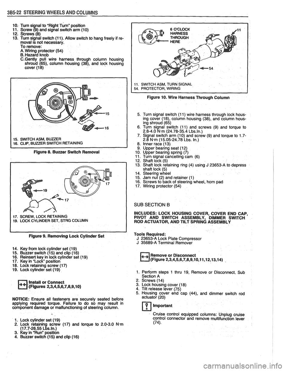
10. Turn si nal to "Right Turnn position 11. Screw f9) and signal switch arm (10) 12. crews (8) 13. Turn signal switch (11). Allow switch to hang freely if re- moval is not necessary.
To remove:
A. Wiring protector (54) B. Hanard knob C.Gently pull wire harness through column housing
shroud (65), column housing (38), and lock housing
cover (1 8)
5. Turn signal switch (I 1) wire harness through lock hous-
ing cover (18), column housing (38), and column hous-
ing shroud (65)
6. Turn signal switch (1 1) and screws (9) and torque to
2.8-4.0
N.m (24.78-35.4 Lbs.ln.) 7. Signal switch arm (10) and screw (9) and torque to 1.7- 2.8 N.m (1 5.05-24.78 Lbs. In.)
8. Inner race (13)
9. Upper bearing seat (12)
10. Upper bearing spring (7)
11. Turn signal cancelling cam (6)
12. Shaft lock (5)
13. Shaft lock retaining ring (4) using J 23653-A to depress
shaft lock (5)
14. Steering wheel
15. Jam nut (2) and retainer
(1) 16. Screws to back of steering wheel, horn pad
17. Wiring protector (54)
SUB SECTION 6
17. SCREW, LOCK RETAINING INCLUDES:
LOCK HOUSING COVER, COVER END CAP, 19. LOCK CYLINDER SET, STRG COLUMN PIVOT
AND SWITCH ASSEMBLY, DIMMER SWITCH
ROD ACTUATOR, AND TILT SPRING ASSEMBLY
Flgurs 9. Rsmovlng Lock Cylinder Set Tools
Required:
J 23653-A Lock Plate Compressor
J 35689-A Terminal Remover
14. Key from lock cylinder set (19)
15.
Buuer switch (1 5) and clip (1 6)
16. Reinsert key in lock cylinder set (1 9) Remove
or Disconnect
17. Key in "Lock" position
m(Flgure 2,3,4,5,6,7,8,9,10,11,12,13,14) -
18. Lock retaining screw (1 7) 19. Lock cylinder set (1 9) 1. Perform steps 1 thru 19, Remove or Disconnect, Sub
Section A
lnsbll or Connect 2.
Screws (14)
m~(FIguns 2,3,4,56,7,(1,9,10) 3. Lock housing cover (1 8)
4. Tilt release lever (75)
5. Housing cover end cap
(44), and dimmer switch rod
NOTICE: Ensure all fasteners are securely seated before actuator (20)
applying required torque. Failure to do so may result in
component damage or malfunctioning of steering column.
lmporlant
Cruise control equipped columns: Unplug cruise
1. Lock cylinder set
(1 9) control
connector and remove multifunction lever 2. Lock retainin screw (17) and torque to 2.0-3.0 N-m (74).
(1 7.7-2~55 ~!s.ln.) 3. Key in "Runn position 4. Buner switch (1 5) and clip (1 6)
Page 179 of 1825
NAW STEER NG GEAR
GENERAL MOTORS CORBOR
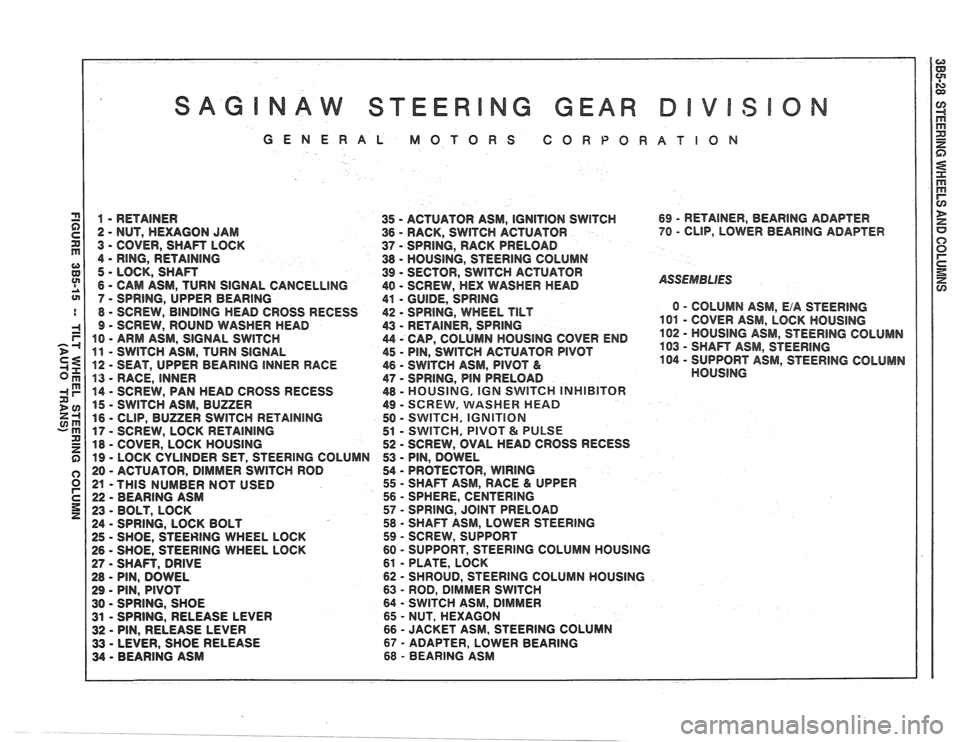
1 - RETAINER
35 - ACTUATOR ASM, IGNlTlON SWITCH
2
- NUT, HEXAGON JAM 36 - RACK, SWITCH ACTUATOR
3
- COVER, SHAFT LOCK
37 - SPRING, RACK PRELOAD
4
- RING, RETAINING 38 - HOUSING, STEERING COLUMN
5
- LOCK, SHAFT
39 - SECTOR, SWITCH ACTUATOR
6
- CAM ASM, TURN SIGNAL CANCELLING 40 - SCREW, HEX WASHER HEAD
7
- SPRING, UPPER BEARING
41 - GUIDE, SPRING
8 - SCREW, BINDING HEAD CROSS RECESS 42 - SPRING, WHEEL TILT
9 - SCREW, ROUND WASHER HEAD
43 - RETAINER, SPRING
10
- ARM ASM, SIGNAL SWITCH 44 - CAP, COLUMN HOUSING COVER END
11 - SWlTCH ASM, TURN SIGNAL 45 - PIN, SWlTCH ACTUATOR PIVOT
12 - SEAT, UPPER BEARING INNER RACE
46 - SWITCH ASM, PIVOT &
13 - RACE, INNER 47 - SPRING, PIN PRELOAD
14
- SCREW, PAN HEAD CROSS RECESS 48 - MOUSING,
IGN SWITCH INHIBITOR
15 - SWITCH ASM, BUZZER 49 - SCREVV, VVASHER MEAD
16
- CLIP, BUZZER SWITCH RETAINING 50 - SWITCH, IGNITION
17 - SCREW,
LOCK RETAINING 51 - SWITCH, PIVOT & PULSE
18
- COVER, LOCK HOUSING 52 - SCREW,
OVAL HEAD CROSS RECESS
19
- LOCK CYLINDER SET, STEERING COLUMN 53 - PIN, DOWEL
20
- ACTUATOR, DIMMER SWITCH ROD 54 - PROTECTOR, WlRlNG
21 -THIS
NUMBER NOT USED 55 - SHAFT
ASM, RACE & UPPER
22
- BEARING ASM 56 - SPHERE,
CENTERING
23
- BOLT, LOCK 57 - SPRING,
JOINT PRELOAD
24
- SPRING, LOCK BOLT 58 - SHAFT ASM, LOWER STEERING
25
- SHOE, STEERING WHEEL LOCK 59 - SCREW,
SUPPORT
1 26 - SHOE, STEERING WHEEL LOCK 60 - SUPPORT,
STEERING COLUMN HOUSING
27
- SHAR, DRIVE 61 - PLATE, LOCK
28
- PIN, DOWEL 62 - SHROUD,
STEERING COLUMN HOUSING
29
- PIN, PIVOT 63 - ROD,
DIMMER SWITCH
30
- SPRING, SHOE 64 - SWITCH
ASM, DIMMER
31
- SPRING, RELEASE LEVER 65 - NUT,
HEXAGON
32
- PIN, RELEASE LEVER 66 - JACKET
ASM, STEERING COLUMN
33
- LEVER, SHOE RELEASE 67 - ADAPTER, LOWER BEARING
34
- BEARING ASM 68 - BEARING
ASM 69
- RETAINER,
BEARlNG ADAPTER
70
- CLIP, LOWER BEARING ADAPTER
ASSEMBLIES
0 - COLUMN ASM, E/A STEERING
101 - COVER ASM, LOCK HOUSlNG
102
- HOUSING ASM, STEERlNG COLUMN
103
- SHAFT ASM, STEERING
104 - SUPPORT ASM, STEERlNG COLUMN
HOUSlNG
Page 180 of 1825
STEERING WHEELS AND COLUMNS 3B5-29
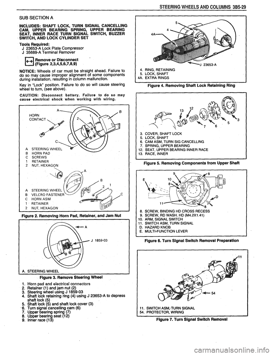
SUB SECTION A
INCLUDES: SHAm LOCK, TURN SIGNAL CANCELLlNG CAM, UPPER BEARING SPRING, UPPER BEARING
SEAT, INNER RACE TURN SIGNAL SWITCH, BUZZER
SWITCH,
AND LOCK CYLINDER SET
Tools
Requird: J 23653-A Lock Plate Compressor J 35689-A Terminal Remover
Remove or Disconnect
(Figure
,2,3,4,5,6,7,8,9)
NOTICE: Wheels of car must be straight ahead. Failure to
do so may cause improper alignment of some components
during installation, resulting in column malfunction.
Key in
"Lock position. Failure to do so will cause steering
wheel to turn, (see above).
CAUTION: Disconnect battery. Failure to do so may
cause electrical shock when working with wiring.
HORN '. 72' CONTACT
A STEERING WHEEL
B HORN PAD C SCREWS 1 RETAINER 2 NUT, HEXAGON
A STEERING WHEEL
B VELCRO FASTENER C HORNASM
1 RETAINER
2 NUT, HEXAGON L!lY -
Figure 2. Removing Horn Pad, Retainer, and Jam Nut
Figure 3. Remove
Stwring Wheel
1. Horn pad and electrical connectors
2. Retainer (1) and jam nut (2) 3. Steering wheel using J 1859-03
4. Shaft lock retaining ring (4) using J 23653-A to depress
shaft lock (5)
5. Shaft lock (5) and shaft lock cover (3)
6. Turn signal cancelling cam (6)
7. Upper bearing sprin (7) 8. Upper bearing seat R 2) 9. Inner race (13)
4. RING, RETAINING
5. LOCK, SHAFT
4A. EXTRA RINGS
Figure 4. Removing Shafl Lock Retaining Ring
3. COVER, SHAm LOCK 5. LOCK, SHAFT 6. CAM ASM, TURN SIG CANCELLING 7. SPRING, UPPER BEARING
12. SEAT, UPPER BEARING INNER RACE
13. RACE, INNER
Figure 5. Removing Components from Upper Shan
Figure 6. Turn Signal Swltch Removal Preparation
11. SWITCH ASM;TURN SIGNAL 54. PROTECTOR, WIRING
Flgure 7. Turn Signal Switch Removal
Page 181 of 1825
385-30 STEERING WHEELS AND COLUMNS
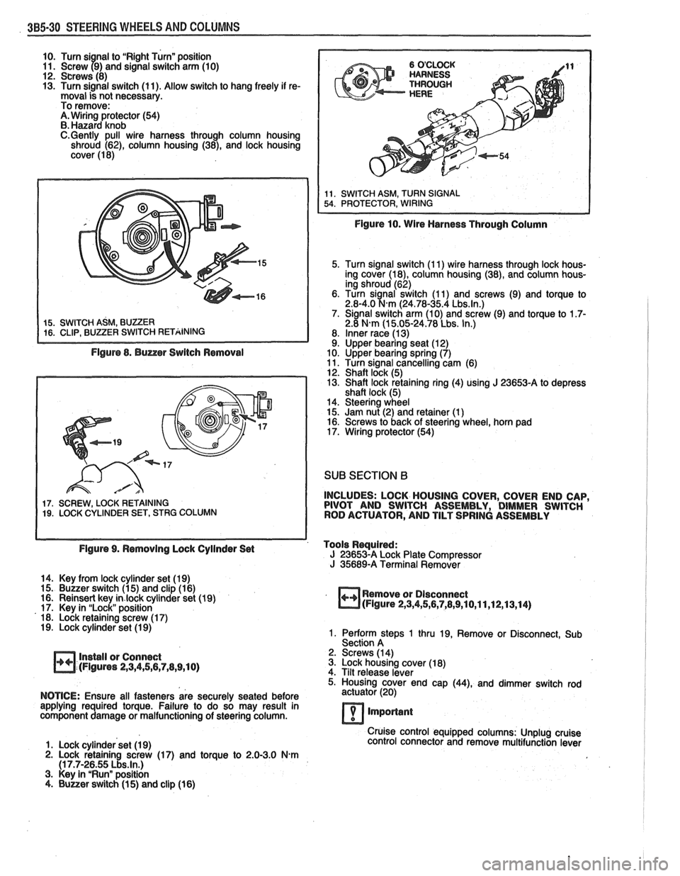
10. Turn si nal to "Right Turn" position
11. Screw 79) and signal switch arm (10)
12. Screws (8)
13. Turn signal switch (11). Allow switch to hang freely if re-
moval is not necessary.
To remove:
A. Wiring protector (54)
B. Hazard knob
C.Gently pull wire harness through column housing
shroud (62), column housing (38), and lock housing
cover (1 8)
Figure 8. Buzzer Switch Removal
17. SCREW, LOCK RETAINING 19. LOCK CYLINDER SET, STRG COLUMN
Figure 10. Wire Harness Through Column
5. Turn signal switch (1 1) wire harness through lock hous-
ing cover
(la), column housing (38), and column hous-
ing shroud (62)
6. Turn
sianal switch (1 1) and screws (9) and torque to 2.8-4.0 %km (24.78-35.4 Lbs.ln.) 7. Signal switch arm (10) and screw (9) and torque to 1.7- 2.8 N-m (1 5.05-24.78 Lbs. In.)
8. Inner race (1 3) 9. Upper bearing seat (1 2)
10. Upper bearing spring (7)
11. Turn signal cancelling cam (6)
12. Shaft lock (5)
13. Shaft lock retaining ring (4) using
J 23653-A to depress
shaft lock (5)
14. Steering wheel
15. Jam nut (2) and retainer (1
) 16. Screws to back of steering wheel, horn pad
17. Wiring protector (54)
SUB SECTION B
INCLUDES: LOCK HOUSING COVER, COVER END CAP,
PIVOT AND SWITCH ASSEMBLY, DIMMER SWITCH
ROD ACTUATOR, AND TILT SPRING ASSEMBLY
Figure 9. Removing Lock Cyilnder Set Tools
Rwuired: J 23653-A Lock
Plate Compressor J 35689-A Terminal Remover
14. Key from lock cylinder set (19)
15. Buzzer switch (1 5) and clip (1 6)
16. Reinsert key
in.lock cylinder set (19)
17. Key in "Lock" position
18. Lock retaining screw (1 7)
19. Lock cylinder set (1 9)
Install or Connect
(Figures
2,3,4,5,6,7,8,9,10)
Remove or Dlsconnect (Figure 2,3,4,5,6,7,8,9,10,11,12,13,14)
1. Perform steps 1 thru 19, Remove or Disconnect, Sub
Section A
2. Screws (1 4)
3. Lock housing cover (1 8)
4. Tilt release lever
5. Housing cover end cap
(44), and dimmer switch rod
NOTICE: Ensure all fasteners are securely seated before actuator
(20)
applying required torque. Failure to do so may result in
component damage or malfunctioning of steering column.
7 important
Cruise control equipped columns: Unplug cruise
1. Lock cylinder set (1 9) control
connector and remove multifunction lever
2. Lock retaining screw (17) and torque to 2.0-3.0 N.m (1 7.7-26.55 Lbs.ln.) 3. Key in "Run" position
4. Buuer switch (1 5) and clip (16)
Page 186 of 1825
STEERING WHEELS AND COLUMNS 385.35
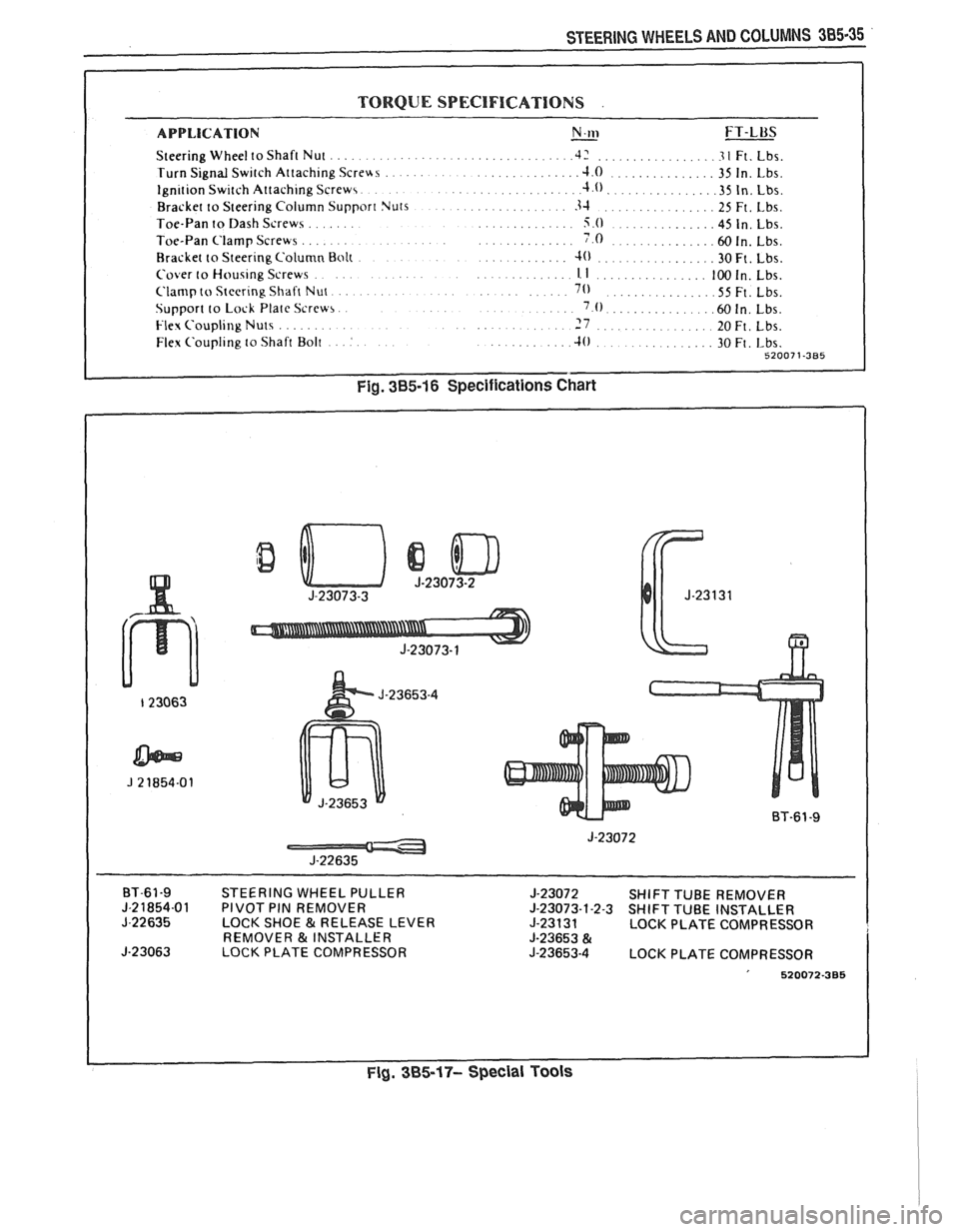
TORQUE SPECIFICATIONS .
APPLICATION N.w - FT-LUS
Steering Wheel to Shaft Nut .................................. .42 ................ .3 1 Ft. Lbs.
Turn Signal Switch Attaching
Screus ...................... .J.O ............... 35 In. Lbs.
.. Ignition Switch Attaching Screws. ................. .4.0.. ............. .35 In. Lbs.
Bracket to Steering Column Support Nuts
................. 3-1 ................ 25 Ft. Lbs.
....... Toe-Pan to Dash Screws .............. 5.0 .............. 45 In. Lbs.
....... .............. Toe-Pan Clamp Screws ..... 7.0 .............. .60 In. Lbs.
Bracket to Steering Column Bolt
............. 4) ................. 30Ft. Lbs.
.... Cover to Housing Screws . ,. . .............. 1. I ................ 100 In. Lbs.
..... Clamp to Steering Shaft Nut. ............. 70 ............... .55 Ft. Lbs.
Support to Lock Plate Screw,.
. . . ..... '.0. .............. ,150 In. Lbs.
......... Flex Coupling Nuts ........... 7 ................. 20~t. ~bs.
... Flex Coupling to Shaft Bolt : .......... .10 30 Ft, ~bs. .............. 52007 1-385
Fig. 385-16 Specifications Chart
BT-61-9 STEERING WHEEL PULLER
J-23072 SHIFT TUBE REMOVER J-21854-01 PIVOT PIN REMOVER J-23073-1-2-3 SHIFT TUBE INSTALLER
J-22635 LOCK SHOE & RELEASE LEVER
J-23131 LOCK PLATE COMPRESSOR
REMOVER & INSTALLER J-23653 & J-23063 LOCK PLATE COMPRESSOR J-23653-4 LOCK PLATE COMPRESSOR
' 520072-385
Fig. 385-17- Special Tools
Page 434 of 1825
ENGINE FUEL 6C.3
a Fuel feed and return pipes are secured to the
underbody with clamps and screw assemblies.
The pipes should be inspected occasionally for
leaks, kinks or dents.
e Follow the same routing as the original pipe.
e Pipes must be properly secured to the frame to
prevent chafing. A minimum of 6 mm
(1/4")
clearance must be maintained around a pipe to
prevent contact and chafing.
MPFl Fuel Pipes
Due to the fact that fuel pipes are under high
pressure, these systems require special consideration for service.
Many feed and return pipes use screw couplings
with
"0" Rings. Any time these fittings are loosened
to service or replace components, ensure that:
a A backup wrench is used while loosening and
tightening the fitting.
e Check all "0" rings at fitting locations (if
applicable) for cuts or any damage and replace
any that appear worn or damaged.
e Use correct torque when tightening fittings.
If pipes are replaced always use original
equipment parts, or parts that meet GM
specifications.
Fuel and Vapor Hoses
NOTICE: Fuel and vapor hoses are specially
manufactured. If replacement becomes necessary,
it is important to use only replacement hoses
meeting GM Specification 6163-M. These hoses
are identified with the words "Fluoroelastomer"
on them. Hoses not so marked could cause early
failure, or fail to meet emission standards.
e Do not use rubber hose within 4" of any part of
the exhaust system, or within
10" of the catalytic
converter.
FUEL PUMP
The electric fuel pump is in the fuel tank. The
tank has an outlet for a vapor return system. Any vapor
which forms is returned to the fuel tank along with hot
fuel through a separate line. This greatly reduces any
possibility of vapor lock by keeping cool fuel from the
tank constantly circulating through the fuel pump.
FUEL PUMP RELAY
To control fuel pump operation, a fuel pump
relay is used.
When the ignition switch is turned to "RUN"
position, the fuel pump relay activates the electric fuel
pump for
1.5 to 2.0 seconds to prime the injector(s). If
the ECM does not receive reference pulses from the
distributor after this time, the ECM signals the relay
to turn off the fuel pump. The relay will once again
activate the fuel pump when the
ECM receives
distributor reference pulses.
Fuel Filter
CAUTION: To reduce the risk of fire
and personal injury, it is necessary
to
relieve the fuel system pressure
before servicing fuel system
components. (See Fuel System
Pressure Relief.)
The inline filters can be found on the rear
crossmember of the vehicle. Always use a backup
wrench any time that the fuel filter is removed or
installed. Also make sure that a good
"0" Ring is used
at all screw couple locations. Torque on fittings is
30
N-m (22 lb. ft.).
FUEL TANK
The fuel tank is usually located under the rear of
the vehicle and a number of shapes and sizes are used
depending on the application.
The tank is held in place by two metal straps,
hinged (with a bolt through the hinge) and secured at
the opposite end with a nut and bolt assembly.
Anti-squeak pieces are used on top of the tank to
reduce rattles and other annoying noises.
The fuel tank, cap and lines should be inspected
for road damage, whch could cause leakage. Inspect
fuel cap for correct sealing and indications of physical
damage. Replace any damaged or malfunctioning
parts.
Before attempting service of any type on the fuel
tank, always
(1) remove negative battery cable from
battery, (2) place "no smoking" signs near work areas,
(3) be sure to have C02 fire extinguisher handy, (4)
wear safety glasses and
(5) siphon or pump fuel into an
explosion proof container.
Fuel Filler Gap
The fuel tank filler neck is equipped with a
screw-type cap. The threaded part of the cap requires
several turns counterclockwise to remove. The long
threaded area is designed to allow any remaining fuel
tank pressure to escape while the cap is being removed.
A built-in torque-limiting device prevents
overtightening. To install, turn the cap clockwise until
a clicking noise is heard. This signals that the correct
torque has been reached and the cap is fully seated.
N OTI G E: If a fuel filler cap requires replacement,
use only a cap with the same features. Failure to
use the correct cap can result in a serious
malfunction of the system.
Available on some models is an electric locking
fuel filler cap. Information on this option will be found
in Section
9E.
FUEL TANK FILLER NECK
To help prevent refueling with leaded gasoline,
the fuel filler neck on gasoline engine cars has a built-in
restrictor and deflector. The opening in the restrictor
will only admit the smaller unleaded gas nozzle spout,
which must be fully inserted to bypass the deflector.
Attempted refueling with a leaded gas nozzle or failure