1988 PONTIAC FIERO turn signal
[x] Cancel search: turn signalPage 787 of 1825
6E3-C8-2 2.8L (VIN S) DRIVEABILITY AND EMISSIONS
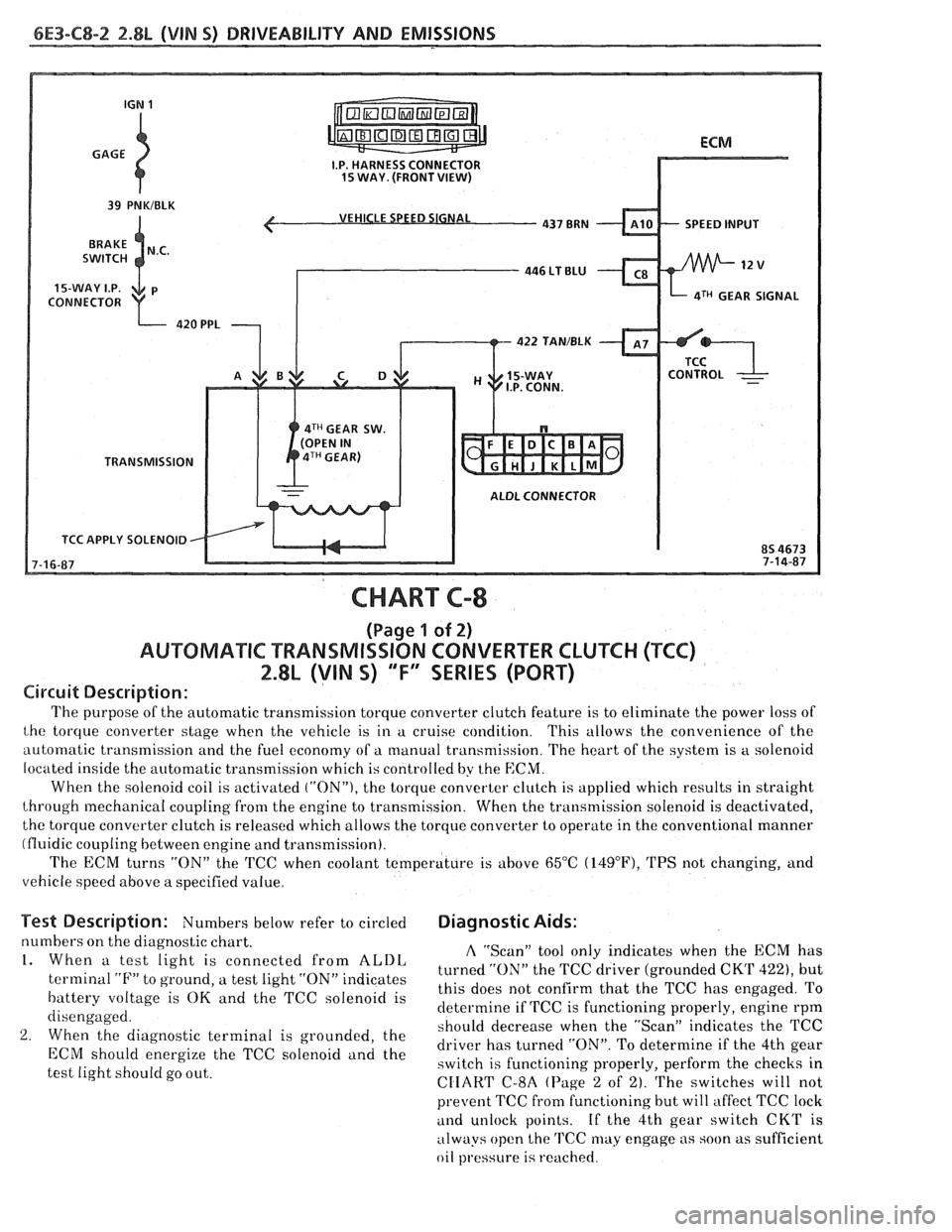
VEHICLE SPEED SIGNAL
SPEED INPUT
CONNECTOR
aTH GEAR SIGNAL
422 TAN/BLK
4TH GEAR SW.
TRANSMISSION
ALDL CONNECTOR
TCC APPLY SOLENOID
CHART C-8
(Page 1 of 2)
AUWBMATIC TRANSMISSION CONVERTER CLUTCH (TCC)
2.8L (VIN S) "F" SERIES (PORT)
Circuit Description:
The purpose of the automatic transmission torque converter clutch feature is to eliminate the power loss of
the torque converter stage when the vehicle is in a cruise condition. This allows the convenience of the
automatic transmission and the fuel economy of a manual transmission. The heart of the system is
a solenoid
located inside the automatic transmission which is controlled by the
ECM.
When the solenoid coil is activated ("ON"), the torque converter clutch is applied which results in straight
through mechanical coupling from the engine to transmission. When the transmission solenoid is deactivated,
the torque converter clutch is released which allows the torque converter to operate in the conventional manner
(fluidic coupling between engine and transmission).
The ECM turns
"ON" the 'KC when coolant temperature is above 65°C (14g°F), TPS not changing, and
vehicle speed above a specified value.
Test Description: Numbers below refer to circled Diagnostic Aids:
numbers on the diagnostic chart. A "Scan" tool only indicates when the ECM has 1. When a test light is connected from ALDL turned the TCC driver (grounded CKT 422), but terminal "F" to ground, a test light "ON" indicates
this does not confirm that the TCC has engaged. To battery voltage is OK and the TCC solenoid is
determine if TCC is functioning properly, engine rpm
disengaged.
should decrease when the "ScanJ' indicates the TCC
2. When the diagnostic terminal is grounded, the
driver has turned "ON". To determine if the 4th gear ECM energize the TCC "Ienoid and the switch is functioning properly, perform the checks in
test light should go out.
CIIART C-8A (Page 2 of 2). The switches will not
prevent TCC fi-om functioning but will affect TCC lock
and unlock points. If the 4th gear switch CKT is
always open the
TCC may engage as soon as sufficient
oil
pl.essure is reached.
Page 789 of 1825
6E3-C8-4 2.8L (VIN 5) DRIVEABILITY AND EMISSIONS
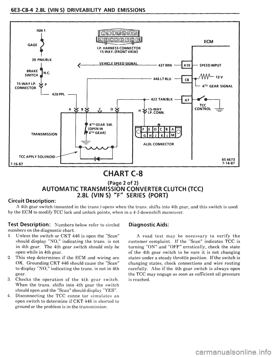
VEHICLE SPEED SIGNAL
4TH GEAR SIGNAL
422 TANIBLK
4TH GEAR SW.
TRANSMISSION
ALDL CONNECTOR
TCC APPLY SOLENOID
CHART C-8
(Page 2 of 2)
AUTOMATIC TRANSMISSION CONVERTER CLUTCH (TCC)
2.8L (VIN S) "F" SERIES (PORT)
Circuit Description:
A 4th gear switch (mounted in the trans.) opens when the trans. shifts into 4th gear, and this switch is used
by the ECM to modify TCC lock and unlock points, when in
a 4-3 downshift maneuver.
Test Description: Numbers I~elow refer to circled
numbers on the diagnostic chart.
1. Unless the switch or CKT 446 is open the "Scan"
should display "NO," indicating the trans. is not
in 4th gear. The 4th gear switch should only be
open while in 4th gear.
2. This step determines if the ECM and wiring are
OK. Grounding CKT 446 should cause the "Scan"
to display "NO," indicating the trans. is not in 4th
gear.
3. Checks the operation of the 4th gear switch.
When the trans. shifts into 4th gear the switch
should open and the "Scan" should display "YES".
4. Disconnecting the
'FCC conne tor sinlulates an
open switch to determine if CKT 446
is shorted to
ground or the problem is in the transmission.
Diagnostic Aids:
A road test may he necessary to verify the
customer complaint. If the "Scan" indicates TCC is
turning
"ON" and "OFF" erratically, check the state
of the 4th gear switch
to be sure it is not changing
states under a steady throttle position. If the switch is
changing states, check connections and wire routing
carefully.
Also if the 4th gear switch is always open
the
'FCC may engage as soon as sufficient oil pressure
is reached.
Page 793 of 1825
6E3-C10-2 2.8L (VIN S) DRIVEABILITY AND EMISSIONS
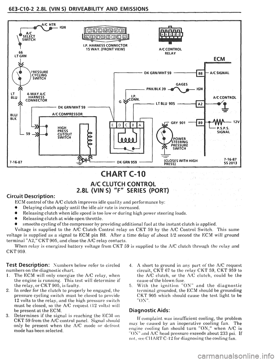
A/C CONTROL
DK GRNNVHT 59
CHART C-10
AIC CLUTCH CONTROL
2.8L (VIN S) "F" WRIES (PORT)
Circuit Description:
ECM control of the A/C clutch improves idle quality and performance by:
Delaying clutch apply
until the idle air rate is increased.
e Releasing clutch when idle speed is too low or during high power steering loilds.
e Releasing clutch a1 wide open throttle.
smooths cyclingof the compressor by providing additional fuel at the instant clutch
is applied.
Voltage is supplied to the
NC Clutch Control relay on CKT 59 by the NC Control Switch. This saine
voltage is supplied as a signal to ECM pit1 88. After a time delay of about 112 second the ECM twill ground
terminal
"A2," CKT 905, and close the A/C relay contacts.
When
relay is energi~etf battery vollage from CKT 59 is supplied to the IVC clulch lhroug11 Ihe txlay arid
CKT 959.
Test Description: Numbers below refer to circled
numbers on the diagnostic chart.
1. The ECM will only energize the A/C relay, when
the engine is running.
'I'his lest will determine if
the relay, or CK'F 905, is Sauity.
2. In order for the clutch to proper1.y be engaged, the
pressure cycling switch must bc closc!cl to provide
12 volts to the relay,
ilnd the high pressure switch
must be closed, so the
AlC rtquest (12 volts) wlll
be present at the ECNI.
3. Determines if the signal is ~.eachitlg the I4:CAI on
CKT 59 from the A/C control panel. Signal hhoitld
only be present when the AlC mode or tlcl'rost
mode has been selected.
4. A short to ground in any part ot' the A/C request
circuit, CKT
67 to the relay CKrI' 59, CKT 959 to
the NC clutch, or the
:2/C clutch, coulcl be the
cause
ofthe blown fiise.
5. With the ignition "ON" and the diagnostic
tcrminal grounded, the ECM should be grounding
CKT 905 which should cause the test light to be
"ON".
Diagnostic Aids:
If complaint was insufficient cooling, the problem
111~1,~ be ciiuscd by an inoperalive cooling fan. 'I'he
t!11gine cooling fan should turn "ON," when AlC is
"ON" ,tntl cZ/C head pressure exceeds about 233 psi. If
not. qctt: ("I Iclli'I' C-12 for diagnosing the cooling fan.
Page 796 of 1825
DRIVEABILITY AND EMISSIONS 2.8L (VIN S) 6E3-C12-1
SECTION C12
COOLING FAN CONTROL
CONTENTS
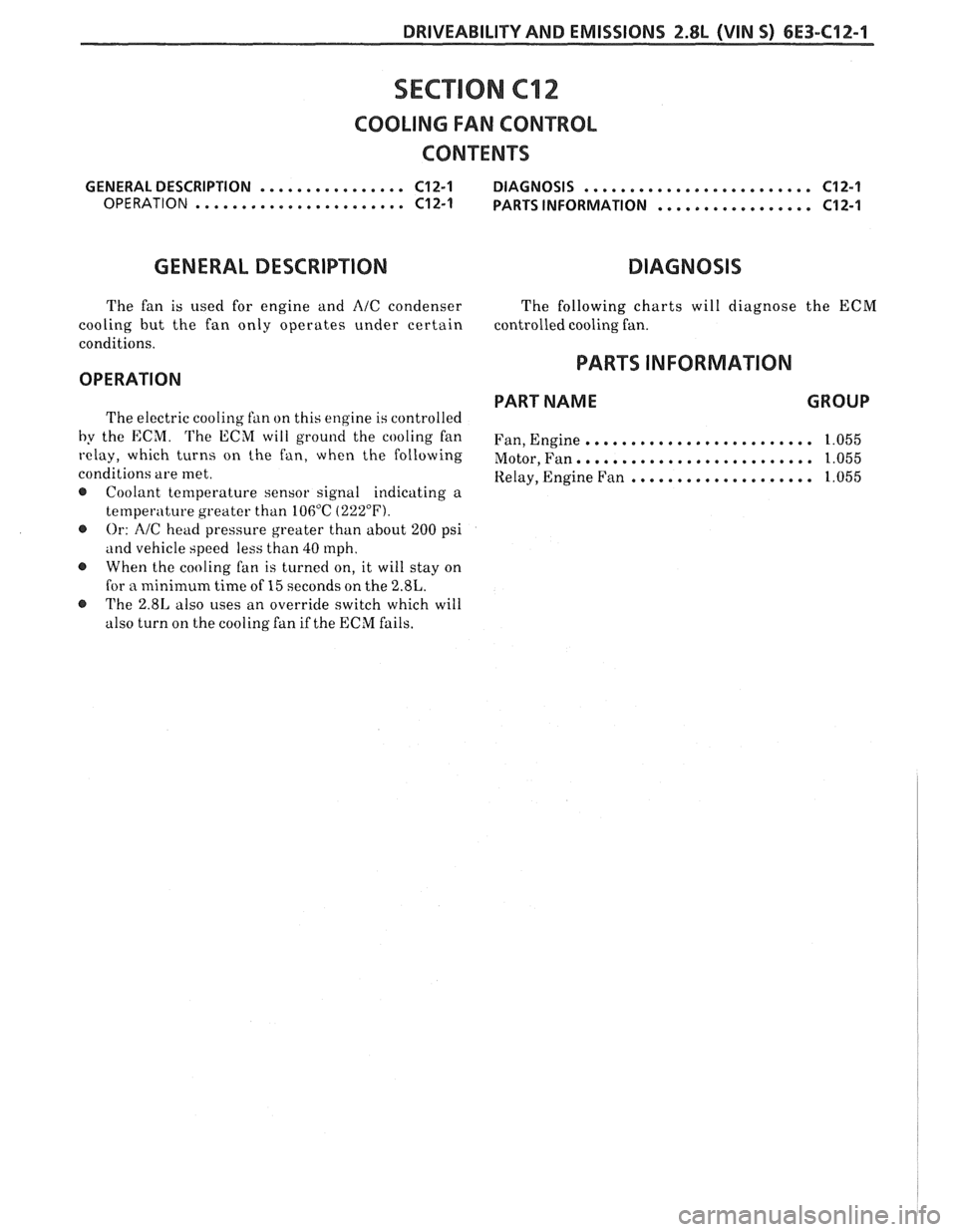
GENERAL DESCRIPTION ................ C12-1 DIAGNOSIS ......................... C12-1
OPERATION ....................... C12-1 PARTS INFORMATION ................. C12-1
GENERAL DESCRIPTION DIAGNOSIS
The fan is used for engine and A/C condenser The following charts will diagnose the ECM
cooling but the fan only operates under certain controlledcoolingfan.
conditions.
PARTS INFORMATION OPERATION
PART NAME
GROUP The electric cooling fan on this engine is controlled
by the ECM. The ECM will ground the cooling fan Fan, Enginee.. ...................... 1.055
relay, which turns on the fan, when the following Motor,Fan.. .~~...~~~.~~~~.~~....~.. 1.055
conditions are met. Kelay, Engine Fan .................... 1.055
@ Coolant temperature sensor signal indicating a
temperature greater than 106°C (222°F).
@ Or: A/C head pressure greater than about 200 psi
and vehicle speed less than 40 tnph.
When the cooling fan is turned on, it will stay on
for
a minimum time of 15 seconds on the 2.8L.
@ The 2.81, also uses an override switch which will
also turn
on the cooling fan if the ECM fails.
Page 797 of 1825
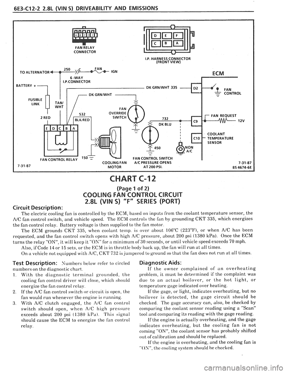
CONNECTOR
TO ALTERNATOR
I.P.CONNECTOR
DK GRNNVHT 335
CHART C-12
(Page 1 of 2)
COOLING FAN CONTROL CIRCUIT
2.8L (VIN S) "F" SERIES (PORT)
Circuit Description:
'I'he electric cooling fan is controlled by the ECM, based on inputs from the coolant temperature sensor, the
NC fan control switch, and vehicle speed. 'I'he ECM controls the f~in by grounding CKT 335, which energizes
the fan control relay. Battery voltage is then supplied to the fan motor.
The ECM grounds
CKT 335, when coolant temp. is over about 106°C (223"F), or when AIC has been
requested, and the fan control switch opens with high
I\/C pressure, about 200 psi (1380 kPa). Once the ECM
turns the relay "ON", it will keep it "ON" for a nlinirnum of GO seconds, or until vehicle speed exceeds 70 mph.
Also, if Code
14 or 15 sets, or the ECM is in throttle body back up, the fan will run at all times.
On
kt vehicle not equipped with A/C, CK'I' 732 is,ju~rlperetl to ground so that Lhe fan does not run at all times.
Test Description: Numbers below refer to circled
numbers on the diagnostic chart,.
1. With the diagnostic terminal grounded, the
cooling
fan control driver will close, which should
energize the fan control
relay.
2. If the A/C fan control switch or circuit is open, the
fan would run whenever the engine is running.
3. With AIC clutch engaged, the i\lC fan control
switch should open, when
A/C high pressure
exceeds about
200 psi ( 1380 k13a). This signal
should cause the
ECM to energize the ran control
relay.
Diagnostic Aids:
If the owner complained of an overheating
problem, it
rnust he determined if the complaint was
clue to an actuill hoilover, or the hot light, or
temperature gage indicated over heating.
If the gage, or light, indicates overheating, but no
hoilover is detected, the gage circuit should he
checked.
'I'he gage accuracy can, also, be checked by
comparing the coolant sensor reading using a "Scan"
tool and comparing its reading with the gage reading.
If the engine is actually overheating, and the gage
indicates overheating, but the cooling fan is not
coming "ON", the coolant sensor has probably shifted
out
ofcalibration and should be replaced.
If
the engine is overheating, and the cooling fan is
"ON", the cooling system should hc checked.
Page 806 of 1825
DRIVEABILITY AND EMISSIONS 5.OL (VIN F) & 5.7L (VIN 8) 6E3-A-3
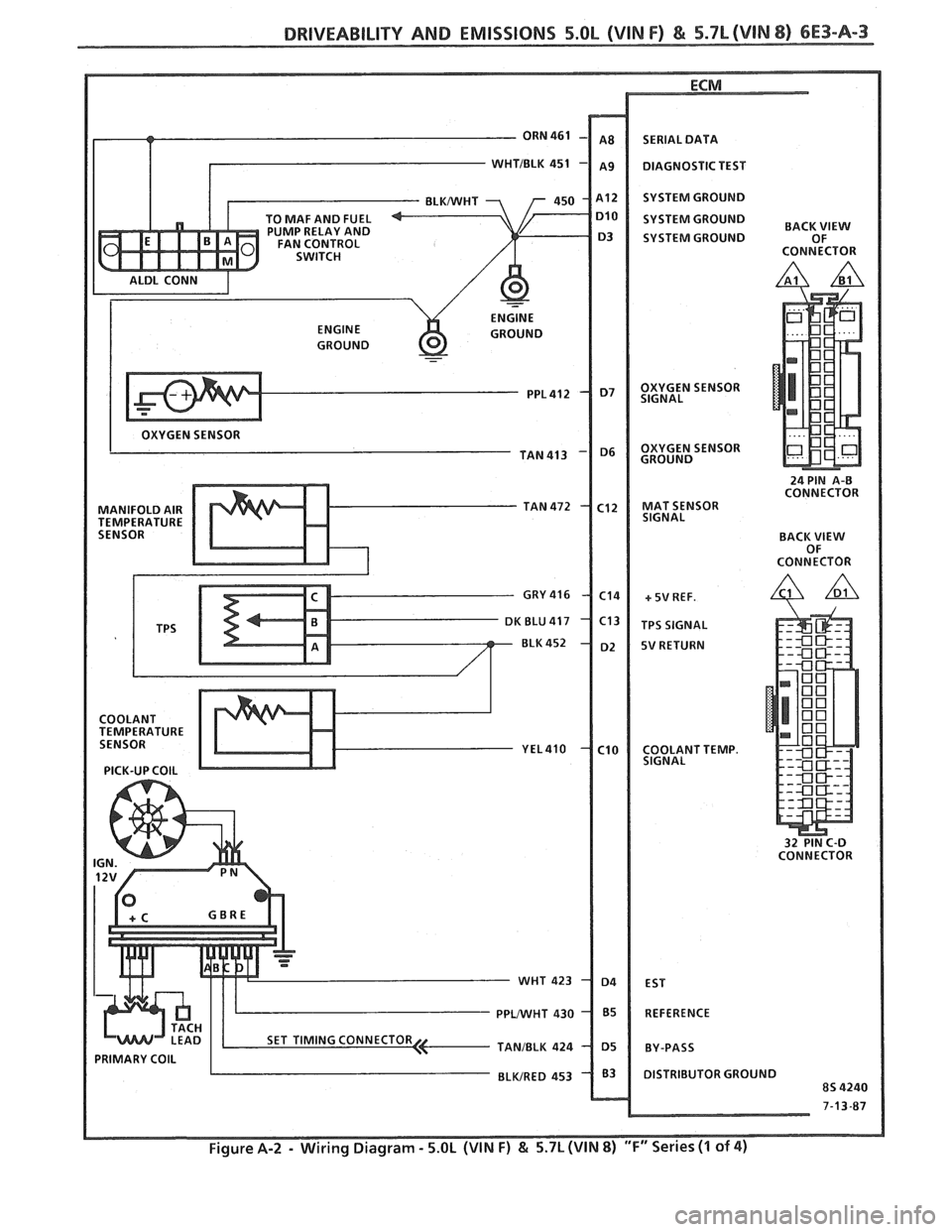
- ORN 461
T
TO MAF AND FUEL
PUMP RELAY AND
FAN CONTROL
SWITCH
ALDL CONN
I ENGINE
ENGINE GROUND
GROUND
-
OXYGEN SENSOR
TAN 413
MANIFOLD AIR TAN 472
TEMPERATURE SENSOR
GRY
416
K BLU 417
BLK 452
COOLANT
TEMPERATURE
SENSOR
YEL4lO
PICK-UP COlL
PRIMARY COlL I ..
- WHT
PPWHT
TANJBLK
BLWRED SERIAL
DATA
DIAGNOSTIC TEST
SYSTEM GROUND
SYSTEM GROUND
BACK
SYSTEM GROUND OF
CONNECTOR
OXYGEN SENSOR
SIGNAL
OXYGEN SENSOR
GROUND
24 PIN
A-0 CONNECTOR
MAT SENSOR
SIGNAL
BACK
VIEW OF
CONNECTOR
+ 5V REF.
TPS SIGNAL
5V RETURN
COOLANT TEMP.
SIGNAL
32 PIN C-D
CONNECTOR
EST
REFERENCE
BY-PASS
DISTRIBUTOR GROUND
8s 4240
7-13-87
Page 833 of 1825
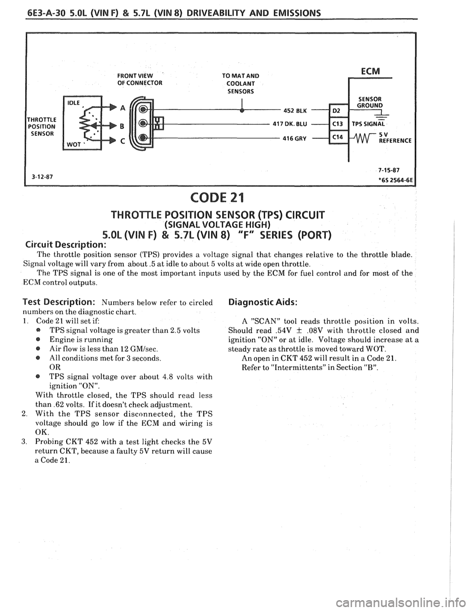
6E3-A-30 5.OL (VIN F) & 5.7L (VIN 8) DRIVEABILITY AND EMISSIONS
FRONT VIEW TO MAT AND
OF CONNECTOR
COOLANT
452
ELK D2
416 GRY - C14
CODE 21
THROmLE POSITION SENSOR (TPS) CIRCUIT
(SIGNAL VOLTAGE HIGH)
5.OL (VIN I") & 5.7L (VIN 8) 'T" SERIES (PORT)
Circuit Description:
The throttle position sensor (TPS) provides a voltage signal that changes relative to the throttle blade.
Signal voltage will vary from about
.5 at idle to about 5 volts at wide open throttle.
The TPS signal is one of the most important inputs used by the ECM for fuel control and for most of the
ECM control outputs.
Test Description: Numbers below refer to circled
numbers on the diagnostic chart.
1. Code 21 will set if:
@ TPS signal voltage is greater than 2.5 volts
@ Engine is running
@ Air flow is less than 12 GMIsec.
e All conditions met for 3 seconds.
OR
@ TPS signal voltage over about 4.8 volts with
ignition "ON".
With throttle closed, the TPS should read less
than .62 volts. If it doesn't check adjustment.
2. With the TPS sensor disconnected, the TPS
voltage should go low if the ECM and wiring is
OK.
Diagnostic Aids:
A "SCAN" tool reads throttle position in volts.
Should read
.54V f .08V with throttle closed and
ignition "ON" or at idle. Voltage should increase at a
steady rate as throttle is moved toward WOT.
An open in CKT 452 will result in
a Code 21.
Refer to "Intermittents" in Section
"B".
3. Probing CKT 452 with a test light checks the 5V
return CKT, because
a faulty 5V return will cause
a Code 21.
Page 837 of 1825
6E3-A-34 5.OL (VIN F) & 5.7L (VIN 8) DRIVEABILITY AND EMISSIONS
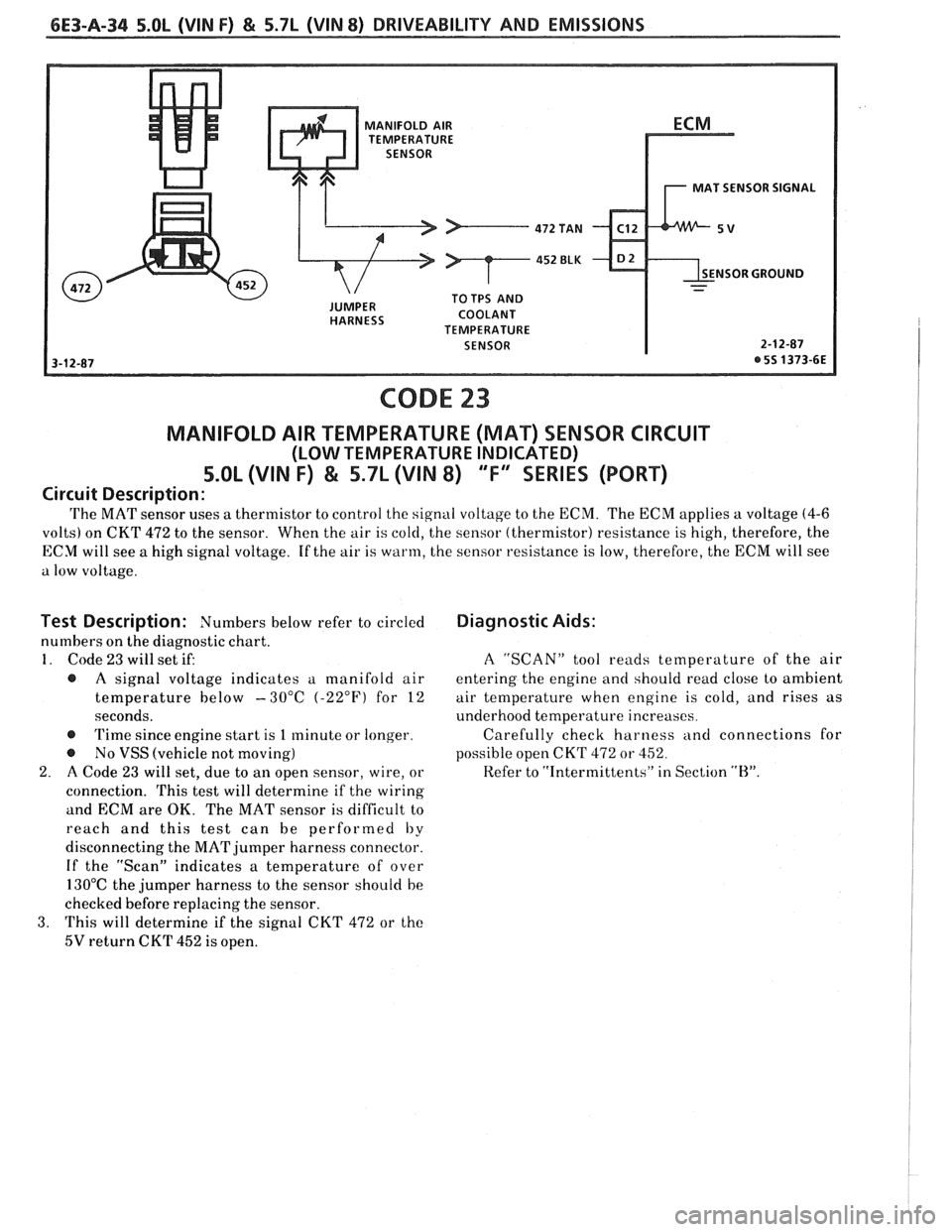
MANIFOLD AIR
TEMPERATURE
MAT SENSOR SIGNAL
NSOR GROUND
COOLANT
TEMPERATURE
SENSOR
CODE 23
MANIFOLD AIR TEMPERATURE (MAT) SENSOR CIRCUIT
(LOW TEMPERATURE INDICATED)
5.OL (VIN F) & 5.7L (VIN 8) "F" SERIES (PORT)
Circuit Description:
'I'he MAT sensor uses a thermistor to control the signal voltage to the ECM. The ECM applies a voltage (4-6
volts) on CKT 472 to the sensor. When the air is cold, the sensor (thermistor) resistance is high, therefore, the
ECY will see a high signal voltage. If the air is warm, the sensor resistance is low, therefore, the ECM will see
a low voltage.
Test Description: Numbers below refer to circled
numbers on the diagnostic chart.
1. Code 23 will set if:
@ A signal voltage indicates u manifold air
temperature below -30°C (-22°F) for
12
seconds.
@ Time since engine start is 1 minute or longer.
@ No VSS (vehicle not moving)
2. A Code 23 will set, due to an open sensor, wire, or
connection. This test will determine if the wiring
and ECM are OK. The MAT sensor is difficult to
reach and this test can be performed
by
disconnecting the MAT jumper harness connector.
If the "Scan" indicates a temperature of over
130°C the jumper harness to the sensor should be
checked before replacing the sensor.
3. This will determine if the signal CKT 472 or the
5V return CKT 452 is open.
Diagnostic Aids:
A "SCAN" tool reads temperature of the air
entering the engine and should read close to ambient
air temperature when engine is cold, and rises as
underhood temperature increases.
Carefully check harness
ancl connections for
possible open CKT
472 or 452.
Refer to "Intermittents" in Section
"H".