1988 PONTIAC FIERO light
[x] Cancel search: lightPage 1615 of 1825
8C.4 INSTRUMENT PANEL, GAGES & CONSOLE
ON-CAR SERVlCE
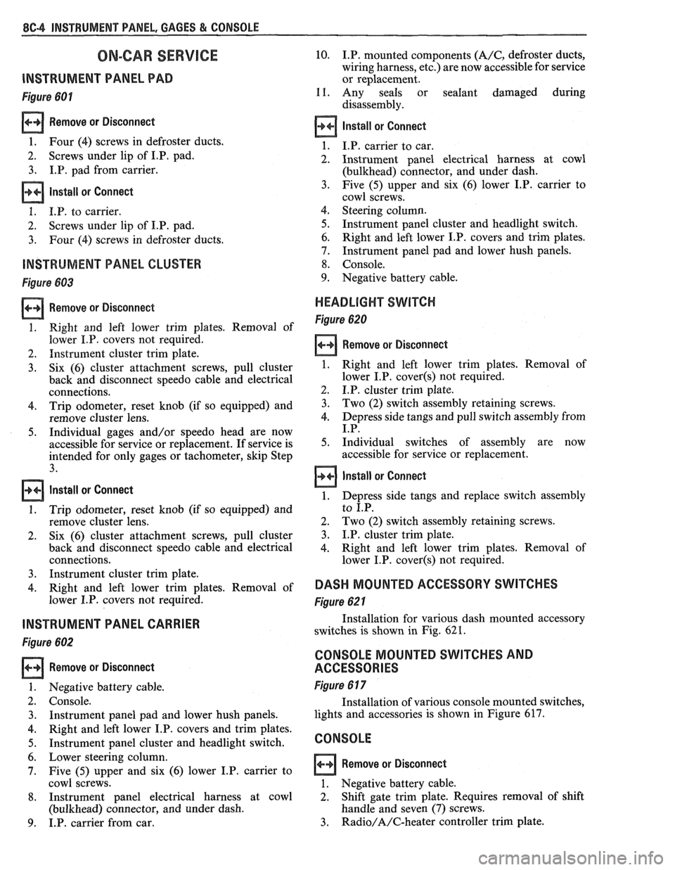
lNSTRUMEMT PANEL PAD
Figure 601
Remove or Disconnect
1. Four (4) screws in defroster ducts.
2. Screws
under lip of
I.P, pad.
3. I.P. pad from carrier.
lnstall or Connect
1. I.P. to carrier.
2. Screws
under lip of I.P. pad.
3. Four (4) screws in defroster ducts.
INSTRUMENT PANEL CLUSTER
Figure 683
Remove or Disconnect
1. Right and left lower trim plates. Removal of
lower I.P. covers not required.
2. Instrument cluster trim plate.
3. Six (6) cluster attachment screws, pull cluster
back and disconnect speedo cable and electrical
connections.
4. Trip odometer, reset knob (if so equipped) and
remove cluster lens.
5. Individual gages and/or speedo head are now
accessible for service or replacement. If service is
intended for only gages or tachometer, skip Step
3.
Install or Connect
1. Trip odometer, reset knob (if so equipped) and
remove cluster lens.
2. Six
(6) cluster attachment screws, pull cluster
back and disconnect speedo cable and electrical
connections.
3. Instrument cluster trim plate.
4. Right and left lower trim plates. Removal of
lower I.P. covers not required.
INSTRUMENT PANEL CARRIER
Figure 602
Remove or Disconnect
Negative battery cable.
Console. Instrument panel pad and lower hush panels.
Right and left lower I.P. covers and trim plates.
Instrument panel cluster and headlight switch.
Lower steering column.
Five (5) upper and six (6) lower I.P. carrier to
cowl screws.
Instrument panel electrical harness at cowl
(bulkhead) connector, and under dash.
I.P. carrier from car.
10. I.P. mounted components (A/C, defroster ducts,
wiring harness, etc.) are now accessible for service
or replacement.
11. Any seals or sealant damaged during
disassembly.
Install or Connect
I.P. carrier to car.
Instrument panel electrical harness at cowl
(bulkhead) connector, and under dash.
Five (5) upper and six (6) lower I.P. carrier to
cowl screws.
Steering column.
Instrument panel cluster and headlight switch.
Right and left lower I.P. covers and trim plates.
Instrument panel pad and lower hush panels.
Console.
Negative battery cable.
HEADLIGHT SWITCH
Figure 620
Remove or Disconnect
1. Right and left lower trim plates. Removal of
lower I.P.
cover(s) not required.
2. I.P. cluster trim plate.
3. Two (2) switch assembly retaining screws.
4. Depress side tangs and pull switch assembly from
I.P.
5. Individual switches of assembly are now
accessible for service or replacement.
Install or Connect
1. Depress side tangs and replace switch assembly
to I.P.
2. Two
(2) switch assembly retaining screws.
3. I.P. cluster trim plate.
4. Right and
left lower trim plates. Removal of
lower I.P.
cover(s) not required.
DASH MOUNTED ACCESSORY SWITCHES
Figure 62 1
Installation for various dash mounted accessory
switches is shown in Fig.
62 1.
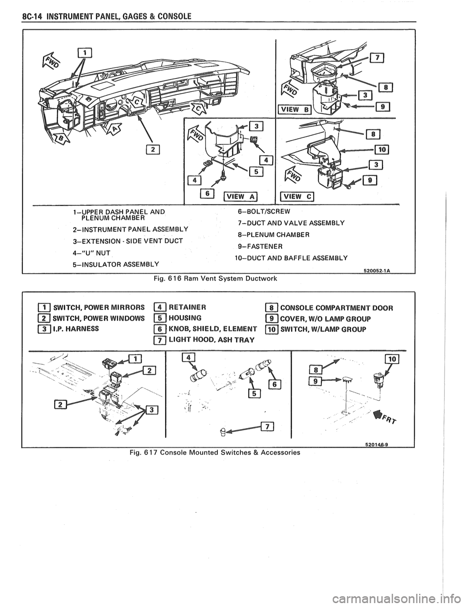
CONSOLE MOUNTED SWITCHES AND
ACCESSORIES
Figure 6 17
Installation of various console mounted switches,
lights and accessories is shown in Figure 617.
CONSOLE
Remove or Disconnect
1. Negative battery cable.
2. Shift gate trim plate. Requires removal
of shift
handle and seven (7) screws.
3. Radio/A/C-heater controller trim plate.
Page 1616 of 1825
INSTRUMENT PANEL, GAGES & CONSOLE 8C-5
4. A/C-heater controller (see Section 1B).
5. Radio (see Section 9A).
6. Electrical connectors (cigar lighter, ash tray light,
etc.) and pull harness forward out of console.
7. Six (6) console hold-down and two (2) console to
I.P. screws and remove console.
Install or Connect
1. Six (6) console hold-down and two (2) console to
I.P. screws and replace console.
2. Electrical connectors (cigar lighter, ash tray light,
etc.) and pull harness forward out of console.
3. Radio (see Section 9A).
4. A/C-heater controller (see Section 1B).
5. Radio/A/C-heater controller trim plate.
6. Shift gate trim plate.
7. Negative battery cable.
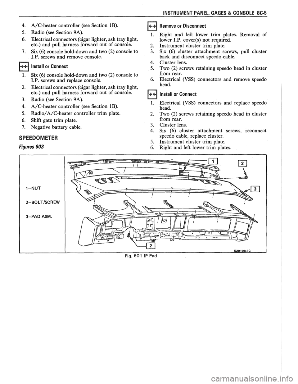
SPEEDOMETER
Figures 603
Remove or Disconnect
Right and left lower trim plates. Removal of
lower
I.P. cover(s) not required.
Instrument cluster trim plate.
Six (6) cluster attachment screws, pull cluster
back and disconnect speedo cable.
Cluster lens.
Two (2) screws retaining speedo head in cluster
from rear.
Electrical (VSS) connectors and remove speedo
head.
Install or Connect
Electrical (VSS) connectors and replace speedo
head.
Two (2) screws retaining speedo head in cluster
from rear.
Cluster lens.
Six (6) cluster attachment screws, reconnect
speedo cable, replace cluster.
Instrument cluster trim plate.
Right and left lower trim plates.
Page 1625 of 1825
8C14 INSTRUMENT PANEL, GAGES & CONSOLE
1-UPPER DASH PANEL AND 6-BOLTISCREW
PLENUM CHAMBER
7-DUCT AND VALVE ASSEMBLY
2-INSTRUMENT PANEL ASSEMBLY
8-PLENUM CHAMBER
3-EXTENSION
- SIDE VENT DUCT
4-"U" NUT
10-DUCT AND BAFFLE ASSEMBLY
Fig.
6 16 Ram Vent System Ductwork
SWITCH, POWER MIRRORS RETAINER a CONSOLE COMPARTMENT DOOR
SWITCH, POWER WINDOWS HOUSING
COVER, W/O LAMP GROUP
I.P. HARNESS
KNOB, SHIELD, ELEMENT SWITCH, \MILAMP GROUP
LIGHT HOOD, ASH TRAY
Fig. 6 17 Console Mounted Switches & Accessories
Page 1631 of 1825
8E -4 WINDSHIELD WIPER SYSTEMS - F CARLINE
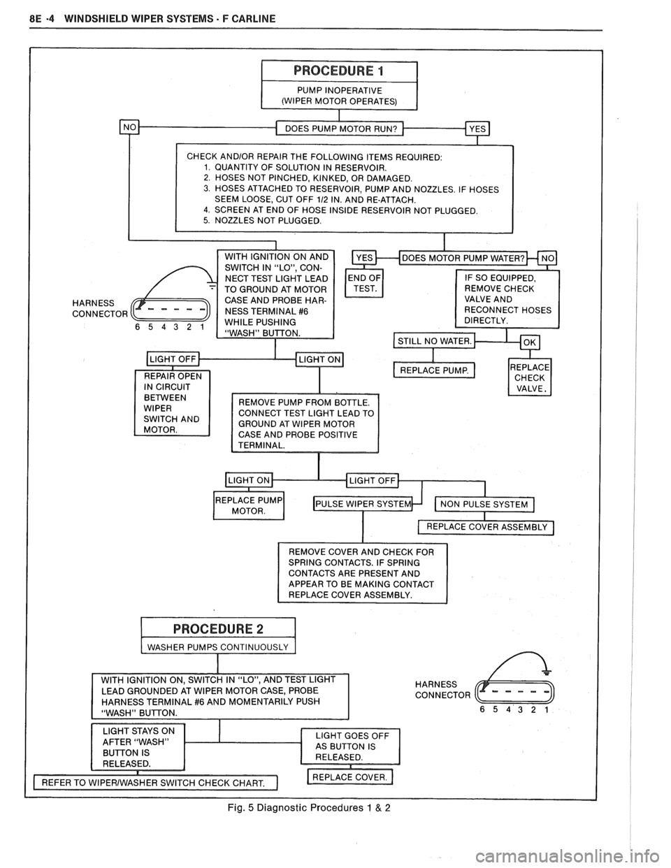
SEEM LOOSE, CUT OFF 112 IN. AND RE-ATTACH. 4. SCREEN AT END OF HOSE INSIDE RESERVOIR NOT PLUGGED.
HARNESS
CONNECTOR
CONNECT TEST LIGHT LEAD TO
GROUND AT WIPER MOTOR
CASE AND PROBE POSITIVE
I VALVE. I
t
REMOVE COVER AND CHECK FOR
SPRING CONTACTS. IF SPRING
CONTACTS ARE PRESENT AND
APPEAR TO BE MAKING CONTACT
REPLACE COVER ASSEMBLY.
I WASHER PUMPS CONTINUOUSLY I
HARNESS
CONNECTOR
Fig. 5 Diagnostic Procedures 1 & 2
Page 1636 of 1825
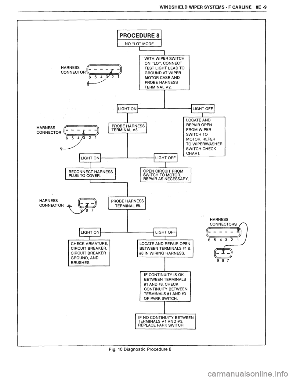
WINDSHIELD WIPER SYSTEMS - F CARLINE 8E -9
I PROCEDURE 8 I
NO "LO.' MODE I
WITH WIPER SWITCH
ON "LO", CONNECT
TEST LIGHT LEAD TO
GROUND AT WIPER
MOTOR CASE AND
PROBE HARNESS
TERMINAL
#2.
I PROBE C
I LOCATE AND
REPAIR OPEN
FROM WIPER
SWITCH TO
MOTOR. REFER
TO
WlPERlWASHER
SWITCH CHECK CHART.
RECONNECT HARNESS
PLUG TO COVER.
I
HARNESS
CONNECTOR OPEN CIRCUIT FROM
SWITCH TO MOTOR.
REPAIR AS NECESSARY.
2
PROBE HARNES
CHECK ARMATURE,
CIRCUIT BREAKER,
CIRCUIT BREAKER
GROUND, AND BRUSHES.
TERMINALS
#1 AND #3
I
IF NO CONTINUITY BETWEEN
TERMINALS #1 AND #3, REPLACE PARK SWITCH. I
HARNESS
I I Fig. 10 Diagnostic Procedure 8
Page 1640 of 1825
WINDSHIELD WIPER SYSTEMS - F CARLINE 8E -13
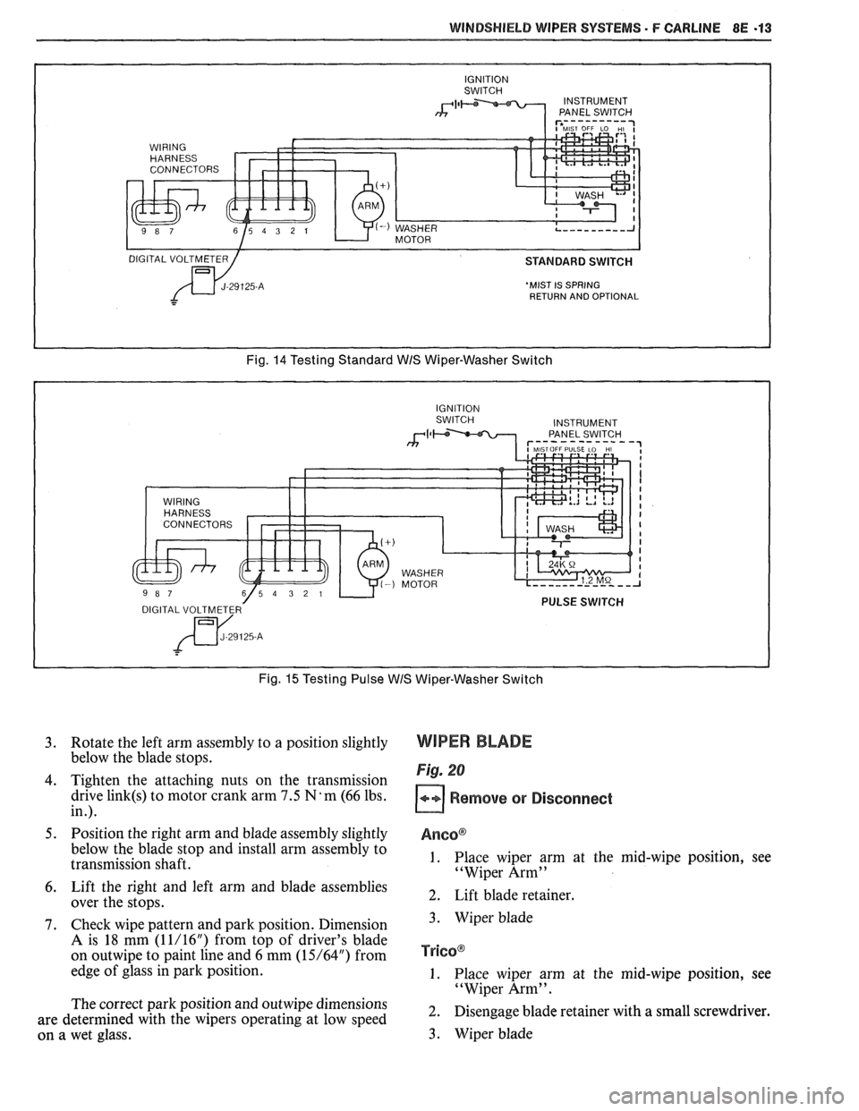
'MIST IS SPRING
RETURN AND OPTIONAL
Fig. 14 Testing Standard WIS Wiper-Washer Switch
Fig.
15 Testing Pulse WIS Wiper-Washer Switch
3. Rotate the left arm assembly to a position slightly
below the blade stops.
4. Tighten the attaching nuts on the transmission
drive
link(s) to motor crank arm 7.5 N'm (66 lbs.
in.).
5. Position the right arm and blade assembly slightly
below the blade stop and install arm assembly to
transmission shaft.
6. Lift the right and left arm and blade assemblies
over the stops.
7. Check wipe pattern and park position. Dimension
A is 18 mm (1 1/16") from top of driver's blade
on
outwipe to paint line and 6 mm (15/64") from
edge of glass in park position.
The correct park position and
outwipe dimensions
are determined with the wipers operating at low speed
on a wet glass.
WIPER BLADE
Fig. 20
Remove or Disconnect
Anso@
1. Place wiper arm at the mid-wipe position, see
"Wiper Arm"
2. Lift blade retainer.
3. Wiper blade
TY~GO@
1. Place wiper arm at the mid-wipe position, see
"Wiper Arm".
2. Disengage blade retainer with a small screwdriver.
3. Wiper blade
Page 1650 of 1825
RADIO SYSTEMS AND ANTENNAS 9A-1
SECTION 9A
0 SYSTEMS AND ANTENNAS
CONTENTS
............................................. General Description .................................... 9A-1 Radio Operation 9A-4
Radio
............................................................ 9A-1 ETR AM/FM Stereo (UM-7) ....................... 9A-4
Antennas
........................................................ 9A- 1 ETR Stereo Cassette (UM-6) ......................... 9A-5
Fixed Antenna
.......................................... 9A- 1 ETR Stereo/Cassette/Eaualizer
Diagnosis ........................................................
Radio ....................... .. ................................
Static and Noise .................................... .....
........................................ Popping Noise
Preliminary Diagnostics
.............................
Antenna ................................. .. ................
Tape Player .................. .... .......................
Service Procedures ....................................
Radio and Speakers ........................... .............
Radio Noise Suppression Equipment ............
Stereo Cassette Tape Player ..........................
Tape & Tape Player Care ........................
(UX-1) ..................................................... 9A-6
Advanced ETR
Stereo/Cassette/Equalizer Touch
Control
.................................... ... .............. 9A-7
On-Car Service .............................................. 9A-9
Radio Receiver
............................................ 9A-9
Radio Steering Wheel Controls
..................... 9A-9
Audio Amplifier
........................................... 9A-9
Radio Suppression
..................................... 9A-9
Front Speaker
................................................. 9A-9
............... Rear Speaker; Sub Woofer Speaker
9A-9
Antenna
..................... .. ............................. 9A- 10
GENERAL DESCRIPUION
RADIO ANTENNAS
For radios and radio use see the "Radio Fixed Antenna
Operation" section. ETR means 'Electronically Tuned The
fixed antenna on the right front fender
Receiver'. cannot be adjusted up or down. It may provide
improved reception in rural areas.
- The fixed antenna is designed to withstand most
car washes without damage. If the antenna becomes
slightly bent, you can straighten it by hand. The
antenna can be replaced if severely bent (by vandalism,
etc.). Antennas must be kept clean for good
performance.
RADIO
Because radio problems are normally repaired at
authorized warranty repair stations, the tendency is to
remove the set when a problem is reported, without any
preliminary diagnosis. This results in a large number
of radios being "No Trouble Found" units when
received by the warranty repair stations. Often the
trouble can be corrected without radio removal. wire.
If equipped with
A/C, the blower motor has a
built-in capacitor. Extra electrical equipment added to
the static if not properly grounded or wiring was
improperly routed.
Weak
FM station reception will be affected by
nearby buildings, car speed and direction. These
"flutter" and "fading" conditions are characteristic of
weak FM signals.
ETR radios require clock and button reset if the
battery is disconnected.
Popping Noise
Static and Noise Operating devices such as turn signals, pushing in
cigarette lighter, operating stop lights, etc., may cause
Ground strap connections must be clean and
a popping noise on distant (weak) AM signals.
tight, spark plug cables must be TVRS type and in
good condition and resistance-type spark plugs used.
Preliminary Diagnostics
Capacitors are used in the generator, heating/air
conditioning system, and fuse panel to reduce noise
The inconvenience of driving without a radio
entering the radio through the feed wires. If the car has
while the set is being serviced can often be avoided if
a heater only, the capacitor is in the blower motor feed
the following quick checks are used to eliminate
Page 1652 of 1825
RADIO SYSTEMS AND ANTENNAS 9A-3
antenna. Check radio reception in an area away from
reception. If reception is OK, problem exists with
electrical interferences. These include tall buildings,
antenna and/or its lead-in cable. If reception is still
metal structures, power lines, fluorescent lighting, and
poor, refer to Section
8A.
power tools. Tune to high and low ends of the dial on
both AM and FM checking weak and strong station
reception. If reception is OK, problem exists with
antenna and/or its lead-in cable. If reception is still
poor, refer to Section
8A.
Checking Lead-In Cables
Figure 2
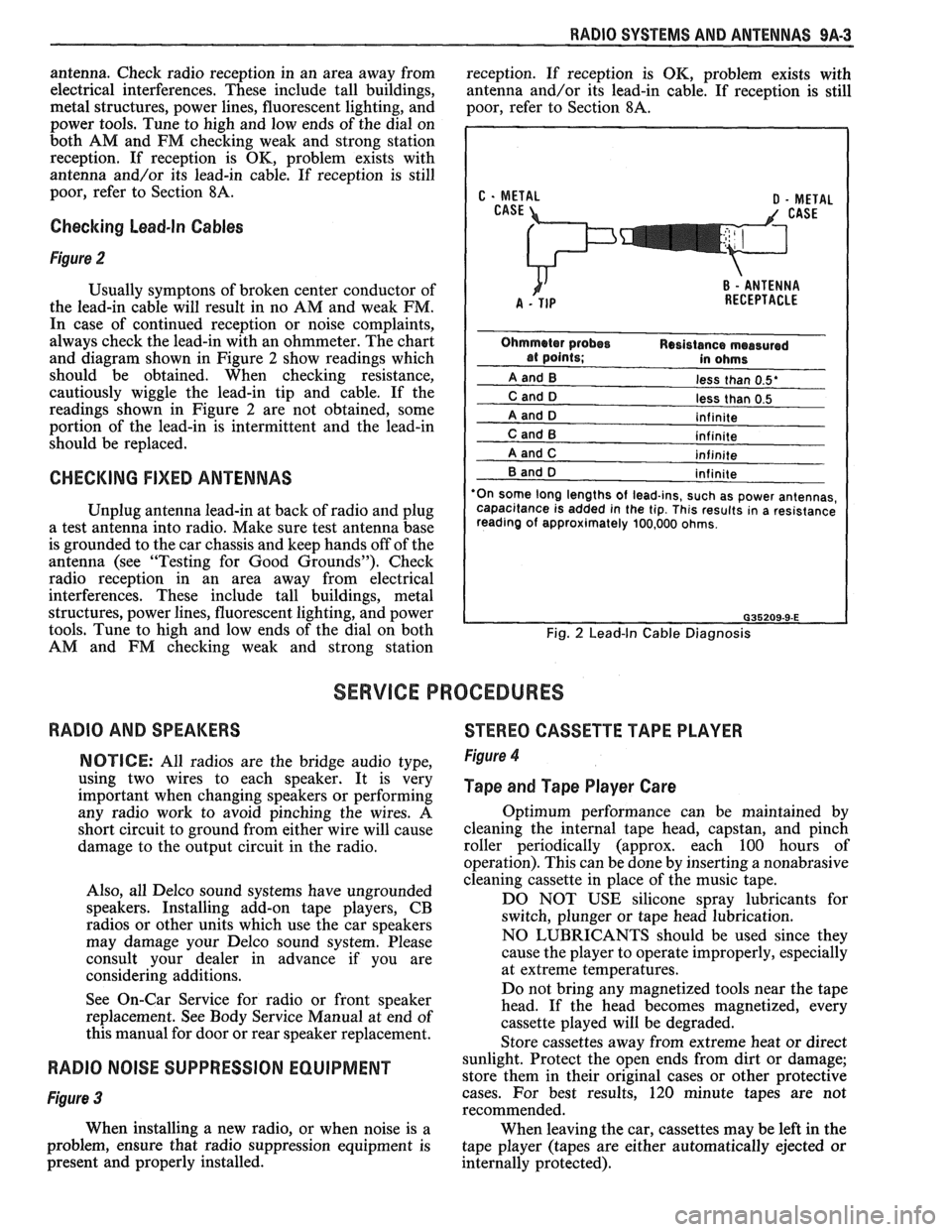
Usually symptons of broken center conductor of
the lead-in cable will result in no AM and weak FM.
In case of continued reception or noise complaints,
always check the lead-in with an ohmmeter. The chart
and diagram shown in Figure
2 show readings which
should be obtained. When checking resistance,
cautiously wiggle the lead-in tip and cable. If the
readings shown in Figure
2 are not obtained, some
portion of the lead-in is intermittent and the lead-in
should be replaced.
CHECKING FIXED ANTENNAS
Unplug antenna lead-in at back of radio and plug
a test antenna into radio. Make sure test antenna base
is grounded to the car chassis and keep hands off of the
antenna (see "Testing for Good Grounds"). Check
radio reception in an area away from electrical
interferences. These include tall buildings, metal
structures, power lines, fluorescent lighting, and power
tools. Tune to high and low ends of the dial on both
AM and FM checking weak and strong station
less than 0.5'
less than 0.5
'On some long lengths
of lead-ins, such as power antennas,
capacitance is added in the tip. This results in a resistance
reading of approximately 100,000 ohms.
Fig. 2 Lead-In Cable Diagnosis
SERVICE PROCEDURES
RADIO AND SPEAKERS
STEREO CASSETTE TAPE PLAYER
NOTICE: All radios are the bridge audio type,
using two wires to each speaker. It is very
important when changing speakers or performing
any radio work to avoid pinching the wires. A
short circuit to ground from either wire will cause
damage to the output circuit in the radio.
Also, all Delco sound systems have ungrounded
speakers. Installing add-on tape players, CB
radios or other units which use the car speakers
may damage your Delco sound system. Please
consult your dealer in advance if you are
considering additions.
See On-Car Service for radio or front speaker
replacement. See Body Service Manual at end of
this manual for door or rear speaker replacement. Figure 4
Tape and Tape Player Care
Optimum performance can be maintained by
cleaning the internal tape head, capstan, and pinch
roller periodically (approx. each 100 hours of
operation). This can be done by inserting a nonabrasive
cleaning cassette in place of the music tape.
DO NOT USE silicone spray lubricants for
switch, plunger or tape head lubrication.
NO LUBRICANTS should be used since they
cause the player to operate improperly, especially
at extreme temperatures.
Do not bring any magnetized tools near the tape
head. If the head becomes magnetized, every
cassette played will be degraded.
Store cassettes away from extreme heat or direct
RADIO NOISE SUPPRESSION EQUIPMENT sunlight. Protect the open ends from dirt or damage;
store them in their original cases or other protective
Figure 3 cases. For best results, 120 minute tapes are not
recommended.
When installing a new radio, or when noise is a
When leaving the car, cassettes may be left in the
problem, ensure that radio suppression equipment is
tape player (tapes are either automatically ejected or
present and properly installed.
internally protected).