1988 PONTIAC FIERO light
[x] Cancel search: lightPage 1674 of 1825
MISCELLANEOUS ACCESSORIES 96-4
SCELLANEOUS ACCESSOR
General Description ................................. 9G-1
Rally Gages .................................................. 9G- 1
Tachometer ................................................. 9G- 1
Trip Odometer
............................................. 9G- 1
Electric Rear Window Defogger ................. 9G-2
Power Remote Control Rearview
Mirror ........................................................ 9G-2
Diagnosis .................................................... 9G-2
Rally Gages ............................................... 9G-2
Tachometer .................................... .... .... 9G-2
Electric Rear Window Defogger ................. 9G-2
Power Remote Control Rearview
Mirror ........................................................ 96-2
Dash and Console Mounted
Accessory Switches
................................. 9G-4
General Description .................................. 9G-4
Electronic Glare Control Mirror ................. 9G-4
On-Car Service ............................................. 9G-4
Rally Gages, Tach ....................................... 96-4.
Rear Window Defogger ............................ 96-4.
Power Remote Control Mirror .................... 9G-4
GENERAL BESCRIP"T0N
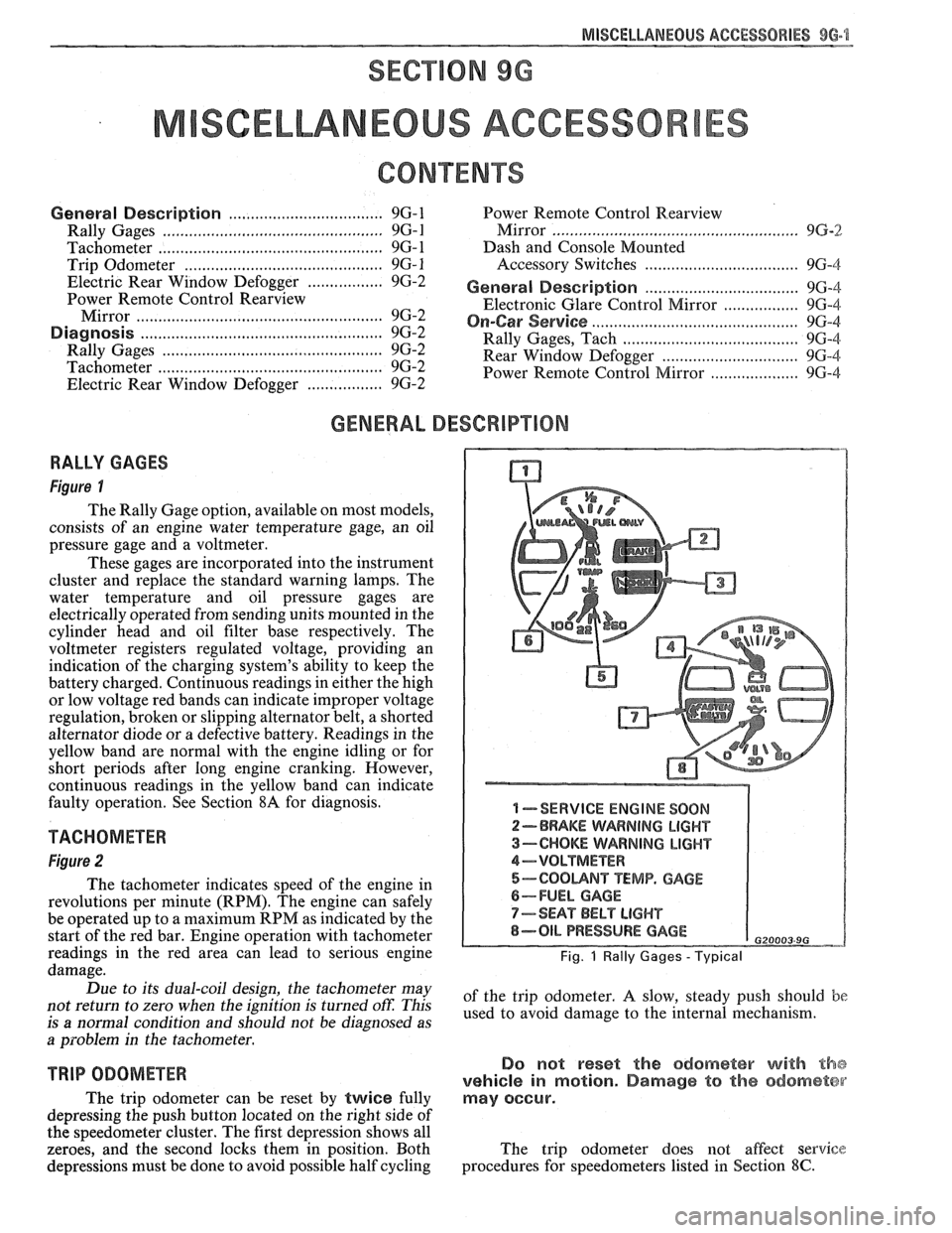
RALLY GAGES
Figure I
The Rally Gage option, available on most models,
consists of an engine water temperature gage, an oil
pressure gage and a voltmeter.
These gages are incorporated into the instrument
cluster and replace the standard warning lamps. The
water temperature and oil pressure gages are
electrically operated from sending units mounted in the
cylinder head and oil filter base respectively. The
voltmeter registers regulated voltage, providing an
indication of the charging system's ability to keep the
battery charged. Continuous readings in either the high
or low voltage red bands can indicate improper voltage
regulation, broken or slipping alternator belt,
a shorted
alternator diode
or a defective battery. Readings in the
yellow band are normal with the engine idling or for
short periods after long engine cranking. However,
continuous readings in the yellow band can indicate
faulty operation. See Section
8A for diagnosis.
TACHOMETER
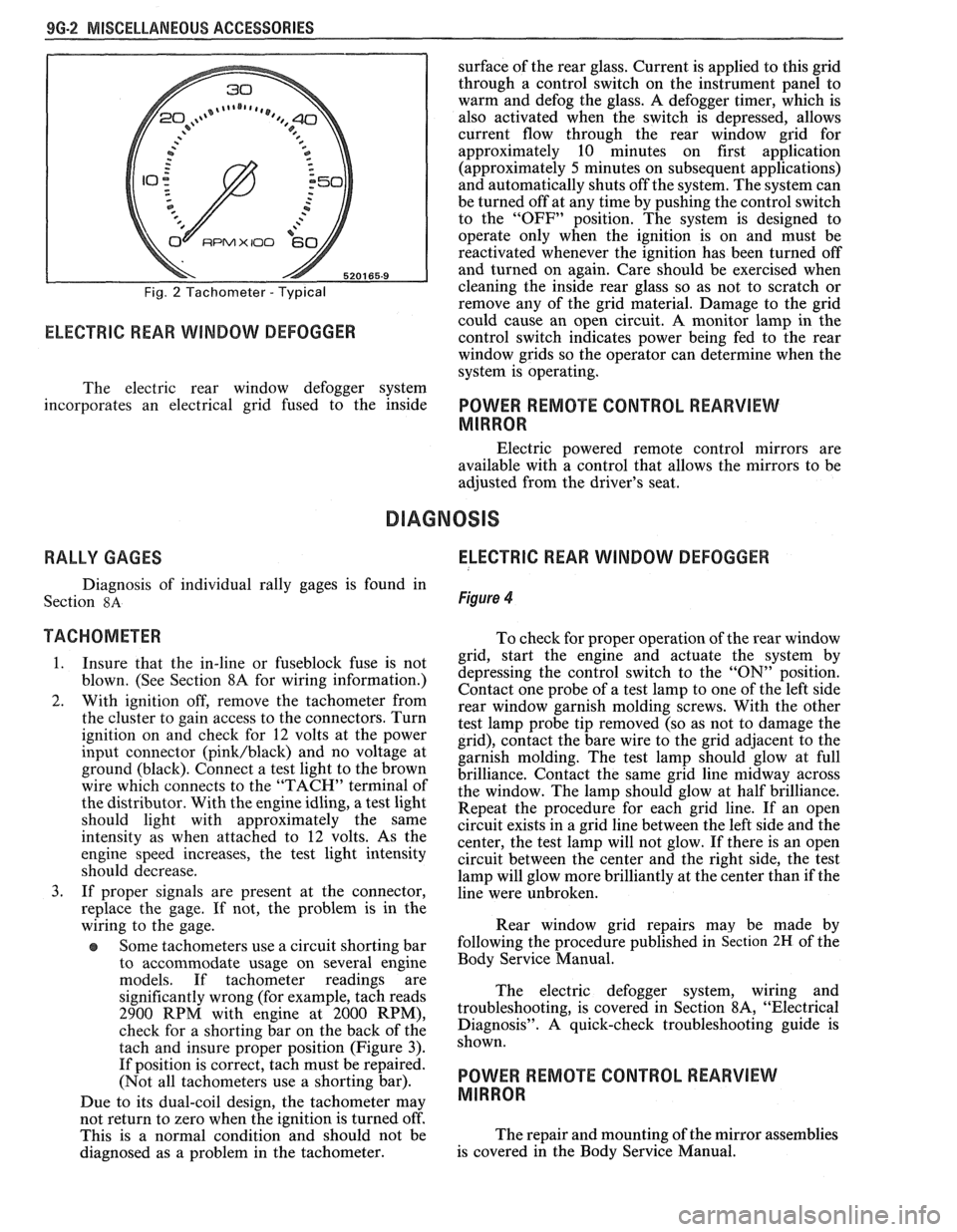
Figure 2
The tachometer indicates speed of the engine in
revolutions per minute (RPM). The engine can safely
be operated up to a maximum RPM as indicated by the
start of the red bar. Engine operation with tachometer
readings in the red area can lead to serious engine
damage.
Due to its dual-coil design, the tachometer may
not return to zero when the ignition
is turned oft: This
is
a normal condition and should not be diagnosed as
a problem in the tachometer.
TRIP ODOMETER
The trip odometer can be reset by twice fully
depressing the push button located on the right side of
the speedometer cluster. The first depression shows all
zeroes, and the second locks them in position. Both
depressions must be done to avoid possible half cycling
I -SERVICE ENGINE SOON
2-BRAKE WARNING LIGHT
3-CHOKE WARNING LIGHT
4-VOLTMETER
5-COOUNT TEMP. GAGE
6-FUEL GAGE
7-SEAT BELT LIGHT
8-OIL PRESSURE GAGE G20003 9G
Fig. 1 Rally Gages - Typical
of the trip odometer. A slow, steady push should be
used to avoid damage to the internal mechanism.
Do not reset the odometer with the
vehicle in motion. Damage to the odometer
may occur.
The trip odometer does not affect service
procedures for speedometers listed in Section
8C.
Page 1675 of 1825
9G-2 MISCELLANEOUS ACCESSORIES
Fig. 2 Tachometer - Typical
RPMX I00 €31-
ELECTRIC REAR WINDOW DEFOGGER
surface of the rear glass. Current is applied to this grid
through a control switch on the instrument panel to
warm and defog the glass. A defogger timer, which is
also activated when the switch is depressed, allows
current flow through the rear window grid
for
approximately 10 minutes on first application
(approximately
5 minutes on subsequent applications)
and automatically shuts off the system. The system can
be turned off at any time by pushing the control switch
to the "OFF" position. The system is designed to
operate only when the ignition is on and must be
reactivated whenever the ignition has been turned off
and turned on again. Care should be exercised when
cleaning the inside rear glass so as not to scratch or
remove any of the grid material. Damage to the grid
could cause an open circuit. A monitor lamp in-the
control switch indicates power being fed to the rear
window grids so the operator can determine when the
system is operating.
The electric rear window defogger system
incorporates an electrical grid fused to the inside
POWER REMOTE CONTROL REARVIEW
MIRROR
Electric powered remote control mirrors are
available with a control that allows the mirrors to be
adjusted from the driver's seat.
RALLY GAGES ELECTRIC REAR WINDOW DEFOGGER
Diagnosis of individual rally gages is found in
Section
8A Figure 4
TACHOMETER To check for moper o~eration of the rear window
1. Insure that the in-line or fuseblock fuse is not
blown. (See Section 8A for wiring information.)
2. With ignition off, remove the tachometer from
the cluster to gain access to the connectors. Turn
ignition on and check for
12 volts at the power
input connector
(pink/black) and no voltage at
ground (black). Connect a test light to the brown
wire which connects to the "TACH" terminal of
the distributor. With the engine idling, a test light
should light with approximately the same
intensity as when attached to
12 volts. As the
engine speed increases, the test light intensity
should decrease.
3. If proper signals are present at the connector,
replace the gage. If not, the problem is in the
wiring to the gage.
Some tachometers use a circuit shorting bar
to accommodate usage on several engine
models. If tachometer readings are
significantly wrong (for example, tach reads
2900 RPM with engine at 2000 RPM),
check for a shorting bar on the back of the
tach and insure proper position (Figure
3).
If position is correct, tach must be repaired.
(Not all tachometers use a shorting bar).
Due to its dual-coil design, the tachometer
may
- grid, start the engine a& actuate the system by
depressing the control switch to the
"ON" position.
Contact one probe of a test lamp to one of the left side
rear window garnish molding screws. With the other
test lamp probe tip removed (so as not to damage the
grid), contact the bare wire to the grid adjacent to the
garnish molding. The test lamp should glow at full
brilliance. Contact the same grid line midway across
the window. The lamp should glow at half brilliance.
Repeat the procedure for each grid line. If an open
circuit exists in a grid line between the left side and the
center, the test lamp will not glow. If there is an open
circuit between the center and the right side, the test
lamp will glow more brilliantly at the center than if the
line were unbroken.
Rear window grid repairs may be made by
following the procedure published in
Section 2H of the
Body Service Manual.
The electric defogger system, wiring and
troubleshooting, is covered in Section
8A, "Electrical
Diagnosis". A quick-check troubleshooting guide is
shown.
POWER REMOTE CONTROL REARVIEW
MIRROR
not return to zero when tvhe ignition is turned off'.
This is a normal condition and should not be The
repair and mounting of the mirror assemblies
diagnosed as a problem in the tachometer. is
covered in the Body Service Manual.
Page 1677 of 1825
96.4 MISCELLANEOUS ACCESSORIES
DASH AND CONSOLE MOUNTED ACCESSORY
SWITCHES
Installation for various dash and console
mounted accessory switches is shown in Section
8C.
GENERAL DESCRIPIIOM
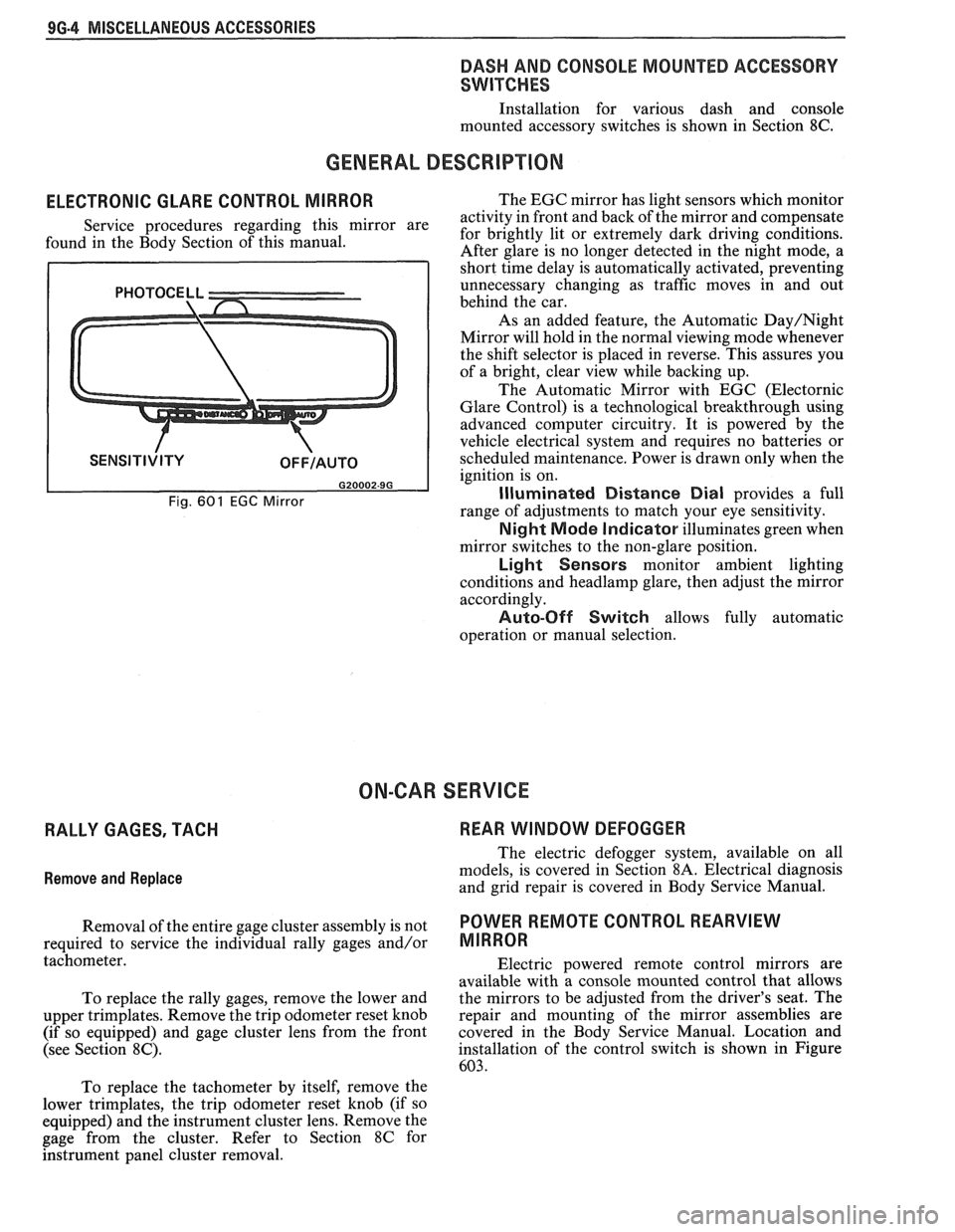
ELECTRONIC GLARE CONTROL MIRROR
Service procedures regarding this mirror are
found in the Body Section of this manual.
Fig. 601 EGC Mirror
The EGC mirror has light sensors which monitor
activity in front and back of the mirror and compensate
for brightly lit or extremely dark driving conditions.
After glare is no longer detected in the night mode, a
short time delay is automatically activated, preventing
unnecessary changing as traffic moves in and out
behind the car.
As an added feature, the Automatic
Day/Night
Mirror will hold in the normal viewing mode whenever
the shift selector is placed in reverse. This assures you
of a bright, clear view while backing up.
The Automatic Mirror with EGC (Electornic
Glare Control) is a technological breakthrough using
advanced computer circuitry. It is powered by the
vehicle electrical system and requires no batteries or
scheduled maintenance. Power is drawn only when the
ignition is on.
Illuminated Distance Dial provides a full
range of adjustments to match your eye sensitivity.
Night Mode Indicator illuminates green when
mirror switches to the non-glare position.
Light Sensors monitor ambient lighting
conditions and
headlamp glare, then adjust the mirror
accordingly.
Auto-Off Switch allows fully automatic
operation or manual selection.
ON-CAR SERVICE
RALLY GAGES, TACH REAR WINDOW DEFOGGER
Remove
and Replace
The electric defogger system, available on all
models, is covered in Section
8A. Electrical diagnosis
and grid repair is covered in Body Service Manual.
Removal of the entire gage cluster assembly is not
POWER RmOTE CONTROL REARVIEW
required to service the individual rally gages and/or MIRROR
tachometer.
Electric powered remote control mirrors are
available with a console mounted control that allows
To replace the rally gages, remove the lower and the
mirrors to be adjusted from the driver's seat. The
upper trimplates. Remove the trip odometer reset knob repair
and mounting of the mirror assemblies are
(if so equipped) and gage cluster lens from the front covered in
the Body Service Manual. Location and
(see Section
8C). installation of the control switch is shown in Figure
603.
To replace the tachometer by itself, remove the
lower trimplates, the trip odometer reset knob (if so
equipped) and the instrument cluster lens. Remove the
gage from the cluster. Refer to Section
8C for
hstrument panel cluster removal.
Page 1683 of 1825
1 H-2 GENERAL INFORMATION - F STYLE
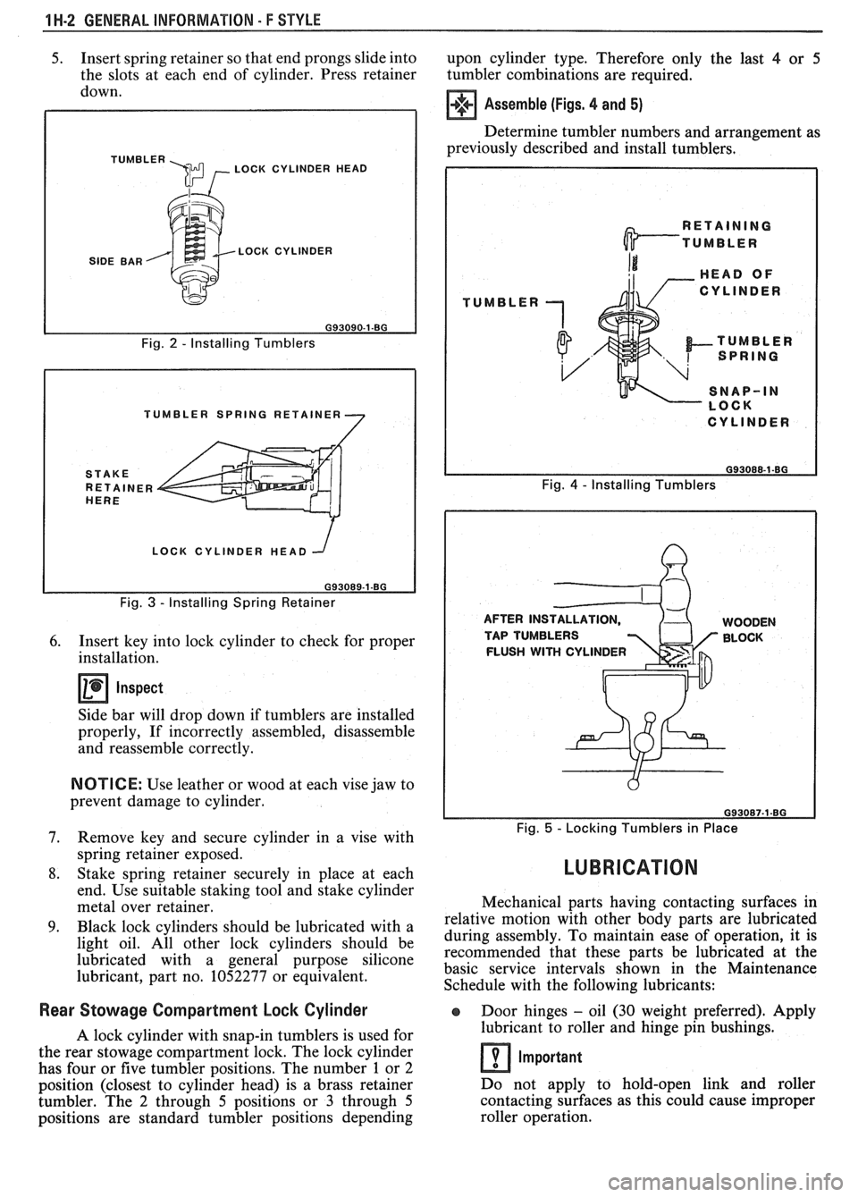
5. Insert spring retainer so that end prongs slide into
upon cylinder type. Therefore only the last 4 or 5
the slots at each end of cylinder. Press retainer
tumbler combinations are required.
down.
TUMBLER \m , LOCK CYLINDER HEAD
SIDE BAR LOCK CYLINDER
Fig.
2 - Installing Tumblers
TUMBLER SPRING RETAINER
LOCK CYLINDER HEAD
Fig.
3 - Installing Spring Retainer
6. Insert key into lock cylinder to check for proper
installation.
Inspect
Side bar will drop down if tumblers are installed
properly, If incorrectly assembled, disassemble
and reassemble correctly.
NOTICE: Use leather or wood at each vise jaw to
prevent damage to cylinder.
7. Remove key and secure cylinder in a vise with
spring retainer exposed.
8. Stake spring retainer securely in place at each
end. Use suitable staking tool and stake cylinder
metal over retainer.
9. Black lock cylinders should be lubricated with a
light oil. All other lock cylinders should be
lubricated with a general purpose silicone
lubricant, part no. 1052277 or equivalent.
Assemble (Figs. 4 and 5)
Determine tumbler numbers and arrangement as
previously described and install tumblers,
TUMBLER
I CYLINDER I
Fig. 4 - Installing Tumblers
AFTER INS WOODEN
TAP TUMBLERS BLOCK
FLUSH
WITH CYLINDER
Fig. 5 - Locking Tumblers in Place
LUBRICATION
Mechanical parts having contacting surfaces in
relative motion with other body parts are lubricated
during assembly. To maintain ease of operation, it is
recommended that these parts be lubricated at the
basic service intervals shown in the Maintenance
Schedule with the following lubricants:
Rear Stowage Compartment Lock Cylinder Door hinges - oil (30 weight preferred). Apply
A lock cylinder with snap-in tumblers is used for lubricant
to roller and hinge pin bushings.
the rear stowage compartment lock. The lock cylinder
Important has four or five tumbler positions. The number 1 or 2
position (closest to cylinder head) is a brass retainer Do
not apply to hold-open link and roller
tumbler. The
2 through 5 positions or 3 through 5 contacting
surfaces as this could cause improper
positions are standard tumbler positions depending roller operation.
Page 1684 of 1825
GENERAL INFORMAVlOM - F STYLE "1-3
Compartment lid hinges - part no. 1052196,
Lubriplate Auto Lube A; part no.
1052349,
Lubriplate Spray Lube A, part no. 8915,
3M
Lithium Spray Lube or equivalent.
Black lock cylinders
- light oil.
e All other lock cylinders - a general purpose
silicone lubricant, part no. 1052277 or equivalent.
e Seat mechanism and door hardware are covered
in the specific body area sections in this manual.
All weatherstrips should be periodically
lubricated with a silicone paste lubricant, part no.
1052363, or equivalent. A thin film of lubricant
should be applied using a clean cloth.
ADHESIVE BODY SlBE MOLDING
The body side moldings are attached to the body
panels with adhesive tape. To insure a good molding
replacement (new or old moldings), the panel surface
should be warm (21°C to 32°C or 70°F to
90°F), clean
and free of any wax or oily film. Two methods are listed
to attach loose molding ends and completely removed
m~ldings.
Molding End Loose
1. Wash affected area with soap and water and wipe
dry. Wipe panel and adhesive side of molding
with a clean rag using oil-free naphtha or alcohol.
If molding has pulled loose from adhesive
backing (tape remains on body panel), do not
remove tape from body. Clean back of molding
and tape on body with oil-free naphtha or alcohol
and proceed with step 3.
2. If needed, apply a length of masking tape as a
molding guide.
A straightedge may also be used
in most cases.
3. Apply adhesive to back of molding and press in
place. If Loctite
414 adhesive (part no. 1052283)
or equivalent is used, apply constant pressure to
molding for 30 seconds or until a firm bond has
been made.
Molding Completely Removed
1.
Wash affected panel area with soap and water
and wipe dry. Remove all traces of adhesive from
body panel and back of molding using oil-free
naphtha or alcohol.
2. Mark proper position of molding with a length of
masking tape. Use adjacent moldings as a guide,
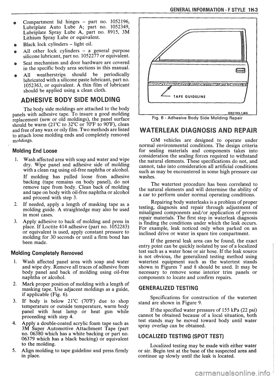
if applicable (Fig. 6).
3. If body is below 21°C (70°F) due to shop
temperature or outside temperature, warm body
panel with heat lamp or heat gun while
proceeding with step
4.
4. Apply a double-coated acrylic foam tape such as
3M Super Automotive Attachment Tape (part
no. 06380 which has a white backing or part no.
06379 which has a black backing) or equivalent
to the molding.
5. Align molding to tape guideline and press firmly
in place.
WATERLEAK DIAGNOSIS AND REPAIR
GM vehicles are designed to operate under
normal environmental conditions. The design criteria
for sealing materials and components takes into
consideration the sealing forces required to withstand
the natural elements. These specifications do not, and
cannot, take into consideration all artificial conditions
such as may be encountered in some high pressure car
washes.
The watertest procedure has been correlated to
the natural elements and will determine the ability of
a car to perform under normal operating conditions.
Repairing body waterleaks is a problem of proper
testing, diagnosis and repair through adjustment of
misaligned components and/or application of proven
repair materials. The first step in waterleak diagnosis
is finding the conditions under which the leak occurs.
For example, leak noticed only when parked on an
inclined drive or water in spare tire compartment.
If the general leak area can be found, the exact
entry point can be quickly isolated by use of a localized
test such as a water hose or air hose. If the leak source
is not obvious, the generalized testing method using
watertest equipment such as the watertest stands
shown in Figures
7 and 8 should be used. It may be
necessary to remove some interior trim panels or
components to locate and confirm repairs.
GENERALIZED TESTING
Specifications for construction of the watertest
stand are shown in Figure 9.
If the specified water pressure of 155
kPa (22 psi)
cannot be obtained because of a local situation, both
test stands may be moved toward body until water
spray overlap can be obtained.
LOCALIZED TEST lNG (SPOT TEST)
Localized testing may be made with either water
or air. Begin test at the base of the suspected area and
continue up slowly until the leak is located.
Page 1688 of 1825
GENERAL INFORMATION - F STYLE IN-7
DEADENER APPLICATION TO
INSIDE OF DOOR OUTER PANEL
I I
Fig. 17-Typical Application of Deadener Material
as anticorrosion barriers. Sealers are applied to such
areas as door and rear compartment lid hem flanges,
wheelhouse, quarter outer, floor, cowl, roof and
various other panel-to-panel attaching points. The
originally sealed joints are obvious and any damage to
these sealed locations should be corrected by resealing.
Attaching points of new replacement panels should be
resealed. Replacement lids and doors will also require
sealing in the hem flange areas.
Flanged joints, overlap joints and seams should
be sealed using a quality sealer of medium-bodied
consistency. Sealer used must retain its flexible
characteristics after curing and be paintable.
Open joints which require bridging of sealer to
close a gap should be sealed using a heavy-bodied
caulking material. Follow label directions for material
selected.
Color application may be required to restore
repaired areas such as hood, fenders, doors, quarters,
lid, roof, engine compartment, underbody and inner
panels to original appearance. When this is necessary,
conventional refinishing preparation, undercoat
build-up and color application techniques should be
followed.
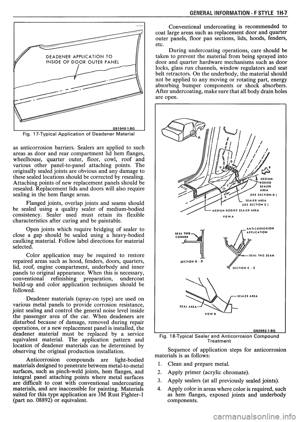
Deadener materials (spray-on type) are used on
various metal panels to provide corrosion resistance,
joint sealing and control the general noise level inside
the passenger area of the car. When deadeners are
disturbed because of damage, removed during repair
operations, or a new replacement panel is installed, the
deadener material must be replaced by a service
equivalent material. The application pattern and
location of deadener materials can be determined by
observing the original production installation.
Anticorrosion compounds are light-bodied
materials designed to penetrate between metal-to-metal
surfaces, such as pinch-weld joints, hem flanges, and
integral panel attaching points where metal surfaces
are difficult to coat with conventional undercoating
materials, and are inaccessible for painting. Materials
suited for this type application are
3M Rust Fighter-1
(part no. 08892) or equivalent. Conventional
undercoating is recommended to
coat large areas such as replacement door and quarter
outer panels, floor pan sections, lids, hoods, fenders,
etc.
During undercoating operations, care should be
taken to prevent the material from being sprayed into
door and quarter hardware mechanisms such as door
locks, glass run channels, window regulators and seat
belt retractors. On the underbody, the material should
not be applied to any moving or rotating part, energy
absorbing bumper components or shock absorbers.
After undercoating, make sure that all body drain holes
are open.
SEAL THIS SEAM
SECTION
D - 0
ECTlON C . C
SEALER AREA
Fig. 18-Typical Sealer and Anticorrosion Compound
Treatment
Sequence of application steps for anticorrosion
materials is as follows:
1. Clean and prepare metal.
2. Apply primer (acrylic chromate).
3. Apply sealers (at all previously sealed joints).
4. Apply color in areas where color is required, such
as hem flanges, exposed joints and underbody
components.
Page 1691 of 1825
1 W-10 GENERAL INFORMATION - F STYLE
Fig. 25-Tapering Substrate Surrounding Damage
Fig. 26-Tape Support for Repair Material
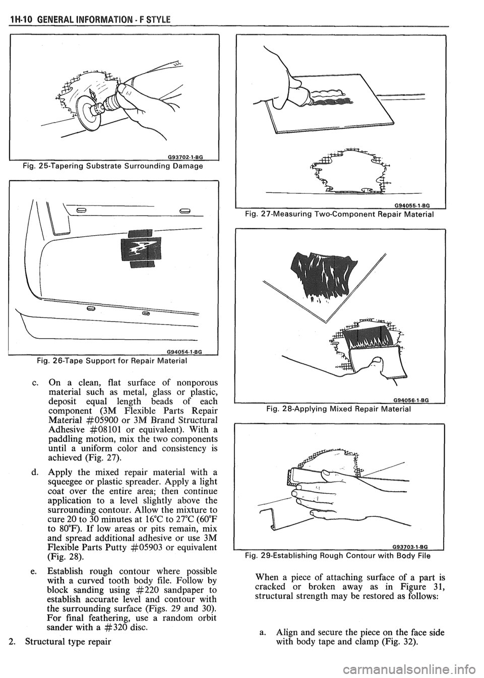
c. On a clean, flat surface of nonporous
material such as metal, glass or plastic,
deposit equal length beads of each
component (3M Flexible Parts Repair
Material
#05900 or 3M Brand Structural
Adhesive
#08101 or equivalent). With a
paddling motion, mix the two components
until a uniform color and consistency is
achieved (Fig. 27).
d. Apply the mixed repair material with a
squeegee or plastic spreader. Apply a light
coat over the entire area; then continue
application to a level slightly above the
surrounding contour. Allow the mixture to
cure 20 to 30 minutes at 16°C to 27°C (60°F
to 80°F). If low areas or pits remain, mix
and spread additional adhesive or use 3M
Flexible Parts Putty
#05903 or equivalent
(Fig. 28).
e. Establish rough contour where possible
with a curved tooth body file. Follow by
block sanding using
#220 sandpaper to
establish accurate level and contour with
the surrounding surface (Figs. 29 and 30).
For final feathering, use a random orbit
sander with a
#320 disc.
Fig. 27-Measuring Two-Component Repair Material
Fig. 29-Establishing Rough Contour with
Body File
When a piece of attaching surface of a part is
cracked or broken away as in Figure 31,
structural strength may be restored as follows:
a. Align and secure the piece on the face side
with body tape and clamp (Fig.
32). 2. Structural type repair
Page 1694 of 1825
GENERAL INFORMATION 5 F STYLE 1H-13
4. Prime entire area with 3M Polyolefin Adhesion
Promoter Part
kt05907 or equivalent before
filling with 3M Flexible Parts Repair Material
kt05900 or equivalent.
5. Shape repair material with curved body tooth file.
Then block sand with
#220 grit disc and final
featheredge with
#320 grit disc.
6. If low areas or pits remain, first reapply 3M
Polyolefin Adhesion Promoter or equivalent,
then mix and spread additional repair material.
Painting Flexible Parts - E/P or TPO
When painting flexible plastic exterior parts
identified as E/P or TPO, a polypropylene primer
must be used. Follow manufacturer's label
instructions.
METAL REPLACEMENWARTS
FINISHING
Metal service replacement parts (or assemblies)
are painted with a high-bake factory primer. For
proper adhesion of color coats in service, the following
refinish steps are necessary.
1. Clean part with a wax and grease-removing
solvent such as Prep-sol, Pre-Kleano,
Sher-Will-Clean, Acryli-Clean or equivalent.
2. Scuff-sand panel lightly with wet or dry no. 400
sandpaper and water. Avoid cut-throughs.
Reclean part. Apply sealer to entire part.
3. If factory primer coat was cut through, apply
metal conditioner to exposed bare metal. Follow
label directions.
4. Apply primer-surfacer to entire part; allow to dry
thoroughly before sanding. Follow label
directions for drying time.
5. Sand primer-surfacer using wet or dry no. 400
sandpaper and water. Do not sand sealer.
6. Reclean part.
7. Apply color coats to parts.
8. Follow label directions for drying time before
compounding.
9. Compound part by hand or with power
equipment.
10. Nonsealing polish may
be applied after rub-out if
desired. Waxes, however, should
not be applied
until the paint finish has aged at least two
months.
Prior to replacing exterior body parts or
assemblies, check condition of paint on all covered or
hidden interior surfaces.
If rust scale is found in these
areas, proceed as follows:
1. Remove rust with suitable wire brush, abrasive or
liquid rust removing agent. Follow label
directions.
2. If necessary, wash with detergent, rinse and dry.
3. Apply a heavy coating of anticorrosion
compound to all cleaned hidden surfaces before
installing exterior body parts. Also, apply
anticorrosion compound to all inner surfaces of
exterior body parts being installed.
INTERIOR PLASTBC TRIk7 PARTS
FINISHING
Paintable plastic interior trim components can be
divided into three general types:
Polypropylene Plastic
@ ABS Plastic
e Vinyl Plastic
It is important for a painter to be able to identify
each plastic in order to paint it satisfactorily. Painting
of complete soft seat cushion and
seatback trim cover
assemblies of vinyl construction is not approved by the
factory. Excluding the soft seat cushion and seat back
trim cover assemblies, the plastic used most widely on
the interior of bodies is polypropylene.
The purpose of the following tests is to determine
the identity of a given plastic so that proper paint
procedures and materials can be used.
Pest for Polypropylene and ABS Plastic
To determine if a service part to be painted is
polypropylene or
ABS plastic, perform the following
burn test:
1. From a hidden backside portion of the part,
remove a sliver of plastic with a sharp blade.
2. While holding the sliver of plastic with tweezers
or laying it on a clean noncombustible surface,
ignite the plastic.
3. Observe the burning plastic closely:
a. Polypropylene burns with no readily visible
smoke.
b. ABS plastic burns with a readily visible
black smoke residue which hangs
temporarily in the air.
Pest for Vinyl Plastic
To determine if a part to be painted is vinyl plastic
(polyvinyl chloride), a copper wire test should be
performed as follows:
1. Heat a copper wire in a suitable flame such as
provided by a propane or equivalent torch until
the wire glows (turns red).
2. Touch the heated wire to the backside or hidden
surface of the part being
testsd in a manner so as
to retain some of the plastic on
the wire.
3. Return the wire (and retained plastic) to the
flame and observe for a green, turquoise blue
flame. A flame in this color range indicates that
the plastic being tested is vinyl.
4. If black smoke residue, which hangs temporarily
in the air, is readily visible when wire (with
retained plastic residue) is returned to the flame,
the part is made of flexible (soft)
ABS plastic
material.
PAINTING POLYPROPYLENE PLASTIC PARTS
The system for painting polypropylene parts
involves the use of a special primer. Since
polypropylene plastic is hard, it can be
color coated
after prime with conventional interior acrylic lacquer.