1988 PONTIAC FIERO light
[x] Cancel search: lightPage 1756 of 1825
REAR END - F STYLE 7W-13
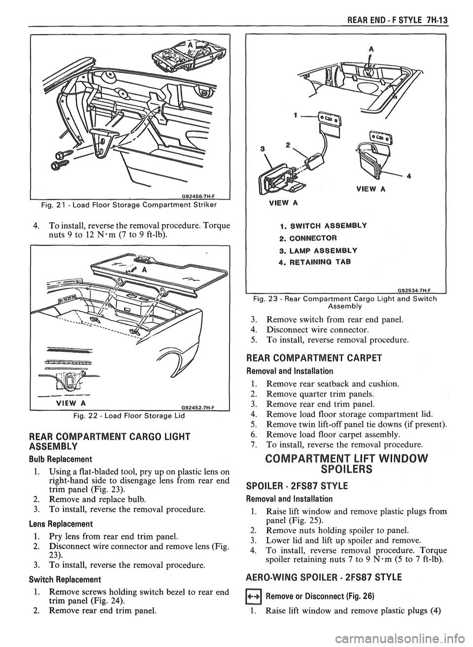
Fig. 2 1 - Load Floor Storage Compartment Striker
4. To
install, reverse the removal procedure. Torque
nuts
9 to 12 N-m (7 to 9 ft-lb).
Fig. 22 - Load Floor Storage Lid
REAR COMPARTMENT CARGO LIGHT
ASSEMBLY
Bulb Replacement
1. Using a flat-bladed tool, pry up on plastic lens on
right-hand side to disengage lens from rear end
trim panel (Fig. 23).
2. Remove and replace bulb.
3. To install, reverse the removal procedure.
Lens Replacement
1. Pry lens from rear end trim vanel.
2. Disconnect wire connector and remove lens (Fig.
23).
3. ~d install, reverse the removal procedure.
Switch Replacement
1. Remove screws holding switch bezel to rear end
trim panel (Fig. 24).
2. Remove rear end trim panel.
VlEW A
1. SWITCH ASSEMBLY
2. CONNECTOR
8. LAMP ASSEMBLY
4. RETAINING TAB
Fig. 23 - Rear Compartment Cargo Light and Switch
Assembly
3. Remove
switch from rear end panel.
4. Disconnect wire connector.
5. To
install, reverse removal procedure.
WEAR COMPARTMENT CARPET
Removal and Installation
1. Remove rear seatback and cushion.
2. Remove quarter trim panels.
3. Remove rear end trim panel.
4. Remove load floor storage compartment lid.
5. Remove twin lift-off panel tie downs (if present).
6. Remove load floor carpet assembly.
7. To install, reverse the removal procedure.
GOMPARTMEN"FLlFT WINDOW
SPOILERS
SPOILER - 2FS87 STYLE
Removal and lnstallation
1. Raise lift window and remove plastic plugs from
panel (Fig. 25).
2. Remove nuts holding spoiler to panel.
3. Lower lid
and lift up spoiler and remove.
4. To install, reverse removal procedure. Torque
spoiler retaining nuts
7 to 9 N.m (5 to 7 ft-lb).
AERO-WING SPOILER - 2FS87 STYLE
a Remove or Disconnect (Fig. 26)
1. Raise lift window and remove plastic plugs (4)
Page 1757 of 1825
7H-14 REAR END - F STYLE
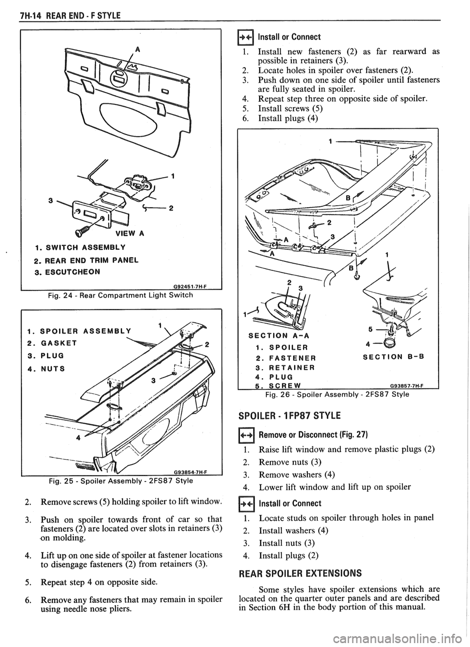
1. SWITCH ASSEMBLY
2. REAR END TRIM PANEL
3. ESCUTCHEON
Fig. 24 - Rear Compartment Light Switch
Fig.
25 - Spoiler Assembly - 2FS87 Style
2. Remove screws (5) holding spoiler to lift window.
3. Push on spoiler towards front of car so that
fasteners
(2) are located over slots in retainers (3)
.on molding.
4. Lift up on one side of spoiler at fastener locations
to disengage fasteners
(2) from retainers (3).
5. Repeat step 4 on opposite side.
6. Remove any fasteners that may remain in spoiler
using needle nose pliers.
Install or Connect
1. Install new fasteners (2) as far rearward as
possible in retainers
(3).
2.
Locate holes in spoiler over fasteners (2).
3. Push down on one side of spoiler until fasteners
are fully seated in spoiler.
4. Repeat step three on opposite side of spoiler.
5. Install screws (5)
6. Install plugs (4)
1. SPOILER 4-w
2. FASTENER SECTION B-8
Fig. 26 - Spoiler Assembly - 2FS87 Style
SPOILER - 1 FP87 STYLE
Remove or Disconnect (Fig. 27)
1. Raise lift window and remove plastic plugs (2)
2.
Remove nuts (3)
3. Remove washers (4)
4. Lower lift window and lift up on spoiler
Install or Connect
1. Locate studs on spoiler through holes in panel
2. Install washers (4)
3.
Install nuts (3)
4.
Install plugs (2)
REAR SPOILER EXTENSIONS
Some styles have spoiler extensions which are
located on the quarter outer panels and are described
in Section
6H in the body portion of this manual.
Page 1761 of 1825
8H-2 ROOF - F SWLE
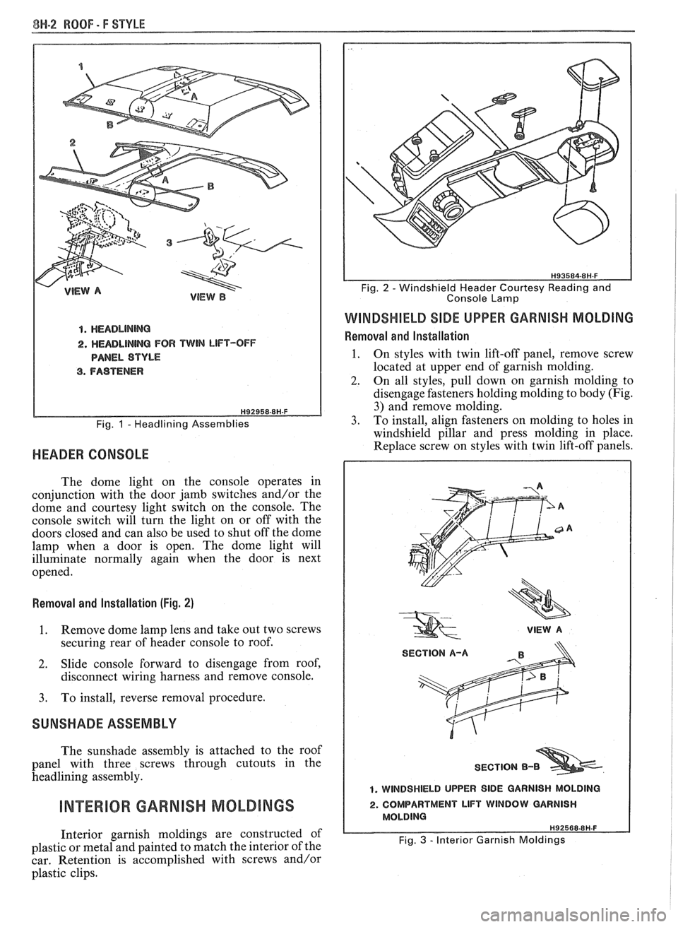
4. HEADLINMG
2. HEADLINING FOR TWIN LIFT-OFF
PANEL STYLE
3. FASTENER
Fig. 1 - Headlining Assemblies
HEADER CONSOLE
The dome light on the console operates in
conjunction with the door jamb switches and/or the
dome and courtesy light switch on the console. The
console switch will turn the light on or off with the
doors closed and can also be used to shut off the dome
lamp when a door is open. The dome light will
illuminate normally again when the door is next
opened.
Removal and Installation (Fig. 2)
1. Remove dome lamp lens and take out two screws
securing rear of header console to roof.
2. Slide console forward to disengage from roof,
disconnect wiring harness and remove console.
3. To install, reverse removal procedure.
SUNSHADE ASSEMBLY
The sunshade assembly is attached to the roof
panel with three screws through cutouts in the
headlining assembly.
INTERIOR GARNISH MOLDINGS
Interior garnish moldings are constructed of
plastic or metal and painted to match the interior of the
car. Retention is accomplished with screws and/or
plastic clips.
Console Lamp
WINDSHIELD SIDE UPPER GARNISH MOLDING
Removal and Installation
1. On styles with twin lift-off panel, remove screw
located at upper end of garnish molding.
2. On all styles, pull down on garnish molding to
disengage fasteners holding molding to body (Fig.
3) and remove molding.
3. To install, align fasteners on molding to holes in
windshield pillar and press molding in place.
Replace screw on styles with twin lift-off panels.
VIEW A
SECTION A-A
SECTION
B-B
1. WINDSHIELD UPPER SIDE GARNISH MOLDING
2. COMPARTMENT LIFT WINDOW GARNISH
MOLDING H92568-8H-F
Fig. 3 - Interior Garnish Moldings
Page 1763 of 1825
8N-4 WOOF - F STYLE
Removal and lnstallation
The twin lift-off glass panels can be removed and
stored in two storage bags located in the rear
compartment.
1. Remove
glass panel by moving inward on the
release handle.
2. Pivot entire glass upward slightly and pull
outward to disengage glass panel from under
center upper finishing molding.
3. Store glass panel(s) in storage bag(s).
4. To
install, place edge of glass panel on top of
weatherstrip lip, lift slightly and carefully insert
glass under center upper finishing molding.
Lower and latch in place.
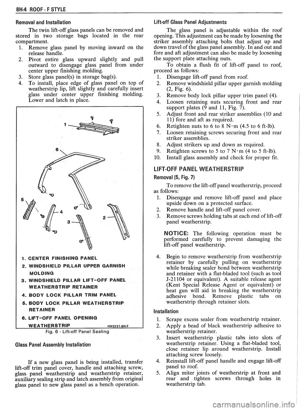
1. CENTER FINISHING PANEL
2. WINDSHIELD PILLAR UPPER GARNISH
MOLDING
3. WINDSHIELD PILLAR LIFT-OFF PANEL
WEATHERSTRIP RETAINER
4. BODY LOCK PILLAR TRIM PANEL
6. BODY LOCK PILLAR WEATHERSTRIP
RETAINER
6. LIFT-OFF PANEL OPENING
WEATHERSTRIP HS~Z~~-~H-F
Fig. 6 - Lift-off Panel Sealing
Glass Panel Assembly Installation
If a new glass panel is being installed, transfer
lift-off trim panel cover, handle and attaching screw,
glass panel weatherstrip and weatherstrip retainer,
auxiliary sealing strip and latch assembly from original
glass panel to new glass panel as a bench operation.
Lift-off Glass Panel Adjustments
The glass panel is adjustable within the roof
opening. This adjustment can be made by loosening the
striker assembly attaching bolts that adjust up and
down travel of the glass panel assembly. In and out and
fore and aft adjustment can also be made by loosening
the support plate attaching nuts.
To obtain a flush fit of lift-off panel to roof,
proceed as follows:
1. Disengage lift-off panel from roof.
2. Remove windshield pillar upper garnish molding
(2, Fig. 6).
3. Remove body lock pillar upper trim panel (4).
4. Loosen retaining nuts securing front and rear
support plates (9 and
11, Fig. 7).
5. Adjust front and rear striker assemblies (10 and
11) fore and aft as required.
6. Retighten nuts to 6 to 8 N.m (4.5 to 6 ft-lb).
7. Loosen retaining screws securing front and rear
striker assemblies.
8. Adjust strikers up and down as required.
9. Retighten screws to 5 to
7 N-m (4 to 5 ft-lb).
10. Install
glass assembly and check for proper fit.
LIFT-OFF PANEL WEATHEWSTRIP
Removal (5, Fig. 7)
To remove the lift-off panel weatherstrip, proceed
as follows:
1. Disengage and remove lift-off panel and place
upside down on a protected surface.
2. Remove handle and lift-off panel cover.
3. Remove screws holding tabs at each end of lift-off
panel weatherstrip.
NOTICE: The following operation must be
performed carefully to prevent damaging the
lift-off panel weatherstrip.
4. Begin
to remove weatherstrip from weatherstrip
retainer by carefully pulling on weatherstrip
while breaking sealer bond between weatherstrip
and retainer with a flat-bladed tool (such as tool
J-21104 or equivalent). A suitable release agent
(Kent Special Release Agent or equivalent) or
heat gun will aid in breaking the weatherstrip
adhesive bond. Remove plastic tabs on
weatherstrip through retainer slots.
Installation
1. Scrape
excess sealer from weatherstrip retainer.
2. Apply
a bead of black weatherstrip adhesive to
weatherstrip retainer.
3. Insert weatherstrip plastic tabs into slots of
weatherstrip retainer. Using a flat-bladed tool,
close retainer lip around weatherstrip. Install
attaching screw loosely.
4. Reinstall
lift-off panel handle and engage lift-off
panel to roof.
5. Align miter joints of weatherstrip at front and
rear and tighten screws through holes in
weatherstrip tab.
Page 1770 of 1825
ROOF - F STYLE 8H-11
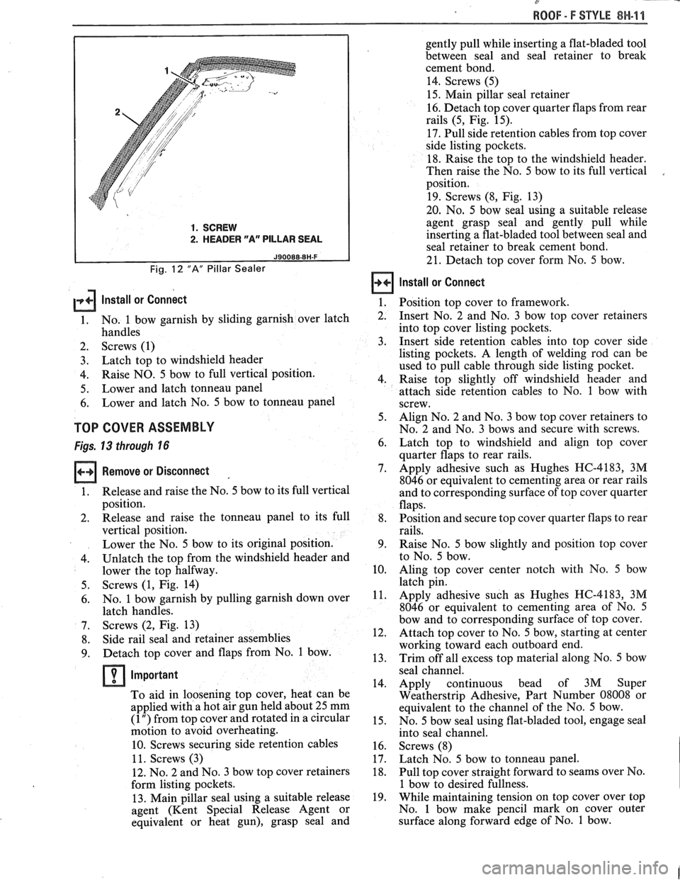
1. SCREW
2. HEADER "Ar' PILLAR SEAL
Fig. 12 "A" Pillar Sealer
gently pull while inserting a flat-bladed tool
between seal and seal retainer to break
cement bond.
14. Screws (5)
15. Main pillar seal retainer
16. Detach top cover quarter flaps from rear
rails (5, Fig. 15).
17. Pull side retention cables from top cover
side listing pockets.
18. Raise the top to the windshield header.
Then raise the No. 5 bow to its full vertical
position.
19. Screws (8, Fig. 13)
20. No. 5 bow seal using a suitable release
agent grasp seal and gently pull while
inserting a flat-bladed tool between seal and
seal retainer to break cement bond.
21. Detach top cover form No. 5 bow.
Install or Connect
lnstall or connect 1. Position top cover to framework.
1. No.
1 bow garnish by sliding garnish over latch
2. Insert No. 2 and No. 3 bow top cover retainers
handles into
top cover listing pockets.
2. Screws (1) 3. Insert side retention cables into top cover side
3. Latch
top to windshield header listing pockets.
A length of welding rod can be
used to pull cable through side listing pocket.
4. Raise
NO. 5 bow to full vertical position.
4. Raise top slightly off windshield header and
5. Lower
and latch tonneau panel
attach side retention cables to No. 1 bow with
6. Lower
and latch No. 5 bow to tonneau panel
screw.
TOP COVER ASSEMBLY
Figs. 13 through 16 6. 5.
Align
No. 2 and No. 3 bow top cover retainers to
No. 2 and No. 3 bows and secure with screws.
Remove or Disconnect 7.
1. Release
and raise the No. 5 bow to its full vertical
position.
2. Release and raise the tonneau panel to its full 8,
vertical position.
Lower the No. 5 bow to its original position. 9.
4. Unlatch the top
from the windshield header and
lower the top halfway.
10.
Screws (1, Fig. 14)
No. 1 bow garnish by pulling garnish down over
latch handles.
Screws (2, Fig. 13)
Side rail seal and retainer assemblies
Detach top cover and flaps from No. 1 bow.
Important
To aid in loosening top cover, heat can be
applied with a hot air gun held about 25 mm
(1 ") from top cover and rotated in a circular
motion to avoid overheating.
10. Screws securing side retention cables
1 1. Screws (3)
12. No. 2 and No. 3 bow top cover retainers
form listing pockets.
13. Main pillar seal using a suitable release
agent (Kent Special Release Agent or
equivalent or heat gun), grasp seal and Latch
top to windshield and align top cover
quarter flaps to rear rails.
Apply adhesive such as Hughes HC-4183, 3M
8046 or equivalent to cementing area or rear rails
and to corresponding surface of top cover quarter
flaps.
Position and secure top cover quarter flaps to rear
rails.
Raise No. 5 bow slightly and position top cover
to No. 5 bow.
Aling top cover center notch with No. 5 bow
--. latch pin.
Apply adhesive such as Hughes HC-4183, 3M
8046 or equivalent to cementing area of No. 5
bow and to corresponding surface of top cover.
Attach top cover to No. 5 bow, starting at center
working toward each outboard end.
Trim off all excess top material along No. 5 bow
- seal channel.
14. Apply continuous bead of 3M Super
Weatherstrip Adhesive, Part Number 08008 or
equivalent to the channel of the No. 5 bow.
15. No. 5 bow seal using flat-bladed tool, engage seal
into seal channel.
16. Screws (8)
17. Latch No. 5 bow to tonneau panel.
18. Pull top cover straight forward to seams over No.
1 bow to desired fullness.
19. While maintaining tension on top cover over top
No. 1 bow make pencil mark on cover outer
surface along forward edge of No. 1 bow.
Page 1790 of 1825
SEATS - F STYLE 9H-7
~
RECLINER CONTROL MECHANISM
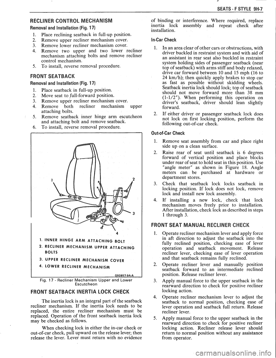
Removal and Installation (Fig. 17)
1. Place reclining seatback in full-up position.
2. Remove
upper recliner mechanism cover.
3. Remove lower recliner mechanism cover.
4. Remove two upper and two lower recliner
mechanism attaching bolts and remove recliner
control mechanism.
5. To install, reverse removal procedure.
FRONT SEATBACK
Removal and Installation (Fig. 17)
1. Place seatback in
full-up position.
2. Move seat to full-forward position.
3. Remove upper recliner mechanism cover.
4. Remove both recliner mechanism upper
attaching bolts.
5. Remove seatback inner hinge arm escutcheon
and attaching bolt and remove seatback.
6. To
install, reverse removal procedure.
1, INNER HINGE ARM ATTACHING BOLT
2. RECLINER MECHANISM UPPER ATTACHING
3. UPPER RECLINER MECHANISM COVER
4. LOWER RECLINER MECHANISM
G92857-9A-A
Fig. 17 - Recliner Mechanism Upper and Lower
Escutcheon
FRONT SEATBACK INERTIA LOCK CHECK
The inertia lock is an integral part of the seatback
recliner mechanism. If the inertia lock needs to be
replaced, the entire recliner mechanism must be
replaced. Operation of the front
seatback inertia lock
may be checked as follows.
When checking lock in either the in-car check or
out-of-car check, pull upward on the release lever; then
release the lever. Lever must return with no evidence of
binding or interference. Where required, replace
inertia lock assembly and repeat check after
installation.
In-Car Check
1. In an area clear of other cars or obstructions, with
driver buckled in restraint system and with aid of
an assistant in rear seat also buckled in restraint
system holding sides of passenger
seatback (near
top of seatback) with arms stiff and body relaxed,
drive car forward between
10 and 15 mph (16 to
24
km/h); then quickly apply brakes to stop car
as fast as possible without skidding wheels.
Seatback inertia lock should lock; top of seatback
should not move forward more than 38 mm
(1-1/2"). When performing this operation on
driver's seatback, driver should lean slightly
forward.
2. If either driver or passenger
seatback lock does
not lock on first locking position, perform the
following out-of-car check.
Out-of-Car Check
1.
Remove seat assembly from car and place right
side up on a clean surface.
2. Raise rear of seat until seatback is 6 degrees
forward of vertical position and place blocks
under rear of seat to hold seat in this position. Use
"angle meter" as shown in Figure
18. Angle
meters can be purchased at hardware or
department stores.
3. Check that seatbaclc lock locks seatback in
locking position. If lock does not
lock, remove
lock and install new lock assembly.
4. If installing a new lock, check that lock
mechanism moves freely prior to installation.
After installation, check lock as described in steps
1 through 3.
FRONT SEAT MANUAL RECLINER CHECK
1.
Operate recliner mechanism lever and apply force
in aft direction to adjust the
seatback into the
fully reclined position, checking ease of lever
operation and
seatback movement. Release
recliner lever, checking ease of lever operation
and that
seatback remains fully reclined.
2. Operate recliner lever and manually position
seatback forward to an intermediate reclined
position. Release recliner lever.
3. Apply manual force to the upper seatback in the
rearward direction to check for positive recliner
locking action.
4. Operate recliner mechanism lever to adjust the
seatback to normal position, checking ease of
lever operation and
seatback full return. Release
recliner lever.
5. Apply manual force to the upper seatback in the
rearward direction to check for positive recliner
locking action. Recliner release lever should
return to normal position without any assistance
from operator.
Page 1793 of 1825
8'
9H-10 SEATS - F STYLE
4. One adjuster will 1. Vertical drive cable 1. Check vertical drive
not operate vertically. disconnected or damaged. cables, replace if damaged.
2. Vertical gearnut 2. Replace vertical
inoperative. actuator assembly.
5. Both adjusters will 1. Inoperative horizontal 1. See chassis manual
not operate horizon- and/or vertical solenoid Section
8A.
tally and/or verti- in transmission.
cally. 2. Damaged, broken or 2. Replace damaged, broken
inoperable solenoid or inoperable solenoid part
plunger, shaft, dog, dog
with new part.
spring, gear or drive
gear.
6. Vertical chuck or
1. Excessive clearance at
1. Grind down top of verti-
looseness. vertical
gearnut tension cal gearnut shoulder nut
spring. 0.40 to 1.19 mm
(1/64" to
3.64") maximum.
Front Seat Adjustments
Seat Adjustment at Floor Pan Attachment
A small amount of fore and aft or side adjustment
is available at the seat adjuster-to-floor pan attaching
bolts which can be used toward alignment of the seat
assembly or alignment of the seat adjusters with each
other. This adjustment can be used to help correct the
following conditions:
1. Nard or slow operation due to adjusters not being
parallel with each other.
2. Passenger side of manually operated seat must be
moved forward or rearward slightly to engage in
locked position due to one adjuster being forward
or rearward of the other.
3. Seat assembly slightly too far to right or left.
Power Six-Way Seat Adjuster Horizontal Actuator
Adjustment
With seat adjuster assembly installed on seat or
seat installed in body, horizontal movement (chucking)
can be corrected by adjusting the horizontal actuator
and pinion gear in tight to the adjuster lower track rack
gear as follows:
Adjust -
1. Operate seat to full-up position and about 3/4
full-forward position.
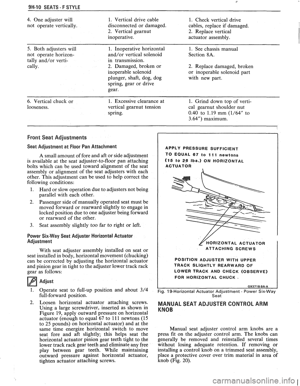
Loosen horizontal actuator attaching screws.
Using a large screwdriver, inserted as shown in
Figure
19, apply outward pressure on horizontal
actuator (enough to equal 67 to
11 1 newtons (15
to
25 pounds) on horizontal actuator) and at the
same time energize horizontal switch to move
seat fore and aft slightly; this helps seat the
horizontal actuator pinion gear teeth tight to the
lower track rack gear teeth and eliminate any free
play between gear teeth. While maintaining
outward pressure against horizontal actuator,
tighten actuator attaching screws.
APPLY PRESSURE SUFFICIENT
TO EQUAL
67 to 11 1 newtone
(15 to 26 Ib8.) ON HORIZONTAL
ACTUATOR
[HORIZONTAL ACTUATOR
ATTACHING SCREWS
POSITION ADJUSTER
WITH UPPER
TRACK SLIGHTLY REARWARD OF
LOWER TRACK AND CHECK (OBSERVE)
FOR HORIZONTAL CHUCK.
Fig. 19-Horizontal Actuator Adjustment - Power Six-Way
Seat
MANUAL SEAT ADJUSTER CONTROL ARM
KNOB
Manual seat adjuster control arm knobs are a
press fit on the adjuster control arm. The knobs can
generally be removed and reinstalled several times
without losing adequate retention. If removing or
installing a control knob on a trimmed seat assembly,
place a protective cover over trim material in area of
knob (Fig. 20).
Page 1812 of 1825
BODY INDEX . F STYLE 1
BODY INDEX
a
ABS and Polypropylene Plastic Test .............. 1 H- 13
Actuator. Power Door Lock
.......................... 5H-20
Adhesive-backed Moldings. Emblems. Name Plates
.................................................... 7FI-1
Adhesive Body Side Molding ............................ 1H-3
Adhesive Service
Kit . Stationary Glass ........... 2H-2
Adjuster
. Manual and Power Seats .......... 9H.12. 15
Alignment Checking
. Underbody .................... 3H-1
Anticorrosion Treatment
................................... 1H-4
Armrest
. Door ................................................. 5H-1
Assembling and Coding
Lock Cylinders ............ 1H-1
B
Body
Lock Pillar Trim Finishing Panel
................. 6H-1
Side Hinge Strap
......................................... 5H-10
I 'entilation ................................... .... ............... 4H-1
bonded
Rearview Mirror Support .................... 2H-5
Bucket Seat. High Performance
...................... 9H- 15
C
............................. Cable . Hood Latch Release 4H-1
Cargo Light
. Rear Compartment .................. 7H- 13
..................................................... Carpet 3H.2,7 H. 13
Center High Mounted Stop Lamp
.................. 7H-16
Child Seat
........................................................... 9H-2
Chip Resistant Plastisol Material
...................... 1H-8
...................................... Coding Lock Cylinders 1
H- 1
Colors for Interior Plastic Parts ...................... 1H-14
............................. Compartment Lift Window 7H-2
Garnish Molding
........................................ 8H-2
Glass
Replacement/Adjustment .................... 7H-5
Release Solenoid
.......................................... 7H-9
.......................................................... Spoiler 7H- 13
.................................................. Trim Panel 7H- 1 1
................................................ Weatherstrip 7H- 1 1
Cwnecting/Locking Rods, Doors .................. 5H- 16 I . itrol Arm Knob . Manual Seat .................. 9H-10
Convertible Top
................................................ 8H-7
Cover Assembly
. Luggage Shade ..................... 6H-4
................................................... Cutting Keys 1H- 1
D
............................ Deflector. Inner Panel Water 5H-6
Defogger
. Rear Window .................................. 2H-6
Diagnosis Chart
................................... Manual Seat Adjusters 9H-8
Power Six-Way Seat Adjuster
....................... 9H-9
Dome Lamps
...................................................... 8H-1
Boor Armrest and Pull Handle
.............................. 5H-1
Bell Crank
.................................................... 5H-20
Hardware Lubrication
................................. 5H- 19
Hinges
............................................................. 5H-7
Inner Panel Water Deflector
......................... 5H-6
Inside Handles and Cover Plate
.................... 5H-1
Inside Remote Handle
................................. 5H-16
Insulator Pads
............................................. 5H-6
Jamb Switch
................................................. 5H-19
Lock
.............................................................. 5H- 19
Lock Knob
..................................................... 5H-2
................................................. Lock Striker 5H- 17
............................................ Outside Handle 5H- 16
Outside Mirror
................................... 5H- 1.5 H. 15
Trim Assemblies
............................................ 5H-2
................................................... Weatherstrip 5H-4
................................................. Wedge Plate 5H-18
....................................... Window Assembly 5H- 10
...................................... Belt Sealing Strips 5H-6
........................................ Filler Assembly 5H- 13
.......................................... Front Up Stop 5H-14
................................ Rear Guide Channel 5H- 15
Regulator/Motor .................................... 5H-11
...................................... Door Side Hinge Strap 5H-8
Emblems.
Name Plates and Moldings .
Rear Compartment ........................................ 7H-I
. ....................................... Emblems Roof Panel 8H-3
. ............................. Exterior Lamps Rear End 7H-15
Exterior Moldings
Doors
............................................................ 5H-20
............................................... Rear Quarters 6H-6
.............................................................. Roof 8W-3
Finishing Panel. Quarter Lower Trim .............. 6H-1
Flexible Exterior Plastic Parts
.......................... 1H-9 .
.................................. E/P or TPO Repair 1H-12
Floor Carpet
................................................... 3H-2
Floor Pan Insulators
............................ .. ........ 3H-1
Folding Rear
Seatback ........................ ... ...... 9H- 19
Formed Headlining
.......................................... 8H-1
........................................................ Front End 4H-1
.......................................................... Front Seat 9H-5
............ Adjuster Assembly. Manual/Power 9H- 1 1
................................................... Adjustment 9H- 10
........................... Assembly. Manual/Power 9H- 1 1
................................................................ Back 9H-7
. ................................ Belt Warning System .... 9H-1
................... High Performance Bucket Seat 9H-
15
............................... Manual Control Knob 9H- 10
................................. Manual Recliner Check 9H-7
........................................ Power Seat Switch 9H- 15
............................................. Reclining Back 9H-6
............................... Seatback Head Restraint 9H-5
.................. Seatback Lock Striker/Bar Stop 9H-15
................................. Shoulder Belt Retractor 9H-2
................................. Six-way Seat Adjuster 9H-12
................................... Torque Specifications 9H-8
Fuel Tank Filler
Door/Pocket ........................ 6H-7
Gas Support
. Compartment Lift
........................................................... Window 7H-7
............................... General Body Construction 3H-1
.......................................... General Information 1H-1
Glass Installation
........................................... Extended Method 2H-4
................................................. Short Method 2H-3
...................................... Glass Scratch Removal 2H- 1