1988 PONTIAC FIERO light
[x] Cancel search: lightPage 1695 of 1825
1 H-14 GENERAL INFORMATION - F STYLE
NOTICE: Service part must be primed with a
coating of special polypropylene primer according
to factory recommendations. Failure to use the
required primer as directed will result in color coat
lifting and/or peeling problems. Use
Polypropylene Primer, part no. 1052364, or
equivalent.
1. Wash part with a solvent such as Acryli-Clean,
Pre-Kleano, Prep-Sol or equivalent. Follow label
directions.
2. Apply
a thin, wet coat of polypropylene primer
according to label directions. Wetness of primer
is determined by observing gloss reflection of
spray application in adequate lighting. Be sure
primer application includes all edges. Allow
primer to flash dry one minute minimum and ten
minutes maximum.
3. During the above flash time period (1 to 10
minutes), apply conventional interior acrylic
lacquer color as required and allow to dry before
installing part. Application of color during above
flash time range promotes best adhesion of color
coats.
PAINTING RIGID OR HARD ABS PLASTIC
PARTS
Rigid or hard ABS plastic requires no primer.
Conventional interior acrylic lacquers adhere
satisfactorily to hard ABS plastics.
1. Wash part with a solvent such as ~cr~li-clean,
Pre-Kleano, Prep-Sol or equivalent.
2. Apply conventional interior acrylic lacquer color
according to trim combination (see paint supplier
color chart for trim and color code). Apply only
enough color for proper hiding to avoid washout
of "grain" effect.
3. Allow to dry following label directions and then
install part.
PAINTING VINYL AND FLEXIBLE (SOFT) ABS
PLASTIC PARTS
The outer cover material of flexible instrument
panel cover assemblies is made mostly of ABS plastic
modified with PVC or vinyl. The same is true of many
padded door trim assemblies. The soft cushion padding
under
ABS covers is urethane foam plastic.
The most widely used flexible vinyls (polyvinyl
chloride) are coated fabrics as used in seat trim, some
door trim assemblies, headlinings and sunshades. Most
head restraints are covered with flexible vinyls.
Examples of hard vinyls are door and front
seatback
assist handles, coat hooks and exterior molding inserts. The
paint system for vinyl and flexible
ABS
plastic involves the use of interior vinyl color and a
clear vinyl top coat, No primer or primer-sealer is
required.
1. Wash part with a vinyl cleaning and preparation
solvent, such as Vinyl Prep, Vinyl Prep
Conditioner or equivalent. Wipe off cleaner while
still wet with clean, lint-free cloth.
2. As soon as the surface has been wiped dry, apply
interior vinyl color in wet coats. Allow flash time
between coats. Follow label directions. Use
proper vinyl color as shown by interior trim code
combination. Apply only enough color for proper
hiding to avoid washout of grain effect.
3. Before color flashes completely, apply one wet
double coat of vinyl clear top coat. Use top coat
with appropriate gloss level to match adjacent
similar components. The clear coat is necessary
to control the gloss requirement and to prevent
crocking (rubbing-off) of the color coat after
drying.
4. Allow to dry according to label directions before
installing part.
AVAILABILITY OF COLORS FOR PAINTING
INTERIOR PLASTIC PARTS
Interior colors are color keyed to trim code
combination numbers located on the body number
plate or service parts identification label.
Conventional interior acrylic lacquer colors are
designed for use only on hard trim parts, such as:
1. Steel parts (primer and/or sealer required on new
service parts)
2. Hard
ABS plastic (no primer necessary)
3. Hard polypropylene plastic (special primer
required)
Each major paint supplier provides an interior
color chart which identifies the stock number, color
name, gloss factor and trim code combination number
for each conventional interior color.
Vinyl interior colors are designed for soft trim
parts such as instrument panel cover assemblies, door
trim assemblies and head restraints. These colors
require a final top coat of clear vinyl. Instrument panel
covers require a nonglare final top coat. Other trim
parts require a degree of gloss to match similar
adjacent parts. Use interior vinyl colors and clear vinyl
finishes such as Ditzler Vinyl Spray Colors, American
Jetway UR-1 Vynicolor or equivalents.
SPECIAL BODY TOOLS
Figure 38 shows the special body tools that are
recommended as aids in servicing the various body
components. Equivalent tools may be substituted.
Page 1701 of 1825
2H-4 STATIONARY GLASS - F STYLE
7. Watertest car at once using soft spray. Use warm
or hot water if available. Do not direct hard
stream of water at fresh adhesive material. If any
leaks are found, paddle in extra adhesive at leak
point using a small disposable brush or
flat-bladed tool. Water applied on top of urethane
adhesive, either during watertest or as a separate
operation, will speed up the cure of the urethane.
8. Install windshield reveal molding.
9. Install
all other previously removed parts and
clean up.
10. On windshield installations, car must remain at
normal room temperature for six hours to
complete proper cure of adhesive.
Extended Method
It will be necessary to use extended installation
method if prior service installation was made with
butyl tape or if urethane material remaining in window
opening after window removal is damaged, or must be
removed to permit refinishing of window opening.
Spacers are used to maintain the dimensions of
the windshield stand off from the pinchweld flange.
The spacers are specific to certain styles and can be
found in the service parts manual. Spacers should be
reused or replaced before reinstallation of windshield
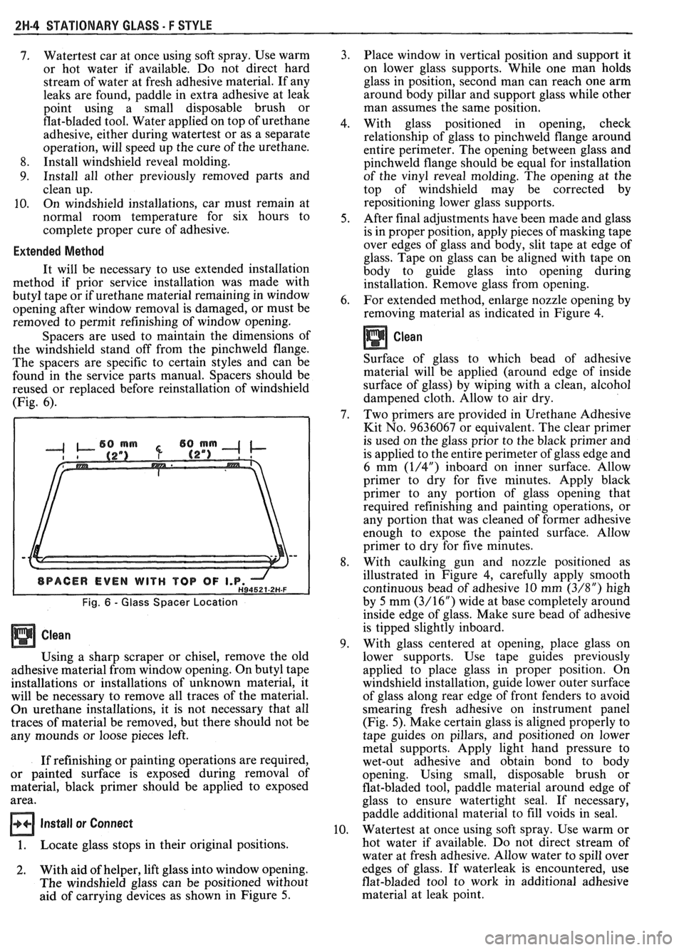
(Fig. 6).
Fig. 6 - Glass Spacer Location
Using a sharp scraper or chisel, remove the old
adhesive material from window opening. On butyl tape
installations or installations of unknown material, it
will be necessary to remove all traces of the material.
On urethane installations, it is not necessary that all
traces of material be removed, but there should not be
any mounds or loose pieces left.
If refinishing or painting operations are required,
or painted surface is exposed during removal of
material, black primer should be applied to exposed
area.
Install or Connect
1. Locate glass stops in their original positions.
2. With aid of helper, lift glass into window opening.
The windshield glass can be positioned without
aid of carrying devices as shown in Figure 5. Place window
in vertical position and support it
on lower glass supports. While one man holds
glass in position, second man can reach one arm
around body pillar and support glass while other
man assumes the same position.
With glass positioned in opening, check
relationship of glass to pinchweld flange around
entire perimeter. The opening between glass and
pinchweld flange should be equal for installation
of the vinyl reveal molding. The opening at the
top of windshield may be corrected by
repositioning lower glass supports.
After final adjustments have been made and glass
is in proper position, apply pieces of masking tape
over edges of glass and body, slit tape at edge of
glass. Tape on glass can be aligned with tape on
body to guide glass into opening during
installation. Remove glass from opening.
For extended method, enlarge nozzle opening by
removing material as indicated in Figure
4.
Clean
Surface of glass to which bead of adhesive
material will be applied (around edge of inside
surface of glass) by wiping with a clean, alcohol
dampened cloth. Allow to air dry.
Two primers are provided in Urethane Adhesive
Kit No. 9636067 or equivalent. The clear primer
is used on the glass prior to the black primer and
is applied to the entire perimeter of glass edge and
6 mm
(1/4") inboard on inner surface. Allow
primer to dry for five minutes. Apply black
primer to any portion of glass opening that
required refinishing and painting operations, or
any portion that was cleaned of former adhesive
enough to expose the painted surface. Allow
primer to dry for five minutes.
With caulking gun and nozzle positioned as
illustrated in Figure 4, carefully apply smooth
continuous bead of adhesive 10 mm
(3/8") high
by 5 mm
(3/16") wide at base completely around
inside edge of glass. Make sure bead of adhesive
is tipped slightly inboard.
With glass centered at opening, place glass on
lower supports. Use tape guides previously
applied to place glass in proper position. On
windshield installation, guide lower outer surface
of glass along rear edge of front fenders to avoid
smearing fresh adhesive on instrument panel
(Fig. 5). Make certain glass is aligned properly to
tape guides on pillars, and positioned on lower
metal supports. Apply light hand pressure to
wet-out adhesive and obtain bond to body
opening. Using small, disposable brush or
flat-bladed tool, paddle material around edge of
glass to ensure watertight seal. If necessary,
paddle additional material to fill voids in seal.
Watertest at once using soft spray. Use warm or
hot water if available. Do not direct stream of
water at fresh adhesive. Allow water to spill over
edges of glass. If waterleak is encountered, use
flat-bladed tool to work in additional adhesive
material at leak point.
Page 1703 of 1825
2H-6 STATIONARY GLASS - F STYLE
all traces of factory installed adhesive must be
removed prior to reinstallation.
5. Wipe sanded mirror support with clean paper
towel saturated with alcohol and allow to dry.
6. Follow directions on manufacturer's kit to
prepare
rearview mirror support prior to
installation on glass.
7. Properly position support to its premarked
location, with rounded end pointed upward; press
support against glass for 30 to 60 seconds,
exerting steady pressure against glass. After five
minutes, any excess adhesive may be removed
with an alcohol moistened paper towel or glass
cleaning solution.
8. Reinstall mirror
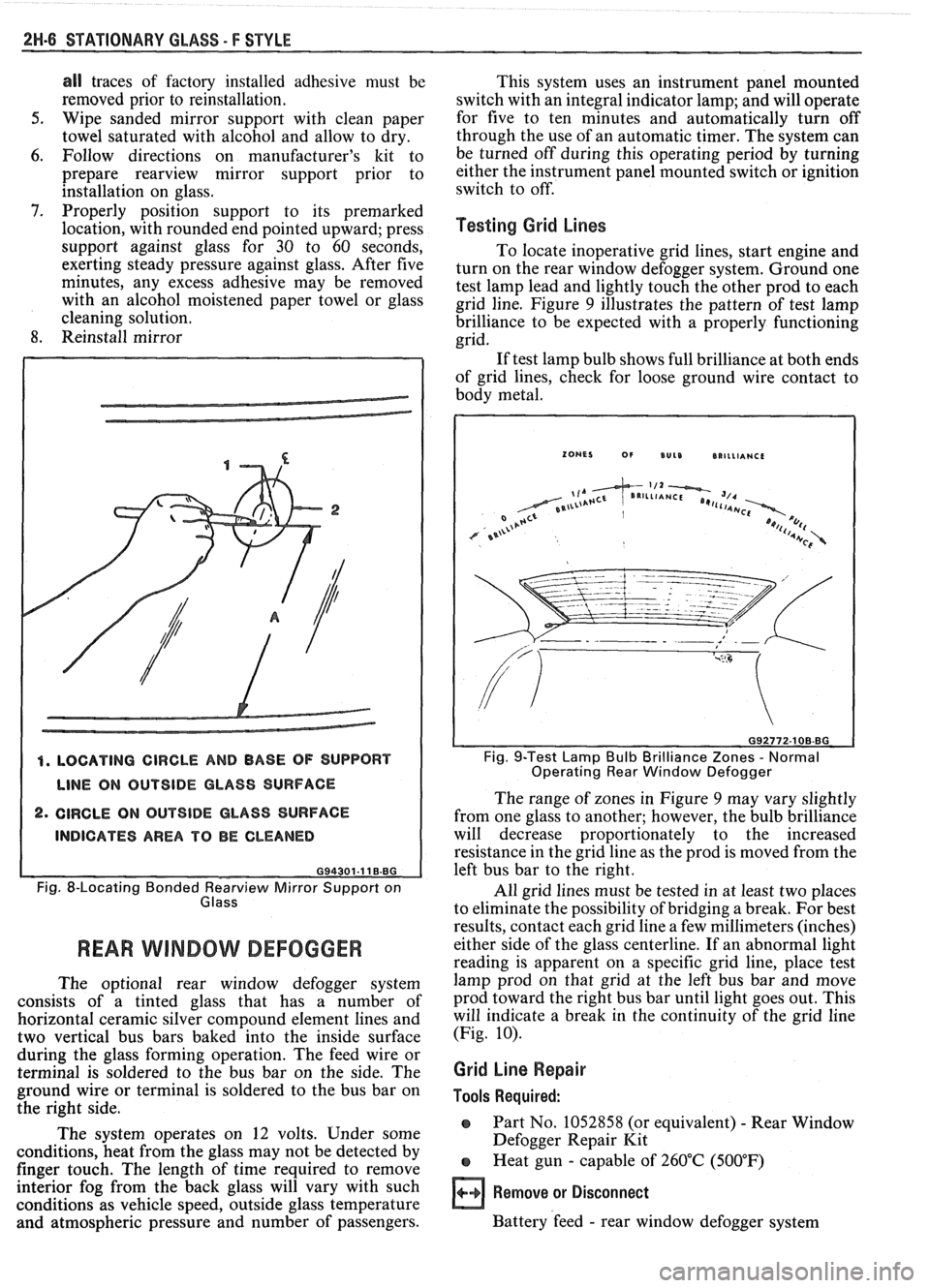
4. LOCATING CIRCLE AND BASE OF SUPPORT
LINE ON OUTSIDE GLASS SURFACE
2. CIRCLE ON OUTSIDE GLASS SURFACE
INDICATES AREA TO BE CLEANED
G94301-11 B.BG
Fig. 8-Locating Bonded earv view Mirror Support on
Glass
REAR WlMBOW DEFOGGER
The optional rear window defogger system
consists of a tinted glass that has a number of
horizontal ceramic silver compound element lines and
two vertical bus bars baked into the inside surface
during the glass forming operation. The feed wire or
terminal is soldered to the bus bar on the side. The
ground wire or terminal is soldered to the bus bar on
the right side.
The system operates on 12 volts. Under some
conditions, heat from the glass may not be detected by
finger touch. The length of time required to remove
interior fog from the back glass will vary with such
conditions as vehicle speed, outside glass temperature
and atmospheric pressure and number of passengers. This
system uses an instrument panel mounted
switch with an integral indicator lamp; and will operate
for five to ten minutes and automatically turn off
through the use of an automatic timer. The system can
be turned off during this operating period by turning
either the instrument panel mounted switch or ignition
switch to off.
Testing Grid Lines
To locate inoperative grid lines, start engine and
turn on the rear window defogger system. Ground one
test lamp lead and lightly touch the other prod to each
grid line. Figure
9 illustrates the pattern of test lamp
brilliance to be expected with a properly functioning
grid.
If test lamp bulb shows full brilliance at both ends
of grid lines, check for loose ground wire contact to
body metal.
Fig. 9-Test Lamp Bulb Brilliance Zones - Normal
Operating Rear Window Defogger
The range of zones in Figure 9 may vary slightly
from one glass to another; however, the bulb brilliance
will decrease proportionately to the increased
resistance in the grid line as the prod is moved from the
left bus bar to the right.
All grid lines must be tested in at least two places
to eliminate the possibility of bridging a break. For best
results, contact each grid line a few millimeters (inches)
either side of the glass centerline. If an abnormal light
reading is apparent on a specific grid line, place test
lamp prod on that grid at the left bus bar and move
prod toward the right bus bar until light goes out. This
will indicate a break in the continuity of the grid line
(Fig.
10).
Grid Line Repair
Tools Required:
o Part No. 1052858 (or equivalent) - Rear Window
Defogger Repair Kit
e Heat gun - capable of 260°C (500°F)
Remove or Disconnect
Battery 'feed - rear window defogger system
Page 1706 of 1825
UNDERBODY-F STYLE 3H-1
SECTION 3H
UNDERBODY
CONTENTS
General Body Construction .......................................................................................................... 3H- 1
Alignment Checking ................................................................................................................ 3H- I
Floor Pan Insulators ...................... .. ........................................................................................ 3H- 1
Floor Carpets ................................................................................................................................. 3H-2
metric-to-English dimensional conversion data.
Dimensions to gage holes are measured to dead center
GENERAL BODY CONSTRUCTION of the holes and flush to adjacent surface metal unless
Information in this section pertains to unitized otherwise specified.
body construction which
incorporates integral front
and rear frame side rails. FLOOR PAN INSULATORS
Consideration must be given when checking
underbody dimensions. The engine front suspension
lower control arms are supported by a cross member.
The cross member, in turn, is bolted to the body at six
locations
-- three on each side of the engine front
compartment lower rails. Mounting provisions for the
front suspension system are shared by chassis
components (suspension lower control arms and cross
member) and body components (engine compartment
side panels). The suspension strut towers must be
dimensionally correct in relation to the remainder of
the underbody in order to maintain specified
suspension strut and
castedcamber angles.
Since the individual underbody components also
contribute directly to the overall strength of the body,
it is essential that proper welding techniques be
observed during service repair operations. The
underbody components should be properly sealed and
rustproofed whenever body repair operations destroy
or damage the original sealing and rustproofing. When
rustproofing critical underbody components, it is
essential that a good quality type of air dry primer be
used (such as corrosion resistant chromate or
equivalent material). It is not advisable to use
combination type primer-surfacers.
ALIGNMENT CHECKING
An accurate method of determining the
alignment of the underbody utilizes a measuring tram
gage. The tram gage set required to perform the
recommended measuring checks must include a
vertical pointer capable of reaching 914 mm (36").
Two types of measurements can be made with
a
tram gage: direct point-to-point measurements and
measurements calculated on a horizontal
vlane (datum
line) parallel to the underbody. In the
latter case, the
vertical pointers must be set as specified for each point
to be measured (Fig. 3-1).
Point-to-point measurements are generally taken
only on engine compartment components (Fig. 3-2)
and simply require the vertical pointers to be equally
set.
Figure #3-3 describes the alphabetically
identified points of measurement. Figure 3-4 provides Floor
pan insulators have been designed for the
higher floor pan temperatures that result from the use
of the catalytic converter in the exhaust system.
Therefore, when servicing a vehicle in the field, it is
essential that any insulators that may have been
disturbed or removed be reinstalled in the original
sequence and location. Also, if it becomes necessary to
replace an insulator, the material specified for that
particular location on the floor pan must be used. The
types of materials are listed below. Items 1 and
2 are
rolled stock and are ordered by linear foot and cut to
fit.
1. Insulator floor pan
(cerra blanket thermal) -
consists of 10 mm (3/8") thick aluminum silica
(type 1).
2. Insulator floor pan (amberlite) - consists of 10
mm
(3/8") thick resinated fibers (type 2).
3. Insulator floor pan sheet (phenolic bonded fiber
glass)
305 mm x 457 mm (12" x 18") cut to size,
(type 3).
All of the above materials must meet
Motor Vehicle Safety Standard No. 302 for
flammability.
When servicing or replacing interior insulators,
the following instructions must be observed:
1. Insulators must be installed in the original
position and sequence. Pieces should be butted
together in order to avoid gapping or
overlapping.
2. If it is necessary to replace an insulator, the
specified material must be used.
3. Use original
part to determine the amount of
replacement material required and as a template
for cutting and fitting the new piece to the floor
pan.
4. When installing insulator, do not enlarge cutouts
or holes that are used for the attachment of
interior components such as seats or seat belts.
5. Cross body harnesses for interior components
such as power seats, lap belt warning light and
buzzer or rear speakers must be routed over the
floor pan insulators in the original location and
clipped in place.
Page 1722 of 1825
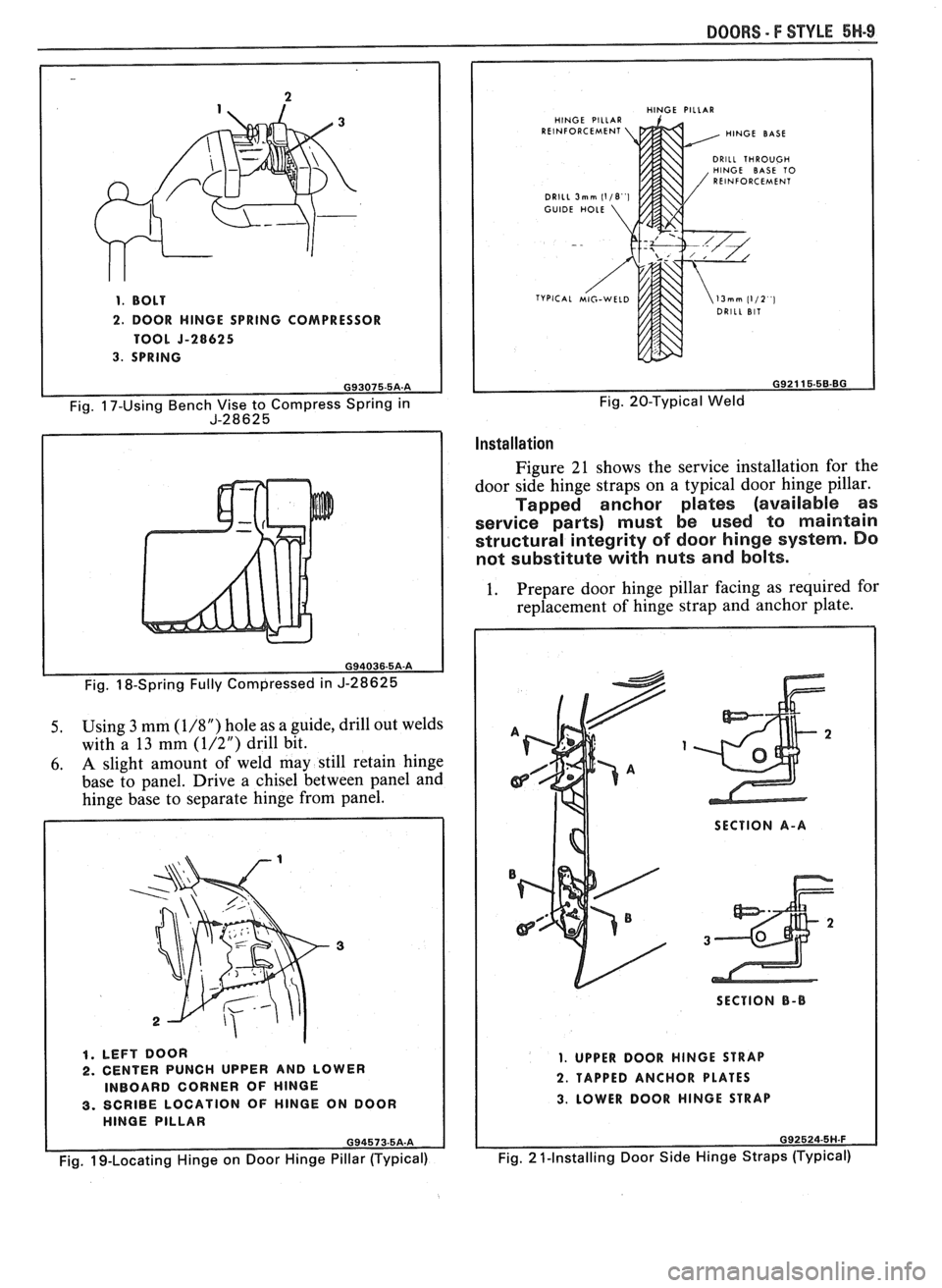
1. BOLT
2. DOOR HlNGE SPRING COMPRESSOR
TOOL
5-28625
3. SPRING
Fig. 18-Spring Fully Compressed in J-28625
5. Using 3 mm (1/8") hole as a guide, drill out welds
with a 13 mm
(1/2") drill bit.
6. A slight amount of weld may still retain hinge
base to panel. Drive a chisel between panel and
hinge base to separate hinge from panel.
1. LEFT DOOR 2. CENTER PUNCH UPPER AND LOWER
INBOARD CORNER OF HlNGE
3. SCRIBE LOCATION OF HlNGE ON DOOR
HlNGE PILLAR
Fig. 19-Locating Hinge on Door Hinge Pillar (Typical)
BOORS - F STYLE 6H.9
HlNGE PILLAR
HlNGE PILLAR
REINFORCEMENT HlNGE BASE
DRILL THROUGH
HlNGE BASE TO
REINFORCEMENT
DRILL
3mm (118 1 GUIDE HOLE
Fig. 20-Typical Weld
Installation
Figure 21 shows the service installation for the
door side hinge straps on a typical door hinge pillar.
Tapped anchor plates (available as
service parts) must be used to maintain
structural integrity of door hinge system. Do
not substitute with nuts and bolts.
1. Prepare
door hinge pillar facing as required for
replacement of hinge strap and anchor plate.
SECTION A-A
SECTION
8-B
1. UPPER DOOR HINGE STRAP
2. TAPPED ANCHOR PLATES
3. LOWER DOOR HlNGE STRAP
092524-5H.F
Fig. 2 1-Installing Door Side Hinge Straps (Typical)
Page 1730 of 1825
DOORS - F STYLE 5W.17
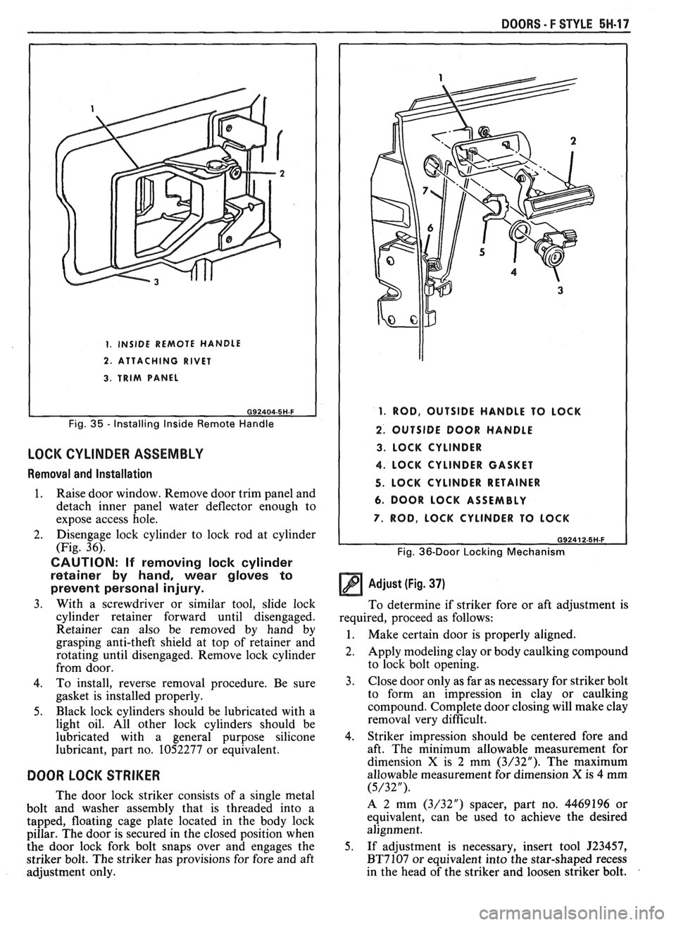
1. INSIDE REMOTE HANDLE
2. ATTACHING RIVET
3. TRIM PANEL
Fig. 35 - Installing Inside Remote Handle
LOCK CYLINDER ASSEMBLY
Removal and Installation
1. Raise door window. Remove door trim panel and
detach inner panel water deflector enough to
expose access hole.
2. Disengage lock cylinder
to lock rod at cylinder
(Fig. 36).
CAUTION: If removing lock cylinder
retainer by hand, wear gloves to
prevent personal injury.
3. With a screwdriver or similar tool, slide lock
cylinder retainer forward until disengaged.
Retainer can also be removed by hand by
grasping anti-theft shield at top of retainer and
rotating until disengaged. Remove lock cylinder
from door.
4. To install, reverse removal procedure. Be sure
gasket is installed properly.
5. Black lock cylinders should be lubricated with a
light oil. All other lock cylinders should be
lubricated with a general purpose silicone
lubricant, part no. 1052277 or equivalent.
DOOR LOCK STRIKER
The door lock striker consists of a single metal
bolt and washer assembly that is threaded into a
tapped, floating cage plate located in the body lock
pillar. The door is secured in the closed position when
the door lock fork bolt snaps over and engages the
striker bolt. The striker has provisions for fore and aft
adjustment only.
1. ROD, OUTSIDE HANDLE TO LOCK
2. OUTSIDE DOOR HANDLE
3. LOCK CYLINDER
4. LOCK CYLINDER GASKET
5. LOCK CYLINDER RETAINER
6. DOOR LOCK ASSEMBLY
7. ROD, LOCK CYLINDER TO LOCK
G92412-5H.F
Fig. 36-Door Locking Mechanism
Adjust (Fig. 37)
To determine if striker fore or aft adjustment is
required, proceed as follows:
1. Make certain door is properly aligned.
2. Apply modeling clay or body caulking compound
to lock bolt opening.
3. Close
door only as far as necessary for striker bolt
to form an impression in clay or caulking
compound. Complete door closing will make clay
removal very difficult.
4. Striker impression should be centered fore and
aft. The minimum allowable measurement for
dimension
X is 2 mm (3/32"). The maximum
allowable measurement for dimension
X is 4 mm
(5/32").
A 2 mm (3/32") spacer, part no. 4469196 or
equivalent, can be used to achieve the desired
alignment.
5. If adjustment is necessary, insert tool
J23457,
BT7107 or equivalent into the star-shaped recess
in the head of the striker and loosen striker bolt.
Page 1732 of 1825
DOORS - F STYLE 5H-99
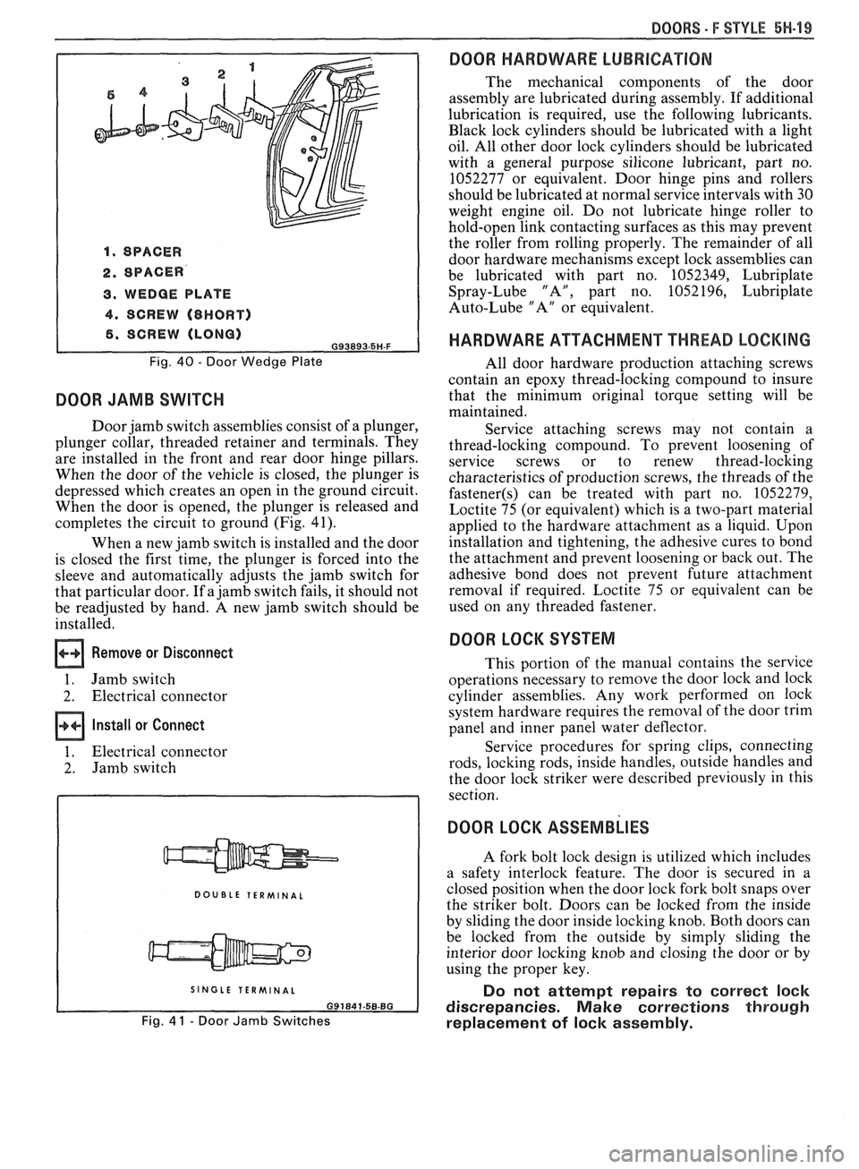
1. SPACER
2. SPACER
3. WEDGE PLATE
4. SCREW (8HORT)
6. SCREW (LONG) G93893.5H-F
Fig. 40 - Door Wedge Plate
DOOR JAMB SWITCH
Door jamb switch assemblies consist of a plunger,
plunger collar, threaded retainer and terminals. They
are installed in the front and rear door hinge pillars.
When the door of the vehicle is closed, the plunger is
depressed which creates an open in the ground circuit.
When the door is opened, the plunger is released and
completes the circuit to ground (Fig. 41).
When a new jamb switch is installed and the door
is closed the first time, the plunger is forced into the
sleeve and automatically adjusts the jamb switch for
that particular door. If a jamb switch fails, it should not
be readjusted by hand. A new jamb switch should be
installed.
Remove or Disconnect
1. Jamb switch
2. Electrical connector
Install or Connect
1. Electrical connector
2. Jamb switch
DOUBLE TERMINAL
I SINGLE TERMINAL I
Fig. 4 1 - Door Jamb Switches
DOOR HARDWARE LUBRICATION
The mechanical components of the door
assembly are lubricated during assembly. If additional
lubrication is required, use the following lubricants.
Black lock cylinders should be lubricated with a light
oil. All other door lock cylinders should be lubricated
with a general purpose silicone lubricant, part no.
1052277 or equivalent. Door hinge pins and rollers
should be lubricated at normal service intervals with 30
weight engine oil. Do not lubricate hinge roller to
hold-open link contacting surfaces as this may prevent
the roller from rolling properly. The remainder of all
door hardware mechanisms except lock assemblies can
be lubricated with part no. 1052349, Lubriplate
Spray-Lube "A", part no. 1052196, Lubriplate
Auto-Lube "A" or equivalent.
HARDWARE ATTACHMENT THREAD LOCKING
All door hardware production attaching screws
contain an epoxy thread-locking compound to insure
that the minimum original torque setting will be
maintained.
Service attaching screws may not contain a
thread-locking compound. To prevent loosening of
service screws or to renew thread-locking
characteristics of production screws, the threads of the
fastener(s) can be treated with part no. 1052279,
Loctite 75 (or equivalent) which is a two-part material
applied to the hardware attachment as a liquid. Upon
installation and tightening, the adhesive cures to bond
the attachment and prevent loosening or back out. The
adhesive bond does not prevent future attachment
removal if required. Loctite 75 or equivalent can be
used on any threaded fastener.
DOOR LOCK SYSTEM
This portion of the manual contains the service
operations necessary to remove the door lock and lock
cylinder assemblies. Any work performed on lock
system hardware requires the removal of the door trim
panel and inner panel water deflector.
Service procedures for spring clips, connecting
rods, locking rods, inside handles, outside handles and
the door lock striker were described previously in this
section.
DOOR LOCK ASSEMBLIES
A fork bolt lock design is utilized which includes
a safety interlock feature. The door is secured in a
closed position when the door lock fork bolt snaps over
the striker bolt. Doors can be locked from the inside
by sliding the door inside locking knob. Both doors can
be locked from the outside by simply sliding the
interior door locking knob and closing the door or by
using the proper key.
Do not attempt repairs to correct lock
discrepancies. Make corrections through
replacement of lock assembly.
Page 1745 of 1825
71.1-2 REAR END - F STYLE
dampened slightly with oil-free naphtha;
then remove tape strips.
COMPARTMENT LIFT WINDOW MOLDING
Refinishing
1. Mask off area(s) adjacent to molding(s).
2. Clean with Ditzler's DX-440 wax and grease
removing solvent or equivalent.
3. Sand with
#400 grit wet or dry sandpaper.
4. Clean
with wax and grease removing solvent.
5. Prime with Ditzler's
epoxy chromate primer DP
40/40 1 or equivalent.
6. Sand with
#500 grit wet or dry sandpaper.
7. Clean with wax and grease removing solvent.
8. Top
coat with flat black acrylic lacquer.
9. Remove masking tape.
When using any of the listed materials, follow the
manufacturer's label directions for application
procedures and drying time.
Removal
CAUTION: When working with glass
assemblies, the use of personal
protection items such as safety
glasses and work gloves is
recommended to minimize the chance
of personal injury should the glass
break.
1. Remove compartment lift window from body, as
described later in this section, and with the aid of
a helper, place upside down on a protected work
surface.
2. Remove upper hinges.
3. Remove screws retaining moldings to panel.
CAUTION: Perform the urethane
burn-out operation in a well ventilated
area and avoid direct inhalation of the
fumes being emitted as these fumes
may be hazardous.
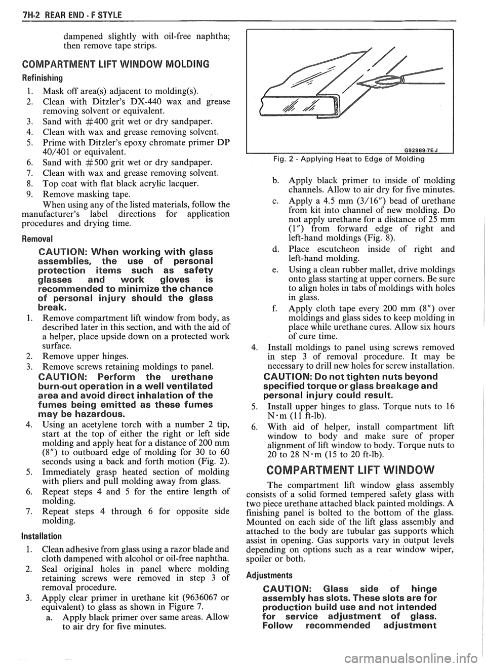
4. Using an acetylene torch with a number 2 tip,
start at the top of either the right or left side
molding and apply heat for a distance of 200 mm
(8") to outboard edge of molding for 30 to 60
seconds using a back and forth motion (Fig. 2).
5. Immediately grasp heated section of molding
with pliers and pull molding away from glass.
6. Repeat steps
4 and 5 for the entire length of
molding.
7. Repeat steps 4 through 6 for opposite side
molding.
Installation
1. Clean adhesive from glass using a razor blade and
cloth dampened with alcohol or oil-free naphtha.
2. Seal original holes in panel where molding
retaining screws were removed in step 3 of
removal procedure.
3. Apply clear primer in urethane kit (9636067 or
equivalent) to glass as shown in Figure 7.
a. Apply
black primer over same areas. Allow
to air dry for five minutes.
Fig. 2 -Applying Heat to Edge of Molding
b. Apply
black primer to inside of molding
channels. Allow to air dry for five minutes.
c. Apply a 4.5 mm
(3/16") bead of urethane
from kit into channel of new molding. Do
not apply urethane for a distance of
25 mm
(1") from forward edge of right and
left-hand moldings (Fig. 8).
d. Place escutcheon inside of right and
left-hand molding.
e. Using a
clean rubber mallet, drive moldings
onto glass starting at upper corners. Be sure
to align holes in tabs of moldings with holes
in glass.
f. Apply cloth tape every 200 mm (8") over
moldings and glass sides to keep molding in
place while urethane cures. Allow six hours
of cure time.
4. Install moldings to panel using screws removed
in step 3 of removal procedure. It may be
necessary to drill new holes for screw installation.
CAUTION: Do not tighten nuts beyond
specified torque or glass breakage and
personal injury could result.
5. Install
upper hinges to glass. Torque nuts to 16
N-m (1 1 ft-lb).
6. With aid of helper, install compartment lift
window to body and make sure of proper
alignment of lift window to body. Torque nuts to
20 to 28
N-m (15 to 20 ft-lb).
COMPARTMENT LIFT WINDOW
The compartment lift window glass assembly
consists of a solid formed tempered safety glass with
two piece urethane attached black painted moldings. A
finishing panel is bolted to the bottom of the glass.
Mounted on each side of the lift glass assembly and
attached to the body are tubular gas supports which
assist in opening. Gas supports vary in output levels
depending on options such as a rear window wiper,
spoiler or both.
Adjustments
CAUTION: Glass side of hinge
assembly has slots. These slots are for
production build use and not intended
for service adjustment of
glass.
Follow recommended adjustment