Page 1556 of 1825

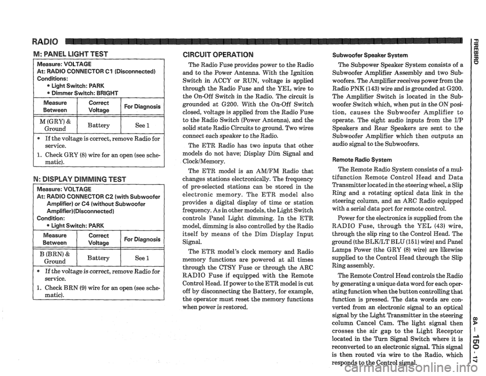
M: WNEL LIGHT TEST GlRGUlT OPERATION Subwoofer Speaker System
TOR 61 (Disconnected)
If the voltage is correct, remove Radio for
N: DISPLAY DIMMING TEST
TOW 62 (with Subwoofer
The Radio Fuse provides power to the Radio
and to the Power Antenna. With the Ignition
Switch in ACCY or RUN, voltage is applied
through the Radio Fuse and the
UEL wire to
the On-Off Switch in the Radio. The circuit is
grounded at 6200. With the On-Off Switch
closed, voltage is applied from the Radio Fuse
to the Radio Switch (Power Antenna), and the
solid state Radio Circuits to ground. Two wires
connect each speaker to the Radio.
The ETR Radio has two inputs that other
models do not have; Display Dim Signal and
ClocklMemory.
The ETR model is an AMIFM Radio that
changes stations electronically. The frequency
of pre-selected stations can be stored
in the
electronic memory. The ETR model also
provides a digital display of time or station
frequency. As in other models, the Light Switch
controls Panel Light dimming. In the
ETR
model, g is also controlled by the Radio
itself by means of the Dim Display Input
Signal.
The ETR model's clock memory and Radio
memory functions are powered at all times
through the CTSY Fuse or through the ARC
RADIO Fuse if equipped with the Remote
Control Head. If power to the ETR model is cut
off by disconnecting the Battery, for example,
the operator must reset the memory functions
when power is restored. The
Subpower Speaker
System consists of a
Subwoofer Amplifier Assembly and two Sub-
woofers. The Amplifier receives power from the
Radio PNK
(143) wire and is grounded at 6200.
The Amplifier Switch is located in the
Sub-
woofer Switch which, when put in the ON posi-
tion, causes the Subwoofer Amplifier to
operate. The eight audio inputs from the
I/P
Speakers and Rear Speakers are sent to the
Subwoofer Amplifier which then outputs an
audio signal to the Subwoofers.
Remote Radio System
The Remote Radio System consists of a mul-
tifunction Remote Control
Head and Data
Transmitter located in the steering wheel, a Slip
Ring and a rotating optical data link in the
steering
colurnn, and an ARC Radio equipped
with a serial data port for remote control.
Power for the electronics is supplied from the
RADIO Fuse, through the
YEL (43) wire,
through the slip ring to the Control Head. The
ground (the
BLKLT BLU (15 1) wire) and Pand
Larnps Power (the GRY (8) wire) are Likewise
supplied to the Control Head through the Slip
Ring assembly.
The Remote Control Head controls the Radio
by generating a unique data word for each oper-
ating function when the button controlling that
function is pressed. The data words are con-
verted from an electronic signal to an optical
signal by the Light Transmitter in the steering
column Cancel Cam. The light signal then
crosses the air gap to the Light Receptor
located in the
Turn Signal Switch where it is
reconverted to
an electronic signal. This signal
is then routed via wire to the Radio, which
responds to the Control signal.
Page 1558 of 1825

POWER ANTENNA
TROUBLESHOOTING HINTS
r Try the following checks before doing the
System Check.
1. Check the Radio Fuse by turning the Radio
ON and noting that the display lights come
on.
2. Check the CTSY Fuse by operating the
Cigar Lighter.
3. Power Antenna goes up or down part way
- Check Power Antenna mast for bent con-
dition or dirt. If
mast is dirty and/or bent,
straighten the mast and clean off the dirt.
Lube with light oil and check operation. If
the mast is straight and clean, replace the
Antenna Motor.
c Go to System Check for a guide to normal
operation.
e Go to System Diagnosis for diagnostic tests.
SYSTEM CHECK
a Use the System Check Table as a guide to
normal operation.
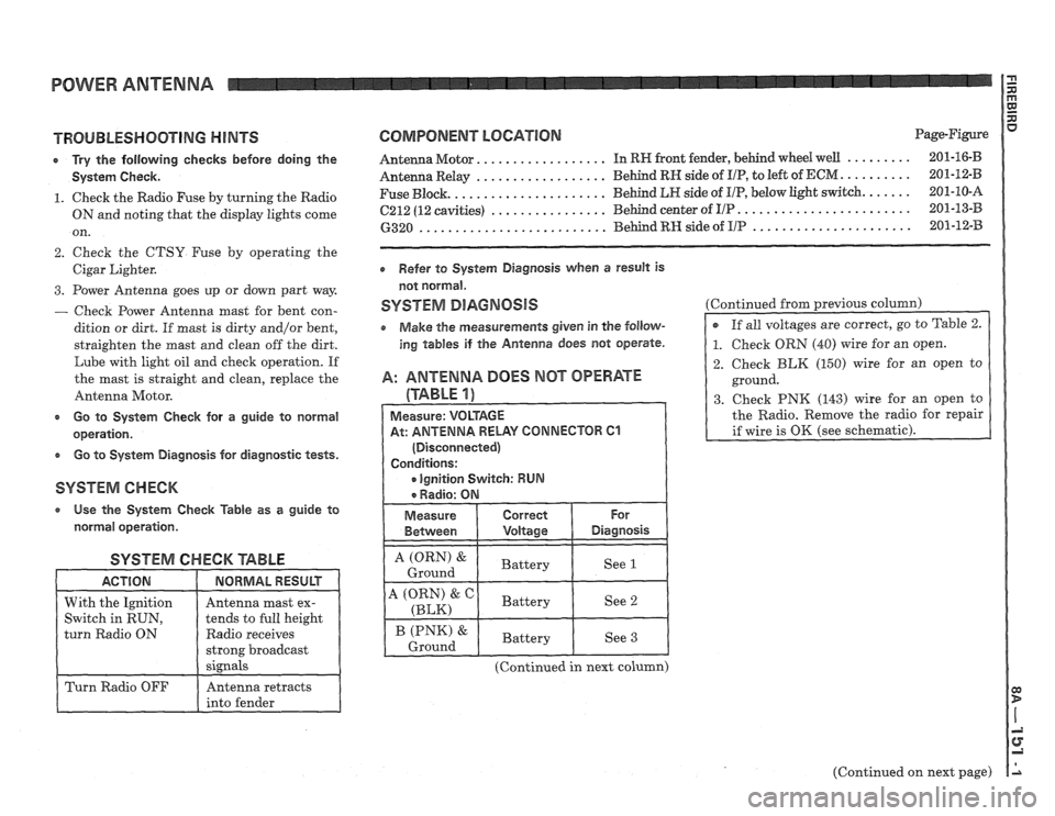
SYSTEM CHECK '6ABLE
Radio receives
COMPONENT LOCATION Page-Figure
................. ......... Antenna Motor. In RW front fender, behind wheel well 201-16-B
.................. .......... Antenna Relay Behind RN side of I/P, to
left of ECM 201-12-B
..................... ...... Fuse Block. Behind LR side
of UP, below light switch. 201-10-A
........................ ................ 6212 (12 cavities) Behind center of I/P 201-13-B
...................... .......................... 6320 Behind RH side of IIP 201-12-33
Refer to System Diagnosis when a result is
not normal.
SYSTEM DlAGNOSlS
o Make the measurements given in the follow-
ing tables if the Antenna does not operate.
A: ANTENNA DOES MOT OPERATE
(TABLE 1)
At: ANTENNA RELAY CONNECTOR 61
(Continued in next column) Continued
from previous
column)
2. Check BLK (150) wire for an open to
ground.
3. Check PNK (143) wire for an open to
the Radio. Remove the radio for repair
(Continued on next page)
Page 1576 of 1825
COMPONENT LOCATION VIEWS
Figure A - LH Side Of Engine Compartment
FOG
LIGHT
61 03 HEADLIGHT
I DOOR
RE LAY
dr
Figure B - LH Front Corner Of Engine Comlpartlnent Figure C - LH Rear Corner Of Engine Compartment RH HATCH
Figure
D - RH Side Of Cargo Compartment
CONNECTOR
Figure E - LH Side Of Windshield Header
Page 1577 of 1825
COMPONENT LOCATION VlEWS I E!
BRAKE
HEADLIGHT FLUID
DOOR MODULE - LEVEL
WASHER
FLUID LEVEL
RN HEADLIGHT LOW COOLANT
DOOR MOTOR PROBE CONNECTOR
CONNECTOR
12H3.4
Figure B - Behind RN Front Wheel Well
RELEASE
SOLENOlD
CONNECTOR
Figure C
- LH Rear Corner Of Cargo Compartment
Page 1581 of 1825
HARNESS CONNECTOR FACES I
BULKHEAD CONNECTOR, ClOO
ENGINE HARNESS CONNECTOR
(REMOVED FROM
C100)
Cl00 TERM1 NAL VIEW
(AS MOUNTED ON COWL) FRONT
LIGHT
I-IARNESS CONNECTOR
(REMOVED FROM
C100)
Page 1583 of 1825
HARNESS CONNECTOR FACES
JUNCTION BLOCK, 6238
POWER DOOR LOCKS
POWER FEED FROM
IIP
HARNESS; CIRCUIT
40 AND 60
POWER REMOTE
MIRRORS
LUMBAR SUPPORT
CARGO
COMPARTMENT LIGHT CONNECTORS
WITHIN EACH
BRACKET CAN BE
INTERCHANGED
BLK POWER
FEED FROM
FUSE;
CIRCUIT
76
POWER WINDOWS
Page 1588 of 1825
HARNESS CONNECTOR FACES
BURN-OFF RELAY, SEE AUXILIARY
COOLANT FAN RELAY
BLK
CLUTCH START SWITCH
V00491.1
COOLANT FAN RELAY, SEE
AUXILIARY COOLANT FAN RELAY
CRUISE CONTROL SERVO
V00459 0
BLK
CONVENIENCE CENTER
V00275 1
CRUISE CONTROL MODULE
V00286 0
WHT
DEFOGGER CONTROL
V00569 0
BLK
DEFOGGER
TIMER RELAY
V0056 1 0
WHT
DOME LIGHT
V00570.0
Page 1590 of 1825
FOG LIGHT SWITCH,
SEE DEFOGGER CONTROL
WHY
FRONT POWER WINDOW
SWITCH (LH)
V00487 1
BLU
FRONT POWER
WINDOW SWITCH (RH)
V00571 0
FUEL PUMP RELAY, SEE A/C
COMPRESSOR CONTROL RELAY
BRN
FUEL PUMP SWITCH
(V8 VIM F) (V8 VIN 8)
V00?49 0
GEAR SELECTOR SWITCH
V00541 1
GENERATOR
V00176 0
C1 BLK CZ BLK
HATCH COWTACT ASSEMBLY
V00235.0
C1 BLK CP BLK
HEADLIGHT DOOR MODULE
V00512.0