1988 PONTIAC FIERO transmission
[x] Cancel search: transmissionPage 376 of 1825
2.8 LITER V-6 6A2-25
Fitting
1. Select rings comparable in size to the piston being
used.
2. Slip
the compression ring in the cylinder bore;
then press the ring down into the cylinder bore
about 6mm above ring travel. Be sure ring is
square with cylinder wall.
3. Measure the space or gap between the ends of the
ring with a feeler gage (Figure
6A2-33).
4. If
the gap between the ends of the ring is below
specifications, remove the ring and try another
for fit.
5. Fit each compression ring to the cylinder in
which it is going to be used.
6. If the pistons have not been cleaned and inspected
as previously outlined, do so.
7. Slip the outer surface of the top and second
compression ring into the respective piston ring
groove and roll the ring entirely around the
groove (Figure
6A2-34). If binding occurs at any
point, the cause should be determined. If there is
a ring groove, remove by dressing with a fine cut
file. If the binding is caused by a distorted ring,
check a new ring.
Installation
1. Install oil ring spacer in groove being sure ends
are butted and not overlapped.
2. Hold
spacer ends butted and install lower steel oil
ring rail.
3. Install upper
steel oil ring rail with gap staggered.
4. Flex
the oil ring assembly to make sure ring is
free. If binding occurs, the cause should be
detemined. If caused by ring groove, remove by
dressing groove with a fine cut file. If binding is
caused by a distorted ring, check a new ring.
5. Install second compression ring. Stagger gap
from other rings.
6. Install top compression ring with gap properly
located.
ENGINE ASSEMBLY
Removal
Disconnect battery.
Remove air cleaner.
Remove hood. Drain radiator.
Remove lower radiator hose.
Remove upper fan shroud.
Remove upper radiator hose and coolant
recovery hose.
Remove transmission cooler lines. Remove radiator.
Remove fan assembly.
Remove heater hoses.
Disconnect carburetor linkage, includes cruise
control detent cable.
Remove vacuum brake booster line.
Remove distributor cap and lay wiring aside.
Disconnect necessary wires and hoses.
Remove power steering pump and lay aside. Raise
vehicle.
Remove exhaust pipes at exhaust manifold.
Remove dust cover.
Remove converter bolts.
Disconnect starter wires.
Remove bell housing bolts.
Remove motor mount through bolts.
Disconnect fuel lines at fuel pump.
Lower vehicle. Support transmission.
Remove
A.I.R./Converter pipes bracket.
Remove engine, include removing wire from
bracket at rear left of engine.
Installation
Position engine assembly in vehicle.
Attach motor mount to engine brackets and
lower engine in place.
Remove engine lifting device.
Remove transmission floor jack.
Raise vehicle on hoist.
Install mount "through" bolts. Torque to
specifications.
Install bell housing bolts. Torque to
specifications.
On vehicles with automatic transmission, install
converter to flywheel attaching bolts. Torque to
specifications.
Install flywheel splash shield of conveter housing
cover as applicable. Torque attaching bolts to
specifications.
Install starter wires.
Connect fuel lines.
Connect exhaust pipe at manifold.
Lower vehicle on hoist.
Reinstall power steering pump, if so equipped.
Connect necessary wires and hoses.
Install radiator and fan shroud and reconnect
radiator and heater hoses.
Fill cooling system.
Fill crankcase with oil. See owner's manual for
specifications.
Install air cleaner.
Install hood.
Connect battery cables.
NOTICE: To avoid possible arcing of battery,
connect positive battery cable first.
22. Start engine, check for leaks and check timing.
CRANKSHAFT
The crankshaft can be removed while the engine
is dissasembled for overhaul, as previously outlined or
without complete disassembly.
Removal
1. With the engine removed from the vehicle,
remove the clutch assembly (if equipped) and
flywheel. Mount engine in stand and clamp
securely.
Page 384 of 1825
V-8 ENGINE BA3-5
ON-VEHICLE SERVICE
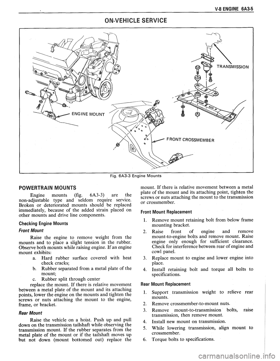
Fig. 6A3-3 Engine Mounts
POWERTRAIN MOUNTS
Engine mounts (fig. 6A3-3) are the
non-adjustable type and seldom require service.
Broken or deteriorated mounts should be replaced
immediately, because of the added strain placed on
other mounts and drive line components.
Checking Engine Mounts
Front Mount
Raise the engine to remove weight from the
mounts and to place a slight tension in the rubber.
Observe both mounts while raising engine. If an engine
mount exhibits:
a. Hard rubber surface covered with heat
check cracks;
b. Rubber separated from a metal plate of the
mount;
c. Rubber split through center
replace the mount. If there is relative movement
between a metal plate of the mount and its attaching
points, lower the engine on the mounts and tighten the
screws or nuts attaching the mount to the engine,
frame, or bracket.
Rear Mount
Raise the vehicle on a hoist. Push up and pull
down on the transmission tailshaft while observing the
transmission mount. If the rubber separates from the
metal plate of the mount or if the tailshaft moves up
but not down (mount bottomed out) replace the mount.
If there is relative movement between a metal
plate of the mount and its attaching point, tighten the
screws or nuts attaching the mount to the transmission
or crossmember.
Front Mount Replacement
1. Remove mount retaining bolt from below frame
mounting bracket.
2. Raise front of engine and remove
mount-to-engine bolts and remove mount. Raise
engine only enough for sufficient clearance.
Check for interference between rear of engine and
cowl panel.
3. Replace mount to engine and lower engine into
place.
4. Install retaining bolt and torque all bolts to
specifications.
Rear Mount Replacement I
1. Support transmission weight to relieve rear
mounts.
2. Remove crossmember-to-mount nuts.
3. Remove mount-to-transmission bolts, raise
transmission, then remove mount.
4. Install new mount on transmission.
5. While lowering transmission, align mount to
crossmember.
6. Torque bolts to specifications.
Page 397 of 1825
6A3-18 V-8 ENGINE
bore, remove remover and installer tool and
bearing from puller screw.
5. Remove remaining bearings (except front and
rear) in the same manner. It will be necessary to
index pilot in camshaft rear bearing to remove the
rear intermediate bearing.
6. Assemble remover
and installer tool on driver
handle and remove camshaft front and rear
bearings by driving towards center of cylinder
block.
lnstallation
The camshaft front and rear bearings should be
installed first. These bearings will act as guides for the
pilot and center the remaining bearings being pulled
into place.
1. Assemble remover
and installer tool on driver
handle and install camshaft front and rear
bearings by driving towards center of cylinder
block.
2. Using Tool Set J-6098, with nut then thrust
washer installed to end of threads, index pilot in
camshaft front bearing and install puller screw
through pilot.
3. Index camshaft bearing in bore (with oil hole
aligned as outlined below), then install remover
and installer tool on puller screw with shoulder
toward bearing.
e Number one cam bearing oil hole must be
positioned so that oil holes are equidistant
from 6 o'clock position.
e Number two through number four bearing
oil holes must be positioned at 5 o'clock
position (toward left side of engine and at a
position even with bottom of cylinder bore).
e Number five bearing oil hole must be in 12
o'clock position.
4. Using two wrenches, hold puller screw while
turning nut. After bearing has been pulled into
bore, remove the remover and installer tool from
puller screw and check alignment of oil hole in
camshaft bearing.
5. Install remaining bearings in the same manner. It
will be necessary to index pilot in the camshaft
rear bearing to install the rear intermediate
bearing.
6. Coat new camshaft rear plug O.D. with
# 1052080 sealant, or equivalent, and install
flush to 1/32"
(.80mm) deep.
OIL PAN
Removal
1. Disconnect battery negative cable.
2. Remove fan shroud.
3. Remove air cleaner and lay aside if equipped.
4. Remove distributor cap and lay aside.
5. Raise vehicle.
6. Drain crankcase.
7. Disconnect exhaust pipe at manifold.
8. Disconnect AIR pipe clamp.
9. Disconnect converter hanger bolts and allow
exhaust to hang down.
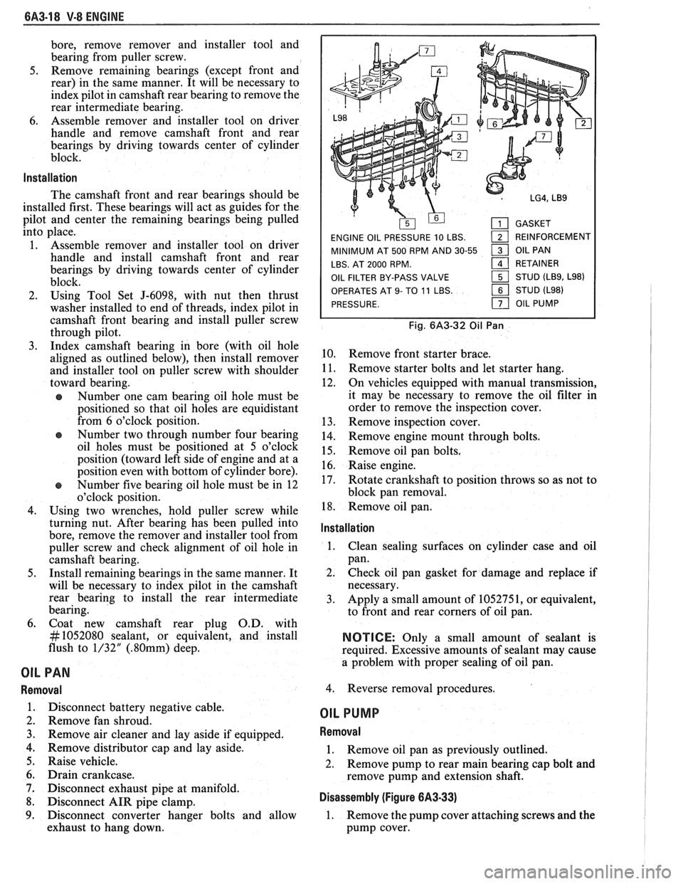
GASKET
ENGINE OIL PRESSURE 10 LBS.
1 REINFORCEMENT
MINIMUM AT 500 RPM AND 30-55
1 OIL PAN
LBS. AT 2000 RPM.
161 RETAINER
OIL FILTER BY-PASS VALVE STUD
(LB9, L98)
OPERATES
AT 9- TO 11 LBS. STUD (L98)
PRESSURE.
OIL PUMP
Fig. 6A3-32 Oil Pan
10. Remove front starter brace.
11. Remove starter bolts and let starter hang.
12. On vehicles equipped with manual transmission,
it may be necessary to remove the oil filter in
order to remove the inspection cover.
13. Remove inspection cover.
14. Remove engine mount through bolts.
15. Remove oil pan bolts.
16. Raise engine.
17. Rotate crankshaft to position throws so as not to
block pan removal.
18. Remove oil pan.
lnstallation
1.
Clean sealing surfaces on cylinder case and oil
pan.
2. Check oil pan gasket for damage and replace if
necessary.
3. Apply a small amount of 1052751, or equivalent,
to front and rear corners of oil pan.
NOTICE: Only a small amount of sealant is
required. Excessive amounts of sealant may cause
a problem with proper sealing of oil pan.
4. Reverse removal procedures.
OIL PUMP
Removal
1. Remove oil pan as previously outlined.
2. Remove pump to rear main bearing cap bolt and
remove pump and extension shaft.
Disassembly (Figure 6A3-33)
1. Remove the pump cover attaching screws and the
pump cover.
Page 401 of 1825
BA3-22 V-8 ENGINE
5. On the edge of gaging plastic envelope there is a
graduated scale which is correlated in
thousandths of an inch. Without removing the
gaging plastic, measure its compressed width (at
the widest point) with the graduations on the
gaging plastic envelope (fig. 6A3-40).
Normally main bearing journals wear evenly and
are not out-of-round. However, if a bearing is
being fitted to an out-of-round journal
(.00lU
max.), be sure to fit to the maximum diameter of
the journal: If the bearing is fitted to the
minimum diameter and the journal is
out-of-round
.001", interference between the
bearing and journal will result in rapid bearing
failure. If the flattened gaging plastic tapers
toward the middle or ends, there is a difference
in clearance indicating taper, low spot or other
irregularity of the bearing or journal. Be sure to
measure the journal with a micrometer if the
flattened gaging plastic indicates more than
.00lV
difference.
6. If the bearing clearance is within specifications,
the bearing insert is satisfactory. If the clearance'
is not within specifications, replace the insert.
Always replace both upper and lower inserts as
a unit.
If a new bearing cap is being installed and
clearance is less than
.00 1 ", inspect for burrs or
nicks; if none are found then install shims as
required.
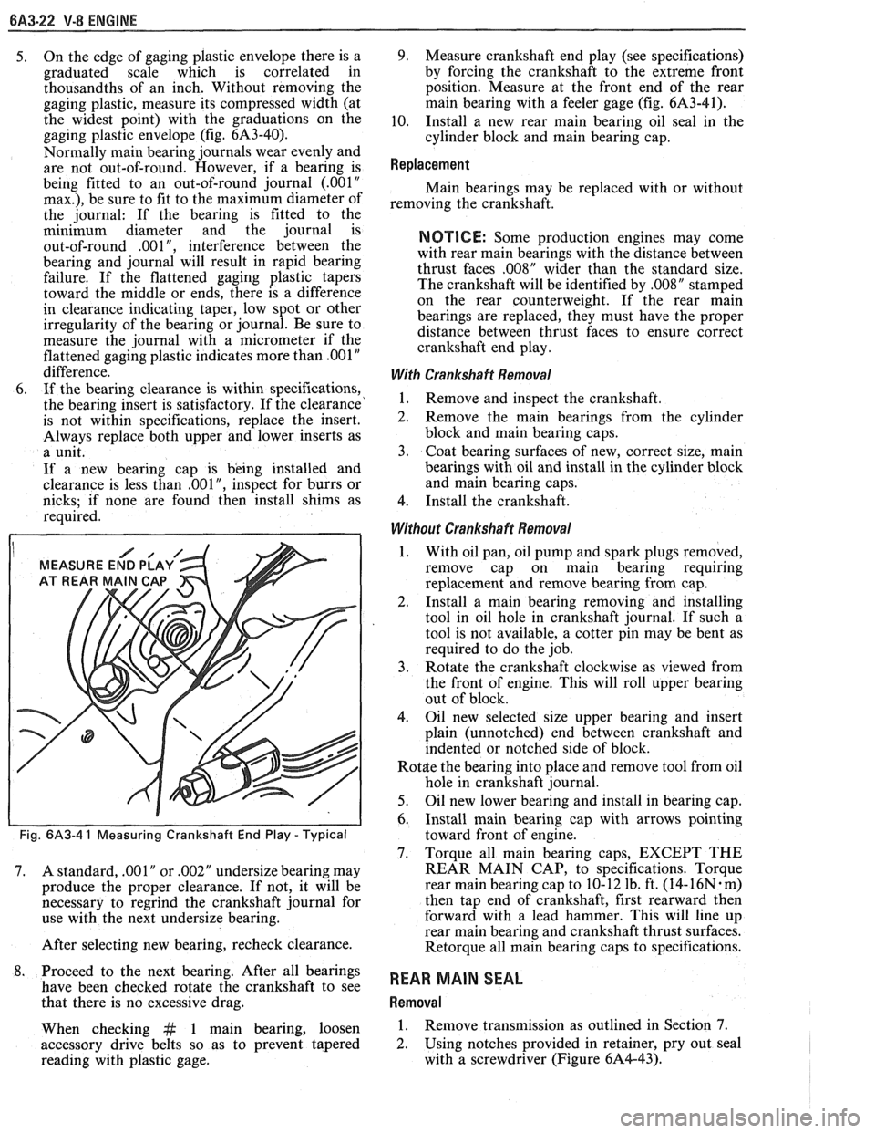
I MEASURE END PLAY
Fig. 6A3-4 1 Measuring Crankshaft End Play - Typical
7. A standard, .001" or .002" undersize bearing may
produce the proper clearance. If not, it will be
necessary to regrind the crankshaft journal for
use with the next undersize bearing.
After selecting new bearing, recheck clearance.
8. Proceed to the next bearing. After all bearings
have been checked rotate the crankshaft to see
that there is no excessive drag.
When checking
&t 1 main bearing, loosen
accessory drive belts so as to prevent tapered
reading with plastic gage.
9. Measure crankshaft end play (see specifications)
by forcing the crankshaft to the extreme front
position. Measure at the front end of the rear
main bearing with a feeler gage (fig.
61\3-41),
10. Install a new rear main bearing oil seal in the
cylinder block and main bearing cap.
Replacement
Main bearings may be replaced with or without
removing the crankshaft.
NOTICE: Some production engines may come
with rear main bearings with the distance between
thrust faces
,008" wider than the standard size.
The crankshaft will be identified by
,008" stamped
on the rear counterweight. If the rear main
bearings are replaced, they must have the proper
distance between thrust faces to ensure correct
crankshaft end play.
With Crankshaft Removal
1. Remove and inspect the crankshaft.
2. Remove the main bearings from the cylinder
block and main bearing caps.
3. Coat bearing surfaces of new, correct size, main
bearings with oil and install in the cylinder block
and main bearing caps.
4. Install the crankshaft.
Without Crankshaft Removal
1. With oil pan, oil pump and spark plugs removed,
remove cap on main bearing requiring
replacement and remove bearing from cap.
2. Install a
main bearing removing and installing
tool in oil hole in crankshaft journal. If such a
tool is not available, a cotter pin may be bent as
required to do the job.
3. Rotate the crankshaft clockwise as viewed from
the front of engine. This will roll upper bearing
out of block.
4. Oil new selected size upper bearing and insert
plain (unnotched) end between crankshaft and
indented or notched side of block.
Rot$e the bearing into place and remove tool from oil
hole in crankshaft journal.
5. Oil new lower bearing and install in bearing cap.
6. Install main bearing cap with arrows pointing
toward front of engine.
7. Torque all main bearing caps, EXCEPT THE
REAR MAIN CAP, to specifications. Torque
rear main bearing cap to 10- 12 lb. ft. (14-
16N. m)
then tap end of crankshaft, first rearward then
forward with a lead hammer. This will line up
rear main bearing and crankshaft thrust surfaces.
Retorque all main bearing caps to specifications.
REAR MAIN SEAL
Removal
1. Remove transmission as outlined in Section 7.
2. Using notches provided
in retainer, pry out seal
with a screwdriver (Figure 6A4-43).
Page 402 of 1825
V-8 ENGINE 6A3-23
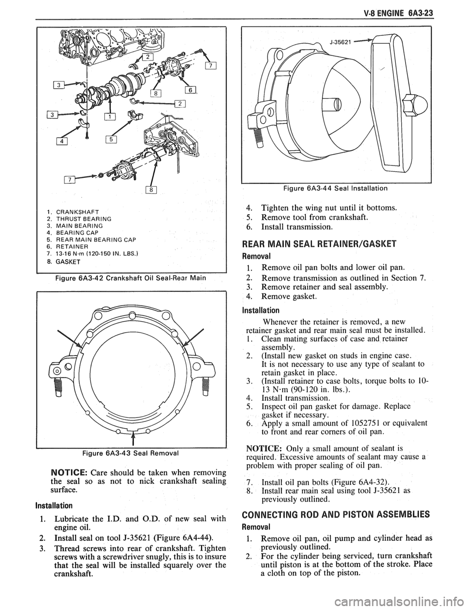
1. CRANKSHAFT 2. THRUST BEARING
3. MAlN BEARING
4. BEARING CAP 5. REAR MAlN BEARING CAP 6. RETAINER 7. 13-16 N.rn (120-150 IN. LBS.)
8. GASKET
Figure 6A3-42 Crankshaft Oil Seal-Rear Main
Figure 6/43-43 Seal Removal
NOTICE: Care should be taken when removing
the seal so as not to nick crankshaft sealing
surface.
Installation
1. Lubricate the I.D. and O.D. of new seal with
engine oil.
2. Install seal on tool J-35621 (Figure 6A4-44).
3. Thread screws into rear of crankshaft. Tighten
screws with a screwdriver snugly, this is to insure
that the seal will be installed squarely over the
crankshaft.
Figure 6A3-44 Seal Installation
4. Tighten the wing nut until it bottoms.
5. Remove tool from crankshaft.
6. Install transmission.
REAR MAlN SEAL RETAINER/GASKET
Removal
1. Remove oil pan bolts and lower oil pan.
2. Remove transmission as outlined in Section 7.
3. Remove retainer
and seal assembly.
4. Remove gasket.
lnstallation
Whenever the retainer is removed, a new
retainer gasket and rear main seal must be installed.
1. Clean mating surfaces of case and retainer
assembly.
2. (Install new gasket on studs in engine case.
It is not necessary to use any type of sealant to
retain gasket in place.
3. (Install retainer to case bolts, torque bolts
to
10-
13 N-m (90-120 in. Ibs.).
4. Install transmission.
5. Inspect oil pan gasket for damage. Replace
gasket if necessary.
6. Apply
a small amount of 105275
1 or equivalent
to front and rear corners of oil pan.
NOTICE: Only a small amount of sealant is
required. Excessive amounts of sealant may cause a
problem with proper sealing of oil pan.
7. Install oil
pan bolts (Figure
6A4-32).
8. Install rear main seal using tool 5-35621 as
previously outlined.
CONNECTING ROD AND PISTON ASSEMBLIES
Removal
1. Remove oil pan, oil pump and cylinder head as
previously outlined.
2. For
the cylinder being serviced, turn crankshaft
until piston is at the bottom of the stroke. Place
a cloth on top of the piston.
Page 406 of 1825
V-8 ENGINE 6A3-27
3. When finish honing
a cylinder bore to fit a piston,
the hone should be moved up and down at a
sufficient speed to obtain very fine uniform
surface finish marks in a cross-hatch pattern of
approximately
45" to 65" included angle. The
finish marks should be clean but not sharp, free
from imbedded particles and torn or folded
metal.
4. Permanently mark
the piston for the cylinder to
which it has been fitted and proceed to hone
cylinders and fit the remaining pistons.
NOTICE: Handle the pistons with care and do not
attempt to force them through the cylinder until
the cylinder has been honed to correct size as this
type piston can be distorted through careless
handling.
5. Thoroughly
clean the bores with hot water and
detergent. Scrub well with a stiff bristle brush and
rinse thoroughly with hot water. It is extremely
essential that a good cleaning operation be
performed. If any of the abrasive material is
allowed to remain in the cylinder bores, it will
rapidly wear the new rings and cylinder bores in
addition to the bearings lubricated by the
contaminated oil, the bores should be swabbed
and then wiped with a clean dry cloth. Cylinder
should not be cleaned with kerosene or gasoline.
Clean the remainder of the cylinder block to
remove the excess material spread during the
honing operation.
Piston Selection
1. Check USED piston to cylinder bore clearance as
follows:
a. Measure
the "Cylinder Bore Diameter"
with a telescope gage
"2-1/2" (64mm) from
top of cylinder bore").
b. Measure
the
"Piston Diameter" (at skirt
across center line of piston pin).
c. Subtract
piston diameter from cylinder bore
diameter to determine "Piston to Bore
Clearance".
d. Determine if piston to bore clearance is in
the acceptable range.
2. If
used piston is not acceptable, check Piston Size
Chart and determine if a new piston can be
selected to fit cylinder bore within the acceptable
range.
3. If
cylinder bore must be reconditioned, measure
new piston diameter (across center line of piston
pin) then hone cylinder bore to correct clearance
(preferable range).
4. Mark the piston to identify the cylinder for which
it was fitted.
OIL FILTER BYPASS VALVE
Inspection and Replacement
With the oil filter removed, check the spring and
fibre valve for operation. Inspect for a cracked or
broken valve. If replacement is necessary, the oil filter
adapter and bypass valve assembly must be replaced as an
assembly. Clean valve chamber in cylinder block
thoroughly. Torque retaining screws to specifications.
ENGINE ASSEMBLY
Removal
1. Disconnect battery.
2. Remove air cleaner.
3. Remove hood.
4. Drain radiator.
5. Remove lower radiator hose.
6. Remove upper fan shroud.
7. Remove upper radiator hose and coolant
recovery hose.
8. Remove transmission cooler lines.
9. Remove radiator.
10. Remove fan assembly.
1 1. Remove heater hoses.
12. Disconnect
carburetor linkage, includes cruise
control detent cable.
13. Remove vacuum brake booster line.
14. Remove
distributor cap and lay wiring aside.
15. Disconnect necessary wires and hoses.
16. Remove power steering
pump and lay aside.
17. Raise vehicle.
18. Remove exhaust
pipes at exhaust manifold.
19. Remove dust cover.
20. Remove converter bolts.
2 1. Disconnect starter wires.
22. Remove bell housing bolts.
23. Remove
motor mount through bolts.
24. Disconnect fuel lines
at fuel pump.
25. Lower vehicle.
26. Support transmission.
27. Remove
A.I.R./Converter pipe bracket.
28. Remove engine, include removing wire
from
bracket at rear left of engine.
Installation
1. Position engine
assembly in vehicle.
2. Attach
motor mount to engine brackets and
lower engine in place.
3. Remove engine lifting device.
4. Remove transmission floor jack.
5. Raise vehicle on hoist.
6. Install mount "through" bolts. Torque to
specifications.
7. Install bell housing bolts. Torque to
specifications.
8. On vehicles with automatic transmissions, install
I
converter to flywheel attaching bolts. Torque to
specifications.
9. Install flywheel splash shield of converter
housing cover as applicable. Torque attaching
bolts to specifications.
I
10. Install starter wires.
1 1. Connect fuel lines.
12. Connect exhaust pipe at manifold.
13. Lower vehicle on hoist.
14. Reinstall power steering pump, if so equipped.
15. Connect necessary wires and hoses.
Page 407 of 1825
6A3-28 V-8 ENGINE
16. Install
radiator and fan shroud and reconnect
radiator and heater hoses.
17. Fill cooling system.
18. Fill
crankcase with oil. See owner's manual for
specifications.
19. Install air cleaner.
20. Install hood.
21. Connect battery cables.
NOTICE: To avoid possible arcing of battery,
connect positive battery cable first.
22. Start engine, check for leaks and check timing.
CRANKSHAFT
The crankshaft can be removed while the engine
is disassembled for overhaul, as previously outlined, or
without complete disassembly.
Removal
With the engine removed from the vehicle and the
transmission and/or clutch housing removed
from the engine, mount engine in stand and
clamp securely.
Remove the oil dip stick and oil dip stick tube, (if
applicable).
Remove the starting motor, clutch assembly (if
equipped) and flywheel.
Remove the spark plugs.
Remove crankshaft pulley and torsional damper.
Remove oil pan and oil pump.
Remove crankcase front cover, and if so
equipped, remove timing chain and camshaft
sprocket.
Check the connecting rod caps for cylinder
number identification. If necessary, mark them.
Remove the connecting rod caps and push the
pistons to top of bores.
Remove main bearing caps and lift crankshaft out
of cylinder block.
Remove rear main bearing oil seal and main
bearings from cylinder block and main bearing
caps.
Cleaning and Inspection
1. Wash crankshaft in solvent and dry with
compressed air.
2. Measure dimensions of main bearing journals and
crankpins with a micrometer for out-of-round,
taper or undersize. (See Specifications.) 3.
Check crankshaft for run-out by supporting at
the front and rear main bearings journals in
"V"
blocks and check at the front and rear
intermediate journals with a dial indicator. (See
Specifications.)
4. Replace or recondition the crankshaft if out of
specifications.
SPROCKET OR GEAR REPLACEMENT
e Remove crankshaft sprocket using Tool
5-5825, install using Tool J-5590.
Installation
1.
Install rear main bearing oil seal in cylinder block
and rear main bearing cap grooves. Install with
lip of seal toward front of engine. Where seal has
two lips install lip with helix towards front of
engine.
2. Lubricate lips of seal with engine oil. Keep oil off
parting line surface.
3. Install main bearings in cylinder block and main
bearing caps then lubricate bearing surface with
engine oil.
4. Install crankshaft, being careful not to damage
bearing surfaces.
5. Recheck bearing clearances using plastigage.
6. Apply a thin coat of brush-on type oil sealing
compound to block mating surface and
corresponding surface of cap only. Do not allow
sealant on crankshaft or seal.
7. Install main bearing caps with arrows pointing
toward front of engine.
8. Torque all except rear main bearing cap bolts to
specifications. Torque rear main bearing cap bolts
to 10-12 lbs. ft. (14-16
N.m)then tap end of
crankshaft, first rearward then forward with a
lead hammer. This will line up rear main bearing
and crankshaft thrust surfaces.
Retorque all main
bearing cap bolts to specifications.
9. Measure crankshaft end play with a feeler gage.
Force crankshaft forward and measure clearance
between the front of the rear main bearing and the
crankshaft thrust surface.
10. Install flywheel and torque to specifications. A
wood block placed between the crankshaft and
cylinder block will prevent crankshaft from
rotating.
Align dowel hole in flywheel with dowel
hole in crankshaft. On vehicles equipped
with automatic transmissions, install
flywheel with the converter attaching pads
towards transmission.
GENERAL DATA
TYPE .................................................................................................................................. 90" V-8
DISPLACEMENT
............................................................................... 305 Cu. In., 350 Cu. In.
......................................................... LITER (VIN) ................................... ...... 5.0, (E), (F), 5.7 (8)
RPO ......................................................................................................................... L03, LB9, L98
BORE ........................................................................................................................ 3.736, 4.000
STROKE
........................... .. ....................................................................................... 3.480, 3.480
COMPRESSION RATIO
................................................................................... 931, 931, 9.5:1
FIRING ORDER .................................................................................................... 1-8-4-3-6-5-7-2
Page 412 of 1825
ENGINE COOLING 6B-1
SECTION 6B
NE COOL
General Description ................................ 6B- 1 Off-Vehicle Leak Testing ............................... 6B-9
Radiator
...................................................... 6B- 1 Repairable Leaks ........................ ... .......... 6B- 10
Radiator Cap
......................... .. ............... 6B- 1 Repair Methods ................................................ 6B- 10
Recovery Bottle ......................................... 6B-2 Cooling Fin Removal ................................ 6B- 10 - ............................................. Fans ............................................................... 6B-2 Tube Blocking 6B- 1 1 ............ Header Repair ....................... .... 6B- 1 1 Temperature Switch ..................................... 6B-2 General Core Repair 6B- 1 1 ....................................
........................... Coolant Temperature Fan Switch ................ 6B-2 Tank
Gasket ~eik Repair 6B- 12
................... Thermostat .. 6B-3 Oil
Cooler Gasket Replacement
6B- 13 ............... ................................
...........................................................
Coolant Recovery System 6B-3 Recore 6B- 14 ............................. Special Tools ..................................................... 6B- 14 Diagnosis ..................................................... 6B-3
.............................. ..................................... Service Procedures 6B-3 On-Vehicle Service 6B-14
Cooling System Care
............................... 6B-3 Thermostat ....................................... 6B-14
Draining and Refilling the Cooling Electric Cooling Fan ............................. 6B-15
System
................................................... 6B-7 Water Pump .................... .... ......... 6B-15
Drive Belt
...................... .. .......................... 6B-7 Coolant Recovery Bottle ........................ 6B-16
.......................................... Aluminum Radiator Service .................... 6B-8 Radiator 6B-17
Diagnosis .................................................... 6B-8
Leak Testing
.............................................. 6B-8
On-Vehicle Pressure Testing
...................... .... 6B-9
GENERAL DESCRIPnIBN
The cooling system maintains engine temperature
5" below the filler neck which reads, "Important - for
at an efficient level during all engine operating repair see Harrison Service Manual". Service
conditions. When the engine is cold the system cools procedures for the aluminum plastic radiator are
slowly, or not at all, to allow the engine to warm up described in that manual and in this section.
quickly.
The cooling system includes a radiator and
Radiator Cap
recovery sub-system, cooling fan, thermostat and
housing, water pump, and drive belts.
Operation of the cooling system requires proper
functioning of all components. Coolant is drawn from
the radiator by the water pump and circulated through
water jackets in the engine block, intake manifold, and
cylinder
head(s), and then directed back to the radiator
where it's cooled.
This system directs some coolant through hoses
to the heater core, to provide for heating and
defrosting. A recovery bottle is connected to the
radiator to recover coolant displaced by expansion
from high temperatures and maintain correct coolant
level. As the coolant cools and contracts it is drawn
back into the radiator by vacuum.
RADIATOR
A cross-flow radiator is used on all models. Tanks
in this type radiator are located to the right and left of
the core, instead of above and below.
Radiators used with automatic transmissions
have oil coolers with inlet and outlet fittings for
transmission fluid circulation. Cars with manual
transmissions use radiators without oil coolers.
Vehicles equipped with air conditioning use a radiator
with extra cooling capability.
An aluminum-plastic radiator, used on some
models, can be identified by a note on the outlet tank A pressure-vent
cap is used on the cross-flow
radiator to allow a buildup of
103 kPa (15 psi) in the
cooling system. This pressure raises the boiling point
of coolant to approximately 125°C (262°F) at sea level.
Do not remove radiator cap to check engine
coolant level; check coolant visually at the
see-through coolant reservoir. Coolant should
be added only
to the reservoir.
CAUTION: As long as there
is
pressure in the cooling system, the
temperature can be considerably
higher than the boiling temperature
of
the solution in the radiator without
causing the solution to boil. Removal
of the radiator cap while engine is hot
and pressure is high will cause
the
solution to boil instantaneously and
possibly with explosive
force, spewing
the solution over engine, fenders and
person removing cap. If the solution
contains flammable antifreeze, such
as alcohol (not recommended for use
at any time), there is also the
possibility
of causing a serious fire.
The pressure-type radiator filler cap contains a
blow off or pressure valve and a vacuum or
atmospheric valve (Figure
1). The pressure valve is
held against its seat by a spring of pre-determined