1988 PONTIAC FIERO transmission
[x] Cancel search: transmissionPage 418 of 1825
ENGINE COOLING BB-7
NOTICE: If recommended quality antifreeze is
used, supplemental inhibitors or additives claiming
to provide increased cooling capability are not
necessary. They may be detrimental to the efficient
operation of the system, and represent an
unnecessary operating expense.
Every 12 months or 15,000 miles, the cooling
system should be serviced as follows;
1. Wash radiator cap and filler neck with clean
water.
2. Check coolant for proper level and freeze
protection.
3. Pressure test system and radiator cap for proper
pressure holding capacity, 103
kPa (15 psi). If
replacement of cap is required, use the proper cap
specified for car model.
4. Tighten hose clamps and inspect all hoses. Replace
hoses whenever cracked, swollen or otherwise
deteriorated.
5. Clean frontal area of radiator core and air
conditioning condenser.
DRAINING AND REFILLING THE COOLING
SYSTEM
Replace hoses every 24 months or 30,000 miles or
earlier if cracked, swollen or otherwise deteriorated.
Every two years or 30,000 miles, whichever first
occurs, the cooling system should be flushed and
refilled using the following recommended procedure:
1. Remove radiator cap, or thermostat housing cap
(VIN
0, J, R and U), when engine is cool by:
a. Slowly
rotating cap counterclockwise to
detent. (Do not press down while rotating.)
b. Wait until any
residual pressure (indicated
by a hissing sound) is relieved.
c. After all hissing ceases, press down on cap
while continuing to rotate
counterclockwise.
CAUTION: To avoid the danger of
being burned, do not remove radiator
cap while engine and radiator are still
hot. Scalding fluid and steam may be
blown out under pressure.
2. Remove the thermostat by using the wire handle
to lift it out of the housing (VIN
0, J, R and U).
3. With the thermostat removed, reinstall the
thermostat housing cap (VIN
0, J, R and U).
4. Open radiator drain valve and block drain plugs
to drain coolant. On VIN R and
9 (P series)
engines, open coolant pipe plugs.
5. Close valve. Reinstall drain plugs, and add
sufficient water to fill system.
6. Run engine, drain and refill the system, as
described in steps
4 and 5 a sufficient number of
times, until the drained liquid is nearly colorless.
Important
BLOCK DRIVE WHEELS, place
transmission in PARK (automatic
transmission) or NEUTRAL (manual
transmission) and set the parking brake. 7.
Allow system to drain completely. Then close
radiator drain valve tightly, and reinstall block
drain plugs.
8. Remove recovery cap leaving hoses in place.
Remove coolant recovery tank and empty of
fluid. Flush tank with clean water, drain and
reinstall.
9. Add sufficient ethylene glycol coolant, meeting
GM specification 1825-M, to provide the
required freezing and corrosion protection
- at
least 50 percent solution -37°C (-34°F). Fill
radiator to the base of the radiator fill neck and
add sufficient coolant to the recovery tank to
raise level to the "FULL" mark. Reinstall
recovery tank cap.
10. Run engine, with radiator cap or thermostat
housing cap removed, until normal operating
temperature is reached. (Radiator upper hose
becomes hot.)
11. With engine idling, add coolant until level
reaches bottom of filler neck and reinstall cap,
making certain arrows line up with overflow tube.
CAUTION: Under some conditions, the
ethylene glycol in engine coolant is
flammable. To help avoid being
burned when adding coolant, DO NOT
spill
it on the exhaust system or hat
engine parts.
It is the owner's responsibility to keep the freeze
protection at a level appropriate to the
temperatures which may occur in the area of
vehicle operation.
a. Maintain
cooling system freeze protection
at
-37°C (-34"F), to ensure protection
against corrosion and loss of coolant from
boiling, even though freezing temperatures
are not expected.
b. Add ethylene glycol base coolant that meets
GM Specification 1825-M, when coolant
additions are required because of coolant
loss, or to provide additional protection
against
freezing at temperatures lower than
-37°C (-34°F).
NOTICE: Alcohol or methanol base coolants, or
plain water, are not recommended at any time.
DRlVE BELT
NOTICE: Routine inspection of the belt may
reveal cracks in the belt ribs. These cracks will
not impair belt performance and therefore should
not be considered a problem requiring belt
replacement. However, the belt should be
replaced if belt slip occurs or if sections of the
belt ribs are missing.
A single (serpentine) belt is used to drive all
engine accessories formerly driven by multiple drive
belts. All belt driven accessories are ridgedly mounted
with belt tension maintained by a spring loaded
tensioner.
The drive belt tensioner has the ability to control
belt tension over a fairly broad range of belt lengths.
Page 419 of 1825
68-8 ENGINE COOLING
However, there are limits to the tensioner's ability to
The tensioner has rovisions for a visual check to
compensate for varying lengths of belts. With the
ten- verify that it is in t e "operating range" (see Figures
sioner outside of its operating range, poor tension
608 and 609). R
control andlor damage to the tensioner may result.
ALUMINUM RADIATOR REPAIR
This radiator utilizes an aluminum core with
plastic side tanks. The core and side tanks can be
replaced separately and core repair is easily made with
the hot melt adhesive method. A transaxle oil cooler
is located in one of the side tanks. The oil cooler can
be replaced. The drain cock is located on the lower part
of one of the tanks. The drain cock is also serviceable.
Core
The core is made of aluminum and is of the
crossflow design. It utilizes large tubes that resist
plugging, and repairs to the tubes and core are easily
made using the hot melt adhesive method.
The core is attached to the tanks by clinched tabs
on the core that can be bent back if tank or core
replacement is required.
If the damage to a tube is too severe, a tube can
be blocked or plugged as explained in "Tube Blocking.
" No more than two tubes should ever be blocked on
a core. Also replace the core if more than three tabs are
broken on one side, or if two adjacent tabs are broken.
Tanks
The tanks are attached to the core by the use of
clinched tabs. The clinched tabs can be bent back if the
tanks need to be removed from the core. Bend the tabs
back only enough to remove the tank. Overbending
will weaken the tabs.
A high temperature rubber gasket is used to seal
the mating surface between the core and the tank. (See
Fig. 8). The gasket must be replaced any time a tank
is removed from the core.
Transaxle Oil Cooler
The transaxle oil cooler is located in one of the
radiator side tanks. The oil cooler can be replaced by
removing the tank from the core.
A leaking oil cooler gasket can be replaced
without removing the tank from the core.
Drain Cock
The aluminum/plastic radiator utilizes a two
piece plastic drain cock and a rubber seal. The drain
cock is serviceable (See Fig.
9).
ALUMINUM RADIATOR SERVICE
The aluminum-plastic radiator can be repaired at
the dealership. The following components are easily
replaced:
e Core
e Tanks and gaskets
o Oil coolers and gaskets
e Drain cock and gasket The
tanks cannot be repaired if broken or
cracked. The radiator core can be replaced and the new
core used with the original tanks and oil cooler.
Precautions
As with all cooling system service, take measures
to prevent personal injury and damage to the system.
CAUTION: To help avoid the danger of
being burned, do not remove the
radiator cap while the engine and
radiator are
still hot. Scalding fluid
and steam can be blown out under
pressure if the
cap is taken off too
soon.
NOTICE: DO NOT USE "BOIL OUT" TANKS
OR VATS. Common service methods may
actually destroy an aluminum radiator. Caustic or
lye cleaning solutions must NOT be used for
aluminum radiators.
e Do not open the hood if you can see, or hear,
steam or coolant escaping from the engine
compartment.
e Do not remove radiator cap if radiator feels
warm.
e Do not remove the radiator cap or coolant
recovery tank cap if the coolant in the recovery
tank looks like it is boiling.
Wear eye protection.
e Wear gloves to protect your hands against
excessive heat, or the effects of chemicals on your
skin.
o Prevent dirt and water from entering the
transmission oil cooler.
e Do not use boil-out tanks, or vats, or other tanks
that have been used for copper and brass
radiators. The flux, acid, and caustic cleaners
remaining in these tanks will attack the
aluminum and cause radiator failure.
A separate
test tank containing clean water is strongly
recommended for servicing aluminum-plastic
radiators.
RIOTICE: Never use shop air that is not regulated
at
20 psi (138 kPa) to pressure test radiator.
Pressures over
20 psi (138 kPa) will damage the
radiator.
DIAGNOSIS
Leak Testing
Some core leaks can be detected by merely adding
water to the radiator. It is helpful to clean the core so
that the damaged area can be more easily found.
Page 428 of 1825
ENGINE COOLING 68.17
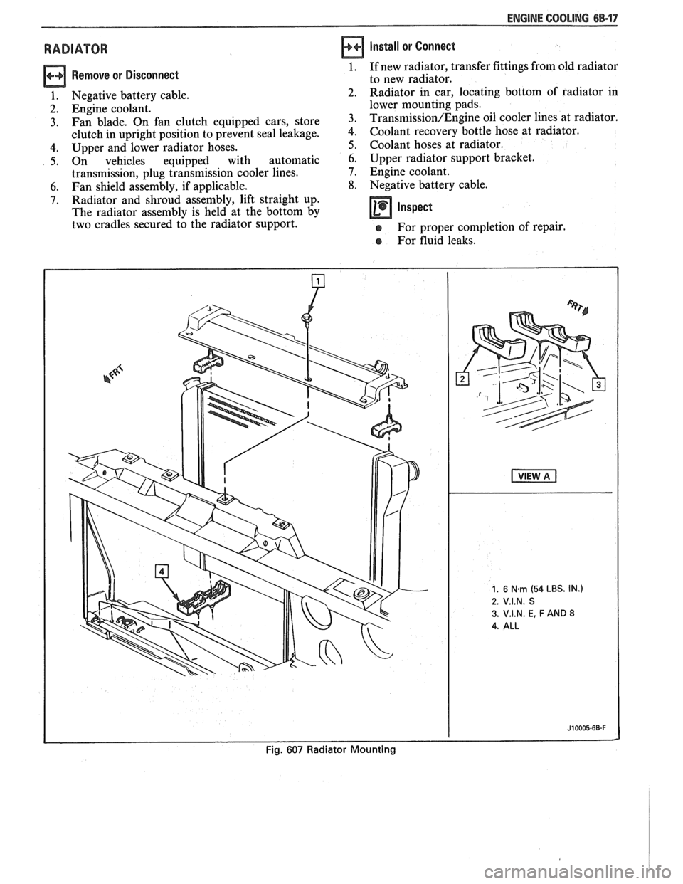
RADIATOR
Remove or Disconnect
1. Negative battery cable.
2. Engine coolant.
3. Fan blade. On fan clutch equipped cars, store
clutch in upright position to prevent seal leakage.
4. Upper and lower radiator hoses.
5. On vehicles equipped with automatic
transmission, plug transmission cooler lines.
6. Fan shield assembly, if applicable.
7. Radiator and shroud assembly, lift straight up.
The radiator assembly is held at the bottom by
two cradles secured to the radiator support.
Install or Connect
1. If new radiator, transfer fittings from old radiator
to new radiator.
Radiator in car, locating bottom of radiator in
lower mounting pads.
Transmission/Engine oil cooler lines at radiator.
Coolant recovery bottle hose at radiator.
Coolant hoses at radiator.
6. Upper radiator support bracket.
7. Engine coolant.
8. Negative battery cable.
Inspect -
e For proper completion of repair.
e For fluid leaks.
Page 430 of 1825
ENGINE COOLING 6B-19
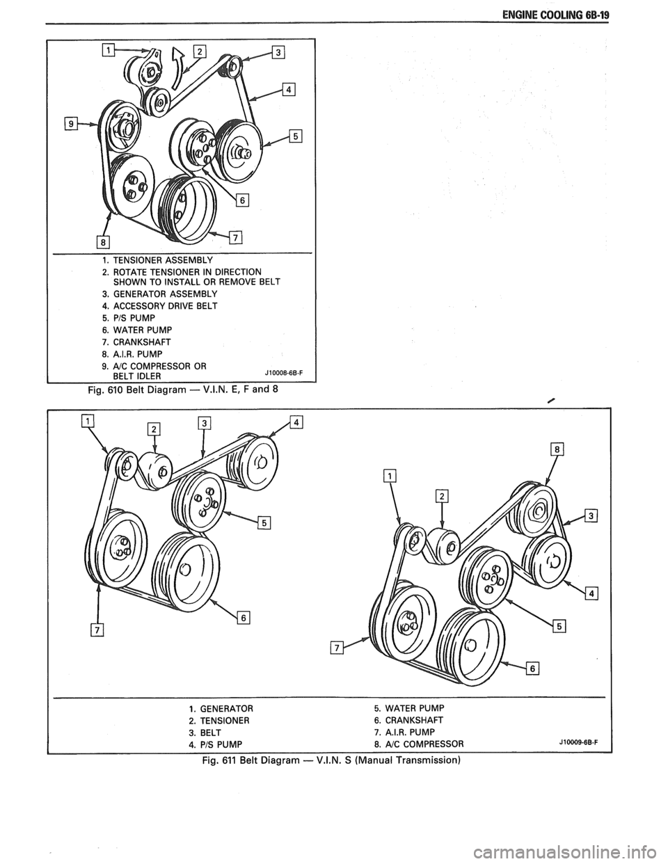
1. TENSIONER ASSEMBLY
2. ROTATE TENSIONER IN DIRECTION
SHOWN TO INSTALL OR REMOVE BELT
3. GENERATOR ASSEMBLY
4. ACCESSORY DRIVE BELT
5. PIS PUMP
6. WATER PUMP
7. CRANKSHAFT
8. A.I.R. PUMP
Fig. 610 Belt Diagram - V.I.N. E, F and 8
1. GENERATOR 5. WATER PUMP
2. TENSIONER 6. CRANKSHAFT
3. BELT 7. A.I.R. PUMP
4. PIS PUMP 8. AIC COMPRESSOR J10009-68-F
Fig. 611 Belt Diagram -- V.I.N. S (Manual Transmission)
Page 431 of 1825
6B-20 ENGINE COOLING
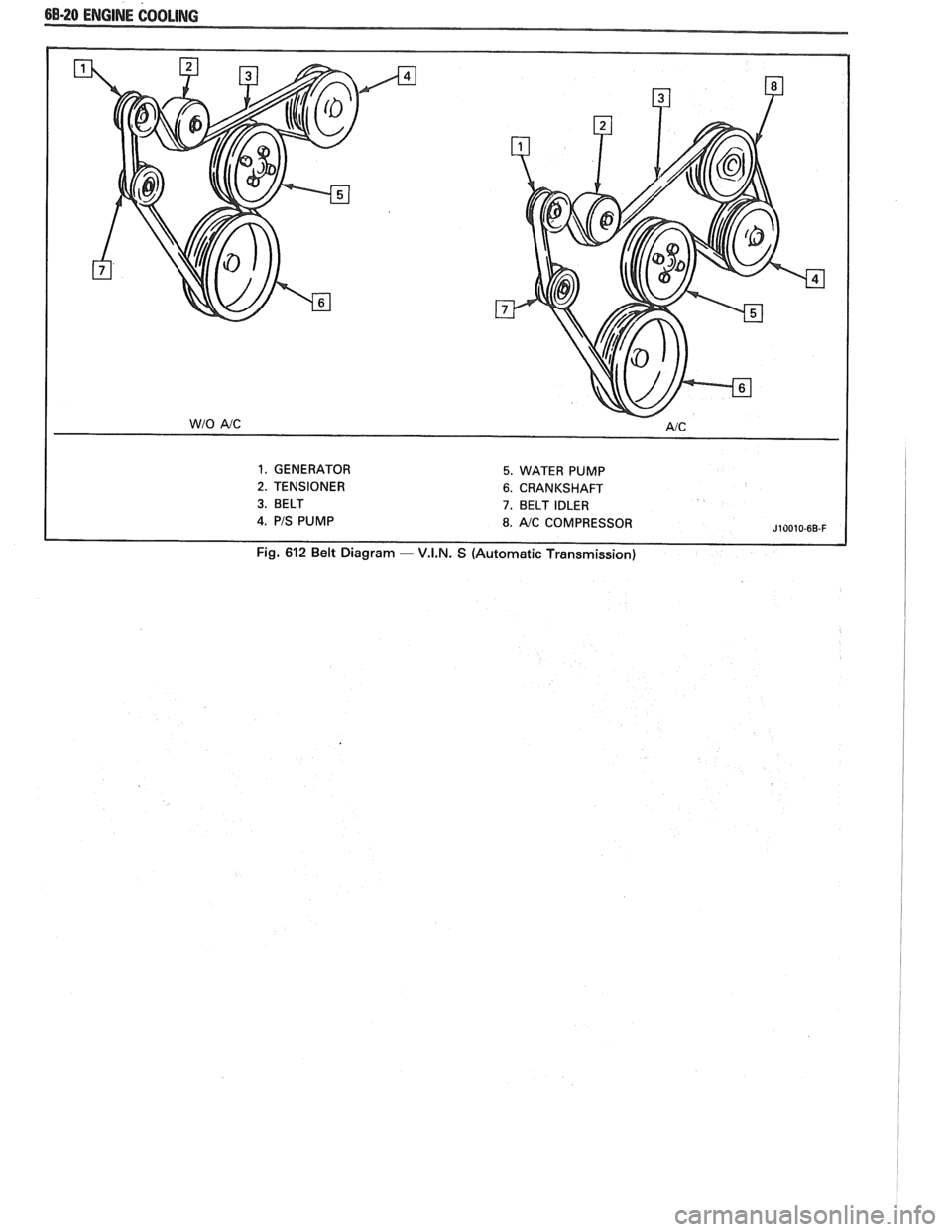
1. GENERATOR 5. WATER PUMP
2. TENSIONER 6. CRANKSHAFT
3. BELT 7. BELT IDLER
J10010-6B-F
Fig. 612 Belt Diagram - V.I.N. S (Automatic Transmission)
Page 447 of 1825
6D1-4 BATTERY
VOLTAGE
A. 16.0 or more
B. 14.0
- 15.9
C. 13.9 or less HOURS
1. Set parking brake and place automatic
Up to 4 Hours transmission in "PARK" (NEUTRAL for
Up to 8 Hours manual transmission.) Turn off the ignition,
Up to 16 Hours turn off lights, and all other electrical
If the charge current is still not
measurable
at the end of the above charging
times, the battery should be replaced.
If the charge current is measurable during
the charging time, the battery is considered to be
good and charging should be completed in the
normal manner.
5. It
is important to remember that a completely
discharged battery must be recharged for a
sufficient number of ampere hours (AH) to
restore it to a usable state. As a general rule of
thumb, using the reserve capacity rating (RC) of
the battery as the number of ampere hours of
charge will usually bring the green dot into view.
For example, if battery is rated at 75 RC minutes,
it would be completely recharged as follows:
10 ampere charge x 7-1/2 hours
= 75 AH
25 ampere charge x 3 hours = 75 AH, etc.
6. It
is recommended that any battery recharged by
this procedure be
LOAD TESTED to establish
serviceability.
JUMP STARTING IN CASE OF EMERGENCY
WITH AUXILIARY (BOOSTER) BAVEEWY
NOTICE: Do not push or tow the vehicle to start.
Damage to the emission system, or to other parts
of the vehicle may result.
Both booster and discharged battery should be
treated carefully when using jumper cables. Follow the
procedure outlined below, being careful not to cause
sparks:
CAUTION: Departure from these
conditions or the procedure below
could result in:
(1) Serious personal
injury (particularly to eyes) or property
damage from such causes as battery
explosion, battery acid, or electrical
burns; and/or
(2) damage to electronic
components of either vehicle.
Never expose battery to open flame or electric
spark
- batteries generate a gas which is flammable and
explosive.
Remove rings, watches, and other jewelry. Wear
approved eye protection.
Do not allow battery fluid to contact eyes, skin,
fabrics, or painted surfaces
- fluid is a corrosive acid.
Flush any contacted area with water immediately and
thoroughly. Be careful that metal tools or jumper
cables do not contact the positive battery terminal (or
metal in contact with it) and any other metal on the
car, because a short circuit could occur. Batteries
should always be kept out of the reach of children.
loads.
2. Check the built-in hydrometer. If it is clear or
light yellow, replace the battery.
3. Attach the end of one jumper cable to the positive
terminal of the booster battery and the other end
of the same cable to the positive terminal of the
discharged battery. Do not permit vehicles to
touch each other as this could cause a ground
connection and counteract the benefits of this
procedure. (Use 12-volt battery only to jump start
the engine).
4. Attach one end of the remaining negative cable
to the negative terminal of the booster battery,
and the other end to a solid engine ground (such
as
A/C compresser bracket or generator
mounting bracket) at least 18 inches from the
battery of the vehicle being started (DO NOT
CONNECT DIRECTLY TO THE NEGATIVE
TERMINAL OF THE DEAD BATTERY).
5. Start the engine of the vehicle that is providing
the jump start and turn off electrical accessories.
Then start the engine in the car with the
discharged battery.
6. Reverse these directions exactly when removing
the jumper cables. The negative cable must be
disconnected from the engine that was jump
started first.
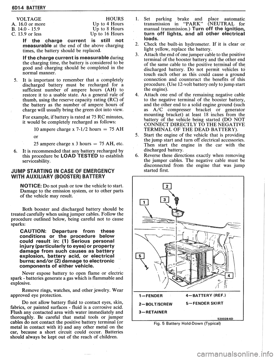
I-FENDER 4-BATTERY (REF.)
2- BOLTISCREW 5-FENDER SKIRT
3-RETAINER
520028-60
Fig. 5 Battery Hold-Down (Typical)
Page 487 of 1825
6E2-2 5.OL (VIN El DRlVEABlLlTV AND EMISSIONS
Power Steering Pressure Switch (PSPS) Diagnosis
Chart C-1
E ......................... C1-18
ldle Air Control (IAC) Valve Check
Chart C-2C
......................... C2-16
Canister Purge Valve Check
Chart C-3
.......................... C3-4
Ignition System Check
Chart C-4
......................... C4-4
Electronic Spark Control (ESC) System Check
Chart C-5
.......................... C5-4
A.I.R. Management Check . Pedes Valve
Chart C-6
......................... C6-6
Exhaust Gas Recirculation (EGR) Check
Chart C-7
.......................... C7-4
Transmission Converter Clutch (TCC)
Electrical Diagnosis Chart C-8A
(1 of 2) ... C8-4
700-4R Transmission . Electrical Diagnosis
Chart C8-A
(2 of 2) ................... C8-6
Manual Transmission Shift Light Diagnosis
Chart
C-8B ........................ C8-8
SECTION C . COMPONENT SYSTEMS
Table of Contents .................... C-1
SECTION
C1
ELECTRONIC CONTROL MODULE AND SENSORS
GENERAL DESCRIPTION
............... C1-1
ELECTRONIC CONTROL MODULE (ECM) . . C1-1
PROM ........................... C1-1
CALPAK .......................... C1-2
ECMFUNCTION .................... C1-2
INFORMATION SENSORS ............. C1-2
Engine Coolant Temperature Sensor . . C1-2
MAP Sensor ...................... C1-2
MAT Sensor ...................... C1-3
Oxygen (Oz) Sensor ................ C1-3
Throttle Position Sensor (TPS) ........ C1-3
Knock Sensor .................... C1-4
Park Neutral Switch (Auto Only) ...... C1-4
Crank Signal ..................... C1-4
A/C Request Signal ............... C1-4
Vehicle Speed Sensor (VSS) ......... C1-4
Distributor Reference Signal ......... C1-4
(PSPS) ......................... C1-4
DIAGNOSIS ......................... C1-5
ECM ............................. C1-5
PROM ........................... C1-5
ECMINPUTS ....................... C1-5
Coolant Temperature Sensor ........ C1-5
MAT Sensor ...................... C1-5
MAP Sensor ...................... C1-6
Oxygen (Oz) Sensor ................ C1-6
Throttle Position Sensor (TPS) ........ C1-6
Vehicle Speed Sensor (VSS) ......... C1-6
P/N Switch ....................... C1-6
(PSPS) ......................... C1-6
A/C Request Signal ................ C1-6
......... Distributor Reference Signal C1-6
Knock Signal ................... C1-6
..................... ON-CARSERVICE C1-6
....... ELECTRONIC CONTROL MODULE C1-6
........................... PROM C1-7
Functional Check ................. C1-8
.......................... CALPAK C1-8
.................. COOLANTSENSOR C1-9
MAPSENSOR e..................... C1-9
OXYGEN (02) SENSOR ............... C1-9
THROTTLE POSITION SENSOR (TPS) ..... C1-10
PARKINEUTRAL SWITCH .............. C1-10
PARTS INFORMATION ................. C1-10
ParklNeutral Switch Diagnosis
Chart
C-1A ..................... C1-12
Crank Signal
Chart
C-1B ..................... C1-14
MAP Output check
Chart C-1 D
..................... C1-16
Power Steering Pressure Switch (PSPS) Diagnosis
ChartC-lE ..................... C1-18
SECTION C2
FUEL CONTROL SYSTEM
GENERAL DESCRIPTION
............... C2-1
PURPOSE ...*..................... C2-1
MODES OF OPERATION .............. C2-1
Starting Mode ................... C2-1
Clear Flood Mode ................ C2-2
RunMode ...................... C2-2
Open Loop ...................... C2-2
Closed Loop ..................... C2-2
Acceleration Mode ............... C2-2
Deceleration Mode ............... C2-2
Battery Correction Mode ........... C2-2
Fuel Cut Off Mode ................ C2-2
... FUEL CONTROL SYSTEM COMPONENTS C2-2
BASIC SYSTEM OPERATION ........... C2-3
THROTTLE BODY INJECTION (TBI) UNIT ... C2-3
Fuel Injectors .................... C2-3
Pressure Regulator ............... C2-3
.......... Idle Air Control (IAC) Valve C2-4
........ Throttle Position Sensor (TPS) C2-4
FUELPUMP ........................ C2-5
....... FUEL PUMP ELECTRICAL CIRCUIT C2-5
DIAGNOSIS
......................... C2-5
FUEL CONTROL .................... C2-5
......... Idle Air Control Valve (IAC) C2-5
Dr~veability ..................... C2-5
ON VEHICLE SERVICE
................. C2-5
...... GENERALSERVICE INFORMATION C2-5
Fuel Pressure Relief ............... C2-7
........... Fuel System Pressure Test C2-7
Cleaning and lnspect~on ........... C2-7
......... Thread Lockrng Compound C2-7
Page 488 of 1825
DRIVEABILITY AND EMISSIONS 5.OL (VIN E) 6E2-3
........ FUEL METER COVER ASSEMBLY C2-7
FUEL INJECTOR ASSEMBLIES .......... C2-8
FUEL METER BODY ASSEMBLY ......... C2-9
..... THROTTLE POSITION SENSOR (TPS) C2-10
IDLE AIR CONTROL (IAC) VALVE ........ 62-1 1
THROTTLE BODY ASSEMBLY
.......... C2-11
MINIMUM IDLE SPEED CHECK .......... C2-12
... THROTTLE BODY INJECTION (TBI) UNIT C2-13
FUEL
HOSEIPIPE ASSEMBLIES .......... C2-13
Materials ...................... C2-13
Fuel Line Repair .................. C2-13
FUEL PUMP RELAY .................. C2-13
............... OILPRESSURESWITCH C2-13
PARTS INFORMATION ................. C2-14
Idle Air Control (IAC) Valve Check
Chart C-2C
..................... C2-16
SECTION C3
EVAPORATIVE EMISSION CONTROL SYSTEM
GENERAL DESCRIPTION
............... C3-1
........................ PURPOSE C3-1
VAPOR CANISTER
................... C3-1
EVAPORATIVE EMISSION SYSTEM
....... C3-1
IN-TANK PRESSURE CONTROL VALVE
. . C3-2
.... RESULTS OF INCORRECT OPERATION C3-2
........................ DIAGNOSIS C3-2
VISUAL CHECK OF CANISTER
.......... C3-2
CANISTER PURGE SOLENOID
.......... C3-2
ON-CAR SERVICE ................. C3-2
FUEL VAPOR CANISTER
R/R ............ C3-2
CANISTER HOSES
.................... C3-2
PARTS INFORMATION ................ C3-2
Canister Purge Valve Check
Chart C-3
...................... C3-4
SECTION
C4
IGNITION SYSTEM I EST
GENERAL DESCRIPTION
............... C4-1
PURPOSE ........................ C4-1
OPERATION ...................... C4-1
.. DIAGNOSIS ................... ... C4-1
RESULTS OF INCORRECT EST OPER ...... C4-1
HOW CODE 42 IS DETERMINED ....... C4-2
CODE12 ........................ C4-2
CHECKING EST PERFORMANCE ........ C4-2
ON-CAR SERVICE .................... C4-2
SETTINGTIMING .................. C4-2
PARTS INFORMATION ................ C4-2
Ignition System Check
Chart C-4
................... .. . C4-4
SECTION C5
ELECTRONIC SPARK CONTROL (ESC) SYSTEM
GENERAL DESCRIPTION
................ C5-1
PURPOSE ..*...................... C5-1
OPERATION
....................... C5-1
DIAGNOSIS
......................... C5-1
RESULTS OF INCORRECT ESC OPERATION
. C5-1
ON-CAR SERVICE
..................... C5-1 ESC
KNOCK SENSOR
................ C5-1
ESCMODULE
...................... C5-1
PARTS INFORMATION ................. C5-2
Electronic Spark Control (ESC) System Check
Chart C-5
...................... C5-4
SECTION C6
AIR INJECTION REACTION (A.I.R.) SYSTEM
GENERAL DESCRIPTION
............... C6-1
PURPOSE
.*....................... C6-1
OPERATION
...................... C6-1
AIR CONTROL PEDES VALVE .......... C6-1
RESULTS OF INCORRECT OPERATION
.... C6-2
DIAGNOSIS
........................ C6-2
OPERATIONAL CHECKS
.....*........ C6-2
AirPump ...................... C6-2
Hoses and Pipes
................. C6-3
Check Valve
.................... C6-3
ON-CAR SERVICE
.................... C6-3
DRIVEBELT ...................... C6-3
AIR INJECTION PUMP
............... C6-3
AIR INJECTION CONTROL
(PEDES) VALVE
.................. C6-3
AIR INJECTION CHECK VALVE ......... C6-4
PARTS INFORMATION
................ C6-4
AIR Management Check
. Pedes Valve
Chart C-6
..................... C6-6
SECTION C7
EXHAUST GAS RECIRCULATION (EGR) SYSTEM
GENERAL DESCRIPTION
............... C7-1
PURPOSE
........................ C7-1
OPERATION
...................... C7-1
EGRCONTROL
..................... C7-1
NEGATIVE BACKPRESSURE VALVE
...... C7-1
EGR VALVE IDENTIFICATION
.......... C7-2
RESULTS OF INCORRECT OPERATION
.... C7-2
DIAGNOSIS
......................... C7-2
ON-CAR SERVICE
..................... C7-2
EGRVALVE
....................... C7-2
EGR Manifold Passage
............. C7-2
EGR CONTROL SOLENOID
............. C7-3
PARTS INFORMATION
................. C7-3
Exhaust Gas Recirculation (EGR) Check
Chart C-7
...................... C7-4
SECTION
C8
TRANSMISSION CONVERTER CLUTCH
GENERAL DESCRIPTION
............... C8-1
PURPOSE
........................ C8-1
OPERATION
...................... C8-1
CIRCUIT DESCRIPTION
............... C8-1
RESULTS OF INCORRECT TCC
OPERATION
..................... C8-2
DIAGNOSIS
......................... C8-2
ON-CAR SERVICE .................... C8-2
PARTS INFORMATION ................. C8-2