1988 PONTIAC FIERO transmission
[x] Cancel search: transmissionPage 489 of 1825
6E2-4 5.OL (VIN E) DRIVEABILITY AND EMISSIONS
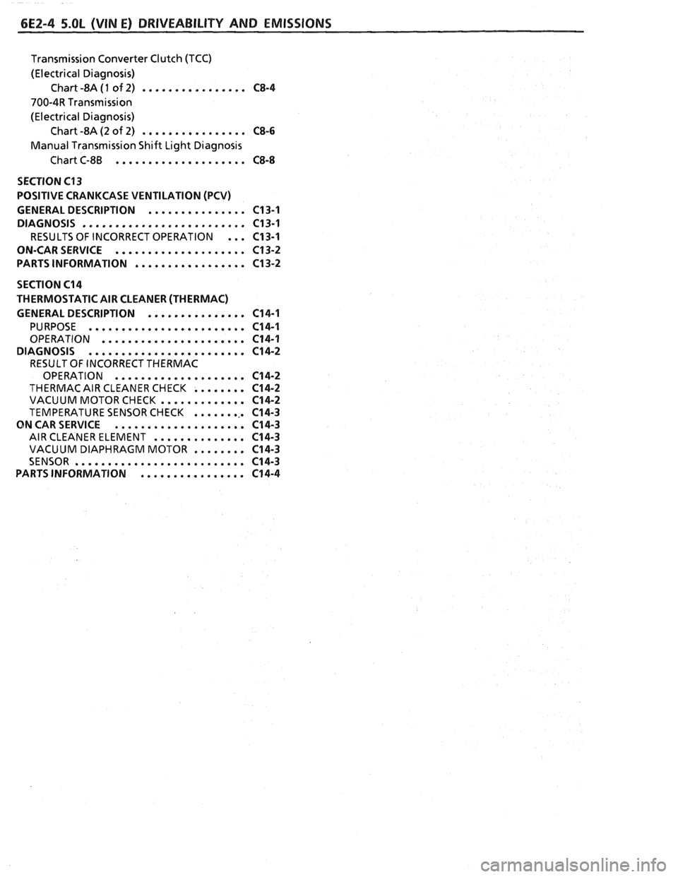
Transmission Converter Clutch (TCC)
(Electrical Diagnosis) Chart -8A
(1 of 2) ................ C8-4
700-4R Transmission
(Electrical Diagnosis) Chart -8A (2 of 2)
................ CS-6
Manual Transmission Shift Light Diagnosis
Chart C-8B
.................... CS-8
SECTION C13
POSITIVE CRANKCASE VENTILATION (PCV)
GENERAL DESCRIPTION
............... C13-1
DIAGNOSIS
......................... C13-1
RESULTS OF INCORRECT OPERATION ... C13-1
ON-CARSERVICE
.................... C13-2
PARTS INFORMATION
................. C13-2
SECTION C14
THERMOSTATIC AIR CLEANER (THERMAC)
GENERAL DESCRIPTION
............... 614-1
PURPOSE ........................ C14-1
OPERATION ...................... C14-1
DIAGNOSIS
........................ C14-2
RESULT OF INCORRECT THERMAC
OPERATION
.................... C14-2
THERMAC AIR CLEANER CHECK ........ C14-2
VACUUM MOTORCHECK ............. C14-2
TEMPERATURE SENSOR CHECK ......... C14-3
ON CAR SERVICE .................... C14-3
AIR CLEANER ELEMENT .............. C14-3
VACUUM DIAPHRAGM MOTOR ........ C14-3
SENSOR .......................... C14-3
PARTSINFORMATION ................ C14-4
Page 550 of 1825
DRIVEABILITY AND EMISSIONS 5.OL (VIN E) 6E2-B-3
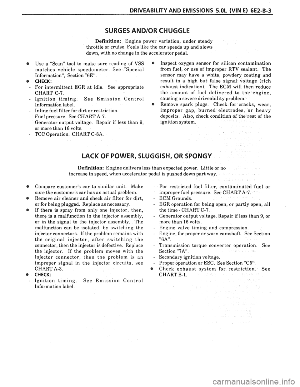
SURGES AND/OR CHUGGLE
Definition: Engine power variation, under steady
throttle or cruise. Feels like the car speeds up and slows
down, with no change in the accelerator pedal.
@ Use a "Scan" tool to make sure reading of VSS
matches vehicle speedometer. See "Special
Information", Section
"6E".
e CHECK:
- For intermittent EGR at idle. See appropriate
CHART C-7.
- Ignition timing. See Emission Control
Information label.
- Inline fuel filter for dirt or restriction.
- Fuel pressure. See CHART A-7.
- Generator output voltage. Repair if less than 9,
or more than
16 volts.
- TCC Operation. CHART C-8A.
@ Inspect oxygen sensor for silicon contamination
from fuel, or use of improper RTV sealant. The
sensor may have a white, powdery
coabing and
result in a high but false signal voltage (rich
exhaust indication). The ECM will then reduce
the amount of fuel delivered to the engine,
causing a severe driveability problem.
@ Remove spark plugs. Check for cracks, wear,
improper gap, burned electrodes, or heavy
deposits. Also, check condition of the rest of the
ignition system.
LACK OF BOWER, SLUGGISH, OR SPONGY
Definition: Engine delivers less than expected power. Little or no
increase in speed, when accelerator pedal is pushed down part way.
@ Compare customer's car to similar unit. Make - For restricted fuel filter, contaminated fuel or
sure the customer's car has an actual problem. improper fuel pressure. See CHART A-7.
@ Remove air cleaner and check air filter for dirt, - ECM Grounds.
or for being plugged. Replace as necessary.
- EGR operation for being open, or partly open, all
If there is spray from only one injector, then, the time
- CHART C-7.
there is a malfunction in the injector assembly,
- Generator output voltage. Repair if less than 9, or
or in the signal to the injector assembly.
'I'he more than 16 volts.
malfunction can be isolated, by switching the
- Engine valve timing and compression.
injector connectors.
If the problem remains with - Engine, for proper or worn camshaft. See Section
the original injector, after switching the
"6A".
connector, then the injector is defective. Replace - Transmission torque converter operation. See
the injector. If the problem moves with the
Sectionw7A".
injector connector, then the problem is an - Secondary ignition voltage.
improper signal in the injector circuits, see
- Proper operation or ESC. See Section "C5".
CHART A-3. @ Check exhaust system for restriction. See
@ CHECK: CHART B- 1.
- Ignition timing. See Emission Control
Information label.
Page 551 of 1825
6EZ-B-4 5.OL (VIN E) DRIVEABILITY AND EMISSIONS
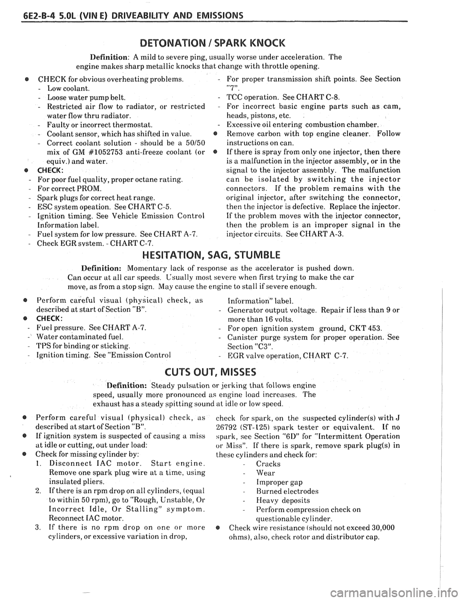
DEWNATION 1 SPARK KNOCK
Definition: A mild to severe ping, usually worse under acceleration. The
engine makes sharp metallic knocks that change with throttle opening.
@ CHECK for obvious overheatingproblems. - For proper transmission shift points. See Section
- Low coolant. "7".
- Loose water pump belt. - TCC operation. See CHART C-8.
- Restricted air flow to radiator, or restricted - For incorrect basic engine parts such as cam,
water flow thru radiator. heads,
pistons, etc.
- Faulty or incorrect thermostat. - Excessive oil entering combustion chamber.
- Coolant sensor, which has shifted in value. @ Remove carbon with top engine cleaner. Follow
- Correct coolant solution - should be a 50150 instructions on can.
mix of GM
#lo52753 anti-freeze coolant (or @ If there is spray from only one injector, then there
equiv.) and water. is
a malfunction in the injector assembly, or in the
@ CHECK: signal to the injector assembly. The malfunction
- For poor fuel quality, proper octane rating. can be isolated by switching the injector
- For correct PROM. connectors. If the problem remains with the
- Spark plugs for correct heat range.
original injector, after switching the connector,
- ESC system opeation. See CHART C-5.
then the injector is defective. Replace the injector.
- Ignition timing. See Vehicle Emission Control
If the problem moves with the injector connector,
Information label. then the
problem is an improper signal in the
- Fuel system for low pressure. See CHART A-7.
injector circuits. See CHART A-3.
- Check EGR svstem. - CHART C-7.
HESITATION, SAG, STUMBLE
Definition: Momentary lack of response as the accelerator is pushed down.
Can occur at all car speeds.
C'sually most severe when first trying to make the car
move, as from a stop sign.
May cause the engine to stall if severe enough.
@ Perform careful visual (physical) check, as Information" label.
described at start of Section
"B". - Generator output voltage. Repair if less than 9 or
@ CHECK: more than 16 volts.
- Fuel pressure. See CHART A-7. - For open ignition system ground, CKT 453.
- Water contaminated fuel. - Canister purge system for proper operation. See
- TPS for binding or sticking.
Section "C3".
- Ignition timing. See "Emission Control - EGR valve operation, CHART C-7.
CU"F OUT, MISSES
Definition: Steady pulsation or jerking that follows engine
speed, usually more pronounced as engine load increases. The
exhaust has a steady spitting sound at idle or low speed.
@ Perform careful visual (physical) check, us
described at start of Section
"B".
@ If ignition system is suspected of causing a miss
at idle or cutting, out under load:
@ Check for missing cylinder by:
1. Disconnect IAC motor. Start engine.
Remove one spark plug wire at a time, using
insulated pliers.
2. If there is an rpm drop on all cylinders, (equal
to within 50
rpm), go to "Rough, Unstable, Or
Incorrect Idle, Or Stalling" symptom.
Reconnect
IAC motor.
3. If there is no rpm drop on one or more
cylinders, or excessive variation in drop, check
for spark, on the suspected
cylinder(s) with J
26792 (ST-1251 spark tester or equivalent. If no
spark, see Section
"6D" for "Intermittent Operation
or Miss". If there is spark, remove spark plug(s) in
these cylinders and check for:
- Cracks
- Wear
- Improper gap
- Burned electrodes
- Heavy deposits
- Perform compression check on
questionable cylinder.
@ Check wire resistance (shoulcl not exceed 30,000
ohms), also, check rotor and distributor cap.
Page 555 of 1825
6EZ-C-1 5.OL (VIN E) DRIVEABILITY AND EMISSIONS
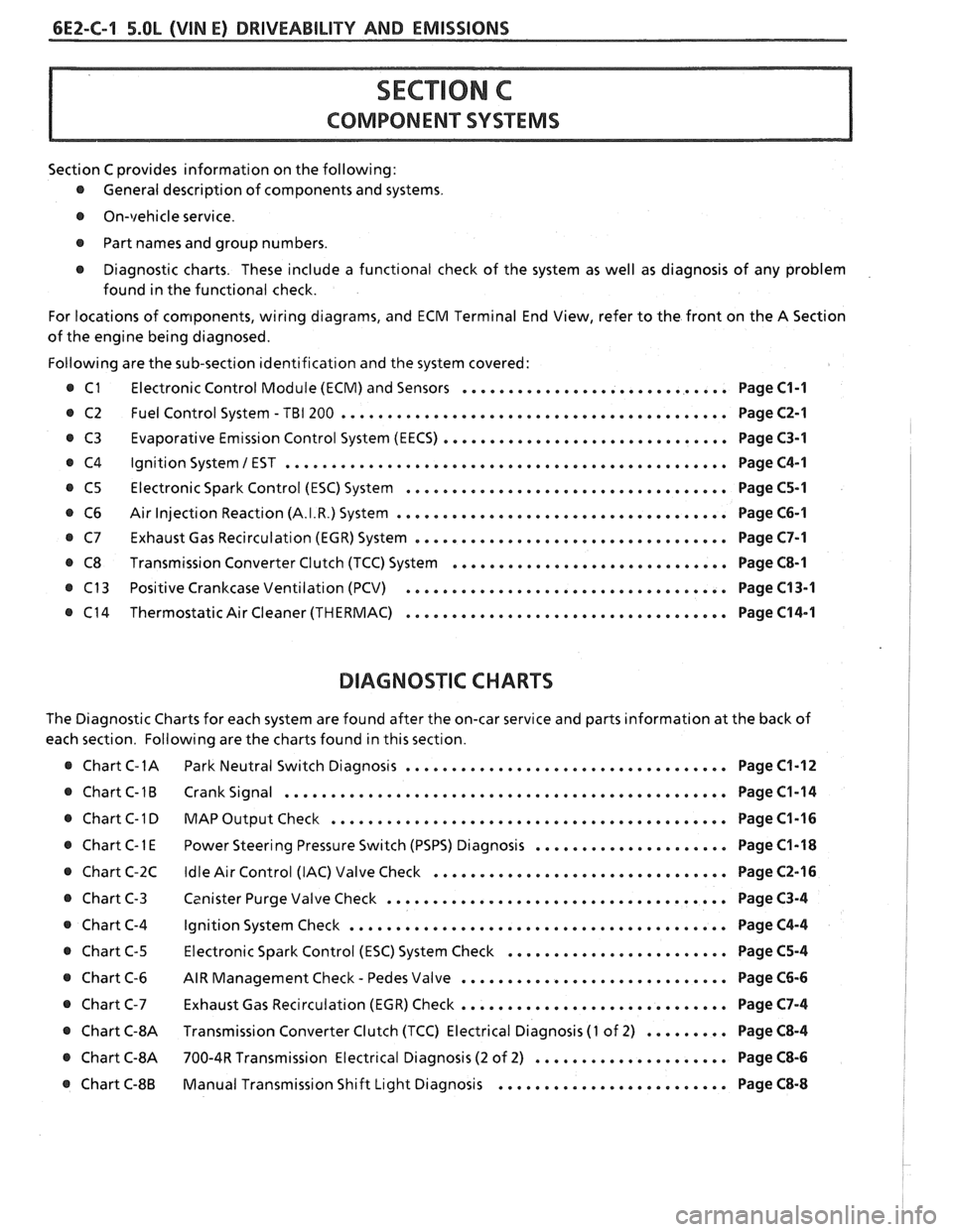
Section C provides information on the following:
@ General description of components and systems.
@ On-vehicle service.
@ Part names and group numbers.
@ Diagnostic charts. These include a functional check of the system as well as diagnosis of any problem
found in the functional check.
For locations of components, wiring diagrams, and ECM Terminal End View, refer to the front on the A Section
of the engine being diagnosed.
Following are the sub-section identification and the system covered:
@ C1 Electronic Control Module (ECM) and Sensors ............................. Page C1-1
@ C2 Fuel Control System - TBI 200 .......................................... Page C2-1
Evaporative Emission Control System (EECS) ...............................
Ignition System 1 EST ................................................
Electronic Spark Control (ESC) System ...................................
Air Injection Reaction (A.I.R.) System ....................................
Exhaust Gas Recirculation (EGR) System ..................................
Transmission Converter Clutch (TCC) System ..............................
Positive Crankcase Ventilation (PCV) ...................................
Thermostatic Air Cleaner (THERMAC) ...................................
BIAGNOSIIC CHARTS
Page C3-1
Page C4-1
Page C5-1
Page C6-1
Page C7-1
Page C8-1
Page C13-1
Page C14-1
The Diagnostic Charts for each system are found after the on-car service and parts information at the back of
each section. Following are the charts found in this section.
@ Chart C-1A Park Neutral Switch Diagnosis ................................... Page C1-12
@ Chart C-1B Crank Signal ................................................ Page C1-14
@ Chart C-1 D MAP Output Check ........................................ Page C1-16 I
..................... @ Chart C-1 E Power Steering Pressure Switch (PSPS) Diagnosis Page C1-18 1
................................ @ Chart C-2C Idle Air Control (IAC) Valve Check Page C2-16 !
..................................... @ Chart C-3 Canister Purge Valve Check Page C3-4 I
@ Chart C-4 Ignition System Check ......................................... Page C4-4
........................ @ Chart C-5 Electronic Spark Control (ESC) System Check Page C5-4
- ............................. @ Chart C-6 AIR Management Check Pedes Valve Page C6-6
............................. Chart C-7 Exhaust Gas Recirculation (EGR) Check Page C7-4
@ Chart C-8A Transmission Converter Clutch (TCC) Electrical Diagnosis (1 of 2) ......... Page C8-4 I
@ Chart C-8A 700-4R Transmission Electrical Diagnosis (2 of 2) ..................... Page C8-6 I
......................... @ Chart C-8B Manual Transmission Shift Light Diagnosis Page C8-8
Page 556 of 1825
DRIVEABILITY AND EMISSIONS 5.OL (VIN El 6EZ-C1-1
SECTION Cl
ELECTWONllC CONTROL MODULE (ECM) AND SENSORS
CONTENTS
GENERAL DESCRIPTION . . . . . . . . . . . . . . . C1-1 Coolant Temperature Sensor . . . . . . . . C1-5
ELECTRONIC CONTROL MODULE (ECM) . . C1-1 MAT Sensor. . . . . . . . . . . .. . . ... . . . . $1 -5
PROM ........................... C1-1 MAP Sensor. . . . . . . . . . . . . . . . . . . . . . C1 -6
CALPAK.........,................ C1-2 Oxygen (02) Sensor. . . . . . ... . . . a C1-6
ECM FUNCTION . . . , . . . . . . . . . . . . . . . . C1-2 Throttle Position Sensor (TPS) . . . . . . . . C1-6
INFORMATION SENSORS . . . . . . . . . . . . . C1-2 Vehicle Speed Sensor (VSS) . . . . . . . . . C1-6
Engine Coolant Temperature Sensor . . C1-2 PIN Switch. . . . . . . . . . . . . . . . . . . . . . . C1-6
MAP Sensor. . . . . . . . . . . . . . . . . . . . . . C1-2 (PSPS) . . . . . ... .. . . . ... . . .. .. . . . C1-6
MAT Sensor. . . . . . . . . . . . . . . . . . . . . . C1-3 AJC Request Signal . . . . . . . . . . . . . . . . C1-6
Oxygen (Oz) Sensor. . . . . . . . . .. . . . . . C1-3 Distributor Reference Signal . . . . . . . . . C1-6
Throttle Posit~on Sensor (TPS) . . . . . . . . C1-3 Knock Signal . . . . . . . . . . . . . . . . . . . C1-6
Knock Sensor . . . . . . . . . . . . . . . . . . . . C1-4 ON-CAR SERVICE . . . . . . . . . . . . . . . . . . . . . C1-6
Park Neutral Switch (Auto Only) . . . . . . C1-4 ELECTRONIC CONTROL MODULE . . . . . . . 61-6
Crank Signal . . . . . . , . . . . . . . . . . . . . . C1-4 PROM ........................... C1-7
A/C "On" Signal . . . , . . . . . . . . . . . . . . C1-4 Functional Check . . . . . . . . . . . . . . . . . C1-8
Vehicle Speed Sensor (VSS) . . . . . . . . . C1-4 CALPAK...................,...... C1-8
Distributor Reference Signal . . . . . . . . . C1-4 COOLANTSENSOR .. . . . . . . . , . . . . . . . . . C1-9
(PSPS) . . . . . . . . . . . . . . . . . . . . . . . . . C1-4 MAPSENSOR ..... ........ ... . .. . .* C1-9
DIAGNOSIS . . . . . . . . . . . . . . . . . . . . . . . . . C1-5 OXYGEN (02) SENSOR . . . . . . . . . a . . a . . C1-9
ECM ............................. C1-5 THROTTLE POSITION SENSOR (TPS) . . . . . C1-10
PROM ........................... C1-5 PARKINEUTRALSWITCH . . . . . . . . . . . . . . C1-10
ECM INPUTS.. . . . . . . . . . . . . . . . , . . . . . C1-5 PARTS
INFORMATION . . . . . . . . . . . . . . . . . C1-10
GENERAL DESCRIPTION
ELECTRONIC CONTROL MODULE (ECM)
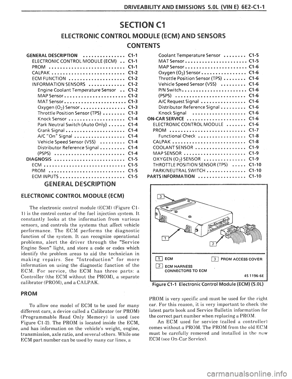
The electronic control module (KCMI (Figure C1-
1) is the control center of the fuel ir!jection system. It
constantly looks at the information from various
sensors, and controls the systems that affect vehicle
performance. The ECM performs the diagnostic
function of the system. It can recognize operational
problems, alert the driver through the "Service
Engine Soon" light, and store a code or codes which
identify the problem areas to aid the technician in
making repairs. See "Introduction" for more
information on using the diagnostic function of the
ECM. For service, the ECM has three parts:
a
Controller (the ECM without the PROM), a separate
calibrator (PROM), and a
CALPAK.
To allow one model of ECM to be used for many
different cars, a device called a Calibrator (or PROM)
(Programmable Read Only Memory) is used (see
Figure
C1-2). The PROM is located inside the ECM,
ancl has information on the vehicle's weight, engine,
transmission, axle ratio, and several others. While one
ECM part number can be used by many car lines, a
ECM PROM ACCESS COVER
1 ECM HARNESS
CONNECTORS TO ECM
45 1196-6E
Figure C1-1 Electronic Control Module (ECM) (5.OL)
PROM is very specific and must be used for the right
car. For this reason, it is very important to checlc the
latest parts book and Service Bulletin information for
the correct part number when replacing
a PROM.
An ECM used for service (called a controller)
comes without a
PROM. The PROM from the old blC>1
must be carefully removed and installctl in the new
EChI (see On-Car Service).
Page 559 of 1825
6EZ-C1-4 S.OL (VIN E) DRIVEABILITY AND EMISSIONS
THROTTLE VALVE
ENGINE CONTROL MODULE (ECM)
THROTTLE POSITION
(TPS)
8P 0321.
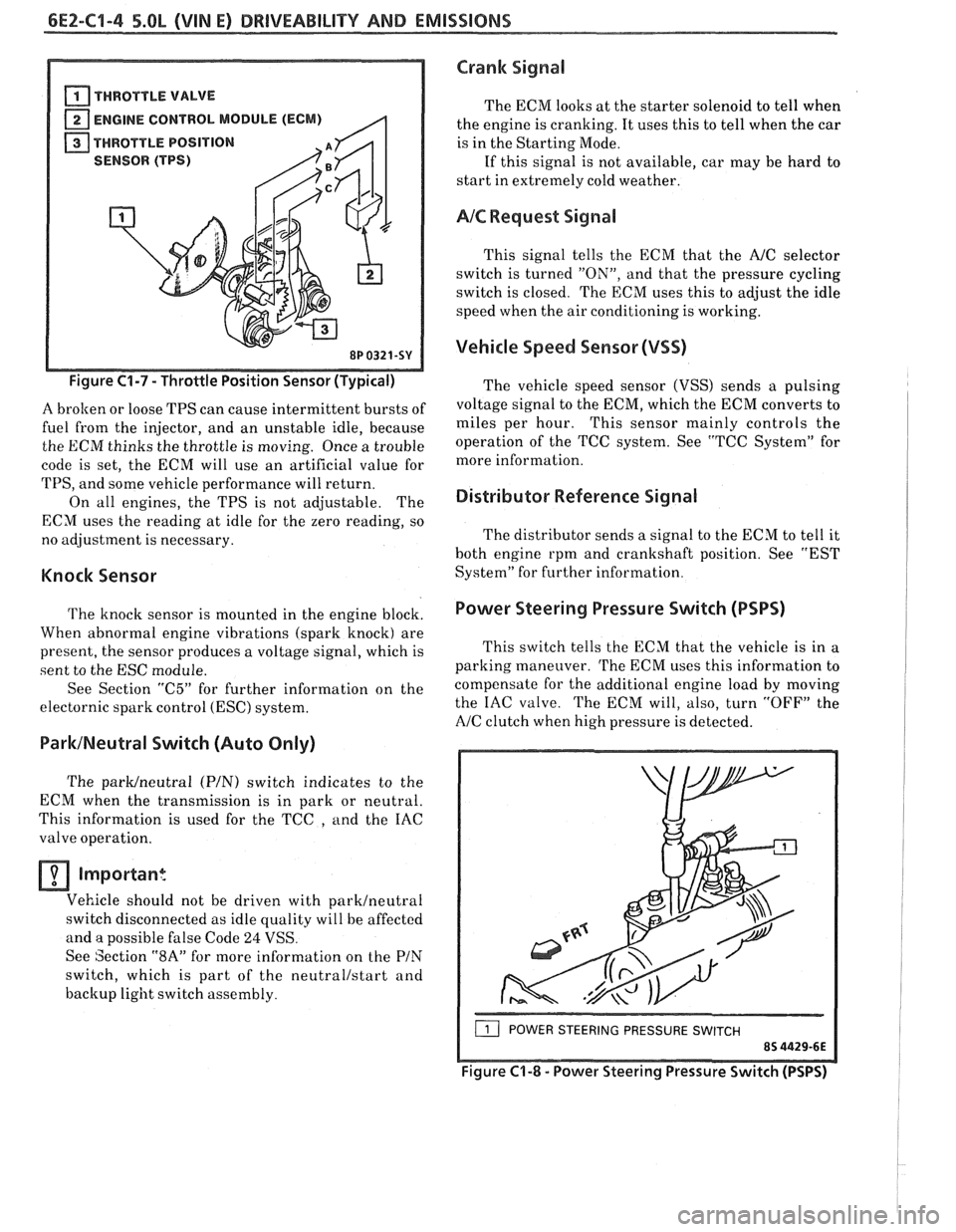
Figure C1-7 - Throttle Position Sensor (Typical)
A brolten or loose TPS can cause intermittent bursts of
fuel from the injector, and an unstable idle, because
the ECM thinks the throttle is moving. Once a trouble
code is set, the ECM will use an artificial value for
TPS, and some vehicle performance will return.
On all engines, the TPS is not adjustable. The
ECM uses the reading at idle for the zero reading, so
no adjustment is necessary.
Knock Sensor
The knock sensor is mounted in the engine block.
When abnormal engine vibrations (spark knock) are
present, the sensor produces a voltage signal, which is
sent to the ESC module.
See Section
"C5" for further information on the
electornic spark control
(ESC) system.
ParklNeutral Switch (Auto Only)
The parWneutra1 (PIN) switch indicates to the
ECM when the transmission is in park or neutral.
This information is used for the TCC
, and the IAC
valve operation.
Important
Vehicle should not be driven with parklneutral
switch disconnected as idle quality will be affected
and a possible false Code
24 VSS.
See Section
"8A" for more information on the PIN
switch, which is part of the neutrallstart and
backup light switch assembly.
Crank Signal
The ECM looks at the starter solenoid to tell when
the engine is cranking. It uses this to tell when the car
is in the Starting Mode.
If this signal is not available, car may be hard to
start in extremely cold weather.
AIC Request Signal
This signal tells the ECM that the AJC selector
switch is turned
"ON", and that the pressure cycling
switch is closed. The ECM uses this to adjust the idle
speed when the air conditioning is working.
Vehicle Speed Sensor (VSS)
The vehicle speed sensor (VSS) sends a pulsing
voltage signal to the ECM, which the ECM converts to
miles per hour. This sensor mainly controls the
operation of the TCC system. See "TCC System" for
more information.
Distributor Reference Signal
The distributor sends a signal to the ECM to tell it
both engine rpm and crankshaft position. See "EST
System" for further information.
Power Steering Pressure Switch (PSPS)
I
This switch tells the ECM that the vehicle is in a
parking maneuver.
The ECM uses this information to
compensate for the additional engine load by moving
the IAC valve. The ECM will, also, turn
"OFF" the
A/C clutch when high pressure is detected.
( POWER STEERING PRESSURE SWITCH
Figure C'I-8 - Power Steering Pressure Switch (PSPS)
Page 567 of 1825
6E2-C1-12 DRlVEABlLllV AND EMISSIONS - 5.OL (VIN E)
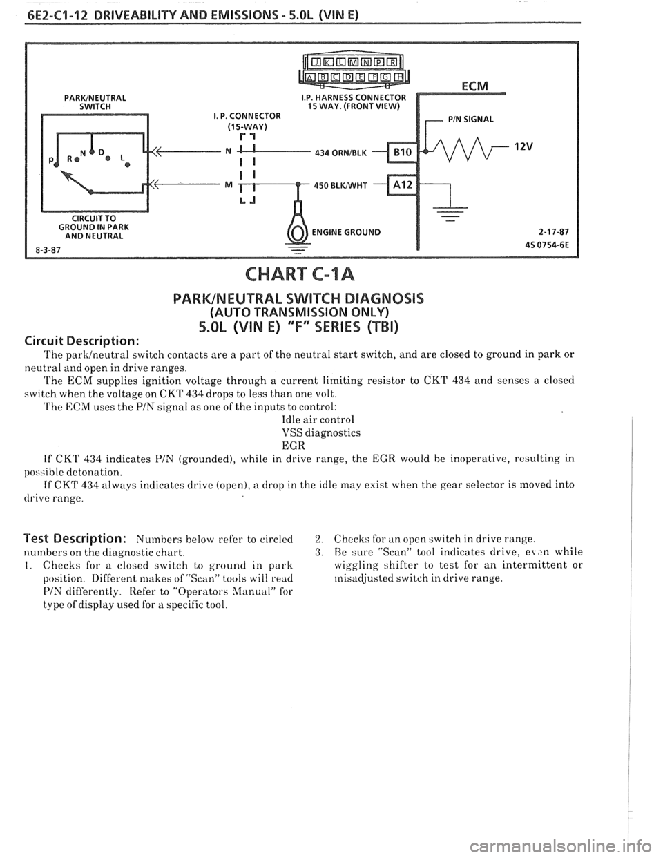
434 ORNIBLK
450 BLWHT
ENGINE GROUND
CHART C-lA
PARWNEUTRAL SWIKC DIAGNOSIS
(AUTO TRANSMISSION ONLY)
5.0L (VIN E) ""FYmSERIES (TBI)
Circuit Description:
The parklneutral switch contacts are a part of the neutral start switch, and are closed to ground in park or
neutral and open in drive ranges.
The ECM supplies ignition voltage through a current limiting resistor to CKT 434 and senses a closed
switch when the voltage on CKT
434 drops to less than one volt.
The ECM uses the PIN signal as one of the inputs to control:
Idle air control
VSS diagnostics
EGR
If CKT
434 indicates PIN (grounded), while in drive range, the EGR would be inoperative, resulting in
possible detonation.
If CKT
434 always indicates drive (open), a drop in the idle may exist when the gear selector is moved into
drive range.
Test Description: Numbers below refer to circled 2. Checks for an open switch in drive range.
numbers on the diagnostic chart.
3. Be sure "Scan" tool indicates drive, el ,tn while
I. Checks for a closed switch to ground in park wiggling
shifter to test for an intermittent or
position.
Iliffercnt lrlakes of "Scan" tools will rend ~nisadjusted switch in drive range.
PIS differently. Refer to "Operators Slanuul" for
type of display used for a specific tool.
Page 584 of 1825
DRIVEABILITY AND EMISSIONS - 5.OL (VIN El CEZ-C2-9
u PART IDENTIFICATION NUMBER
VENDOR IDENTlFlCATl
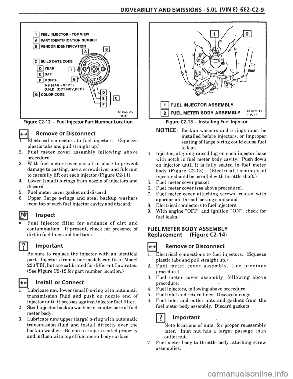
Figure C2-12 - Fuel Injector Part Number Location
Remove or Disconnect
lectrical connectors to fuel injectors. (Squeeze
plastic tabs and pull straight
up.)
2. Fuel meter
cover assembly following above
procedure.
3. With fuel meter cover gasket in place to prevent
damage to casting, use a screwdriver and fulcrum
to carefully lift out each injector (Figure
C2-11).
4. Lower (small) o-rings from nozzle of injectors and
discard.
5. Fuel meter cover gasket and discard.
6. Upper (large o-rings and steel backup washers
from top of each fuel injector cavity and discard.
Inspect
@ Fuel injector filter for evidence of dirt and
contamination.
If present, check for presence of
dirt in fuel lines and fuel tank.
Important
Be sure to replace the injector with an identical
part. Injectors from other models can fit in Model
220 TBI, but are calibrated for different flow rates.
(See Figure
C2-12 for part number location.)
Install or Connect
1. Lubricate new lower (small) o-ring with automatic
transmission fluid and push on nozzle end of
injector until it presses against
in,jector fuel filter.
2. Steel injector backup washer in counterbore of fuel
meter body.
3. Lubricate new upper (large) o-ring with automatic
transmission fluid and install directly over
the
backup washer. Be sure o-ring is seated properly
and is flush with top of fuel meter body surface.
I I 1 I FUEL INJECTOR ASSEMBLY
FUEL METER BODY ASSEMBLY
~p,~9~~~As
Figure C2-13 - Installing Fuel Injector
NOTICE: Backup washers and o-rings must be
installed before injectors, or improper
seating of large o-ring
could cause fuel
to leak.
4. Injector, aligning raised lug on each injector base
with notch in fuel meter body cavity. Push down
on injector until it is fully seated in fuel meter
body (Figure
C2-13). (Electrical terminals of
injector should be parallel with throttle shaft.)
5. Fuel meter cover gasket.
6. Fuel meter cover (see above procedure).
7. Fuel meter cover attaching screws, coated with
appropriate thread locking compound.
8. Electrical connectors to fuel injectors.
9. With engine "OFF" and ignition "ON", check for
fuel leaks.
FUEL METER BODY ASSEMBLY
Replacement (Figure
CZ-14)
a Remove or Disconnect
1. Electrical connections to fuel injectors. (Squeeze
plastic tabs and pull straight up.)
2. Fuel meter cover assembly, (see previous
procedure).
3. Fuel
meter cover assembly, following above
procedure.
4. Fuel injectors, following above procedure.
5. Fuel inlet and return lines. Discard o-rings.
6. Fuel inlet and outlet nuts and gaskets from the
fuel meter body assembly. Discard gaskets.
Important
Note locations of nuts, for proper reassembly
later. Inlet nut has a larger passage than
outlet nut.
7. Fuel meter body to throttle body attaching screw
assemblies.