1988 PONTIAC FIERO transmission
[x] Cancel search: transmissionPage 712 of 1825
DRIVEABILITY AND EMISSIONS 2.8L (VIN S) 6E3-B-3
e A faulty in-tank fuel pump check valve will @ If engine starts but then immediately stalls,
allow the fuel in the lines to drain back to the open
distributor by-pass line. If engine then
tank after the engine is stopped. To check for starts
and runs OK, replace pickup coil.
this condition:
@ If engine starts and stalls, disconnect MAF
Perform Fuel System Diagnosis, CHART A-7. sensor. If engine then runs and sensor
@ Remove spark plugs. Check for wet plugs, connections are OK, replace the sensor.
cracks, wear, improper gap, burned
f lectrodes,
or heavy deposits. Repair or replace as
necessary.
HESITATION, SAG, STUMBLE
Definition: Momentary lack of response as the accelerator is pushed down. Can
occur at all car speeds.
Usually most severe when first trying to make the car move, as
from a stop sign. May cause the engine to stall if severe enough.
Perform careful visual check as described at
start of Section
"B".
a CHECK:
- Fuel pressure. See CHART A-7. Also check for
water contaminated fuel.
- Air leaks at air duct between MAF sensor and
throttle body.
- Spark plugs for being fouled or faulty wiring.
- PROM (2.8L) or MEM-CAL (5.OL & 5.7L)
number. Also check service bulletins for latest
MEM-CAL or PROM.
- TPS for binding or sticking. Voltage should
increase at a steady rate as throttle is moved
toward WOT.
- Ignition timing. See Emission Control
Information label.
- Generator output voltage. Repair if less than 9
or more than 16 volts.
- HE1 ground, CKT 453.
- Canister purge system for proper operation.
See CHART C-3.
- EGR - See CHART C-7.
@ Perform injector balance test CHART C-2A.
SURGES AND/OR CHUGGLE
Definition: Engine power variation under steady
throttle or cruise. Feels like the car speeds up and
slows down with no change in the accelerator pedal.
Be sure driver understands transmission
converter clutch and
A/C compressor operation
in Owner's Manual.
e Perform careful visual inspection as described
at start of Section
"B".
CHECK:
- TCC and 4th gear switch operation - See
CHART C-8A.
- Loose or leaking air duct between MAF sensor
and throttle body.
- Generator output voltage. Repair if less than 9
or more than 16 volts.
- EGR - There should be no EGR at idle. See
CHART C-7. Also check for plugged EGR
solenoid filter.
- Vacuum lines for kinks or leaks.
- Ignition timing. See Emission Control
Information label.
- In-line fuel filter. Replace ifdirty or plugged.
- Fuel pressure while condition exists. See
CHART A-7.
@ Inspect oxygen sensor for silicone contamination
from fuel, or use of improper RTV sealant. The
sensor may have a white, powdery coating and
result in a high but false signal voltage (rich
exhaust indication). The ECM will then reduce
the amount of fuel delivered to the engine,
causing a severe driveability problem.
@ Remove spark plugs. Check for cracks, wear,
improper gap, burned electrodes, or heavy
deposits. Also check condition of distributor cap,
rotor, and spark plug wires.
@ To help determine if the condition is caused by a
rich or lean system, the car should be driven at
the speed of the complaint. Monitoring block
learn at the complaint speed will help identify the
cause of the problem. If the system is runnig lean
(block learn greater than
138), refer to
"Diagnostic Aids" on
facing page of Code 44. If
the system is running rich (block learn less than
118), refer to "Diagnostic Aids" on facing page of
Code 45.
Page 719 of 1825
6E3-C-1 2.8L (VIN S) DRIVEABILITY AND EMISSIONS
COMPONENT SYSTEMS
Section C provides information on the following:
@ General description of components and systems .
e On-vehicle service .
@ Part names and group numbers .
@ Diagnostic charts . These include a functional check of the system as well as diagnosis of any problem
found in the functional check
.
For locations of components. wiring diagrams and ECM Terminal End View refer to the front of the A Sections of
the engine being diagnosed
.
Following are the sub-section identification and the system covered:
Electronic Control Module (ECM) and Sensors
........................... Page C1-I
Fuel Control System ............................................... Page C2-1
Evaporative Emission Control (EECS) System ............................ Page C3-1
Ignition SystemIEST ............................................... Page C4-1
Air Injection Reaction (A.I.R.) System Manual Transmission Only .............. Page C6-1
Exhaust Gas Recirculation (EGR) System ................................ Page C7-1
Transmission Converter Clutch (TCC) System and Manual Transmission Shift Light Page C8-1
ECM Controlled Air Conditioning .................................... Page C10-I
Cooling Fan Control ............................................... Page C12-1
Positive Crankcase Ventilation (PCV) .................................. Page C13-1
DIAGNOSTIC CHARTS
The Diagnostic Charts for each system are found after the on-car service and parts information at the back of
each section
. Following are the charts found in this section .
@ Chart C-I
@ Chart C-1A
e ChartC-1E
@ Chart C-2A
e Chart C-2C
@ Chart C-3
@ Chart C-4A
@ Chart C-6
@ Chart C-7
@ Chart C-8
@ Chart C-8
@ Chart C-10
@ Chart C-12
@ Chart C-12 ECM
QDR Check ........................................... Page C1-10
Park
Neutral Switch ........................................ Page C1-12
Power Steering Pressure Switch Check .......................... Page C1-14
Injector Balance Test ....................................... Page C2-18
Idle Air Control ........................................... Page C2-20
Canister Purge Valve Check .................................. Page C3-4
Ignition System Check ...................................... Page C4-4
Electric Control (Divert) . (Manual Transmission) .................. Page C6-6
Exhaust Gas Recirculation Check .............................. Page C7-6
Automatic Transmission Converter Clutch (TCC) . 1 of 2 ............. Page C8-2
Automatic Transmission Converter Clutch (TCC) . 2 of 2 ............. Page C8-4
NC Clutch Control ......................................... Page C10-2
. ............. ............... Cooling Fan Control Circuit 1 of 2 Page C12-2
. ............................. Cooling Fan Control Circuit 2 of 2 Page C12-4
Page 721 of 1825
6E3-C1-2 2.8L (VIN S) DRIVEABILITY AND EMISSIONS
transmission, axle ratio, and several others. While one
ECM part number can be used by many car lines, a
PROM is very specific and must be used for the right
car. For this reason, it is very important to check the
latest parts book and Service Bulletin information for
the correct part number when replacing a PROM.
An ECM used for service (called a controller)
comes without a PROM. The PROM from the old ECM
must be carefully removed and installed in the new
ECM (see On-Car Service).
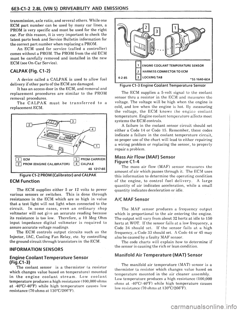
CALPAK (Fig. C1-2)
A device called a CALPAK is used to allow fuel
delivery if other parts of the ECM are damaged.
It has an access door in the ECM, and removal and
replacement procedures are similar to the PROM
removal procedures.
The CALPAK must be transferred to a
replacement ECM.
M (ENGINE CALIBRATOR)
Figure C1-2 PROM (Calibrator) and CALPAK
ECM Function
The ECM supplies either 5 or 12 volts to power
various sensors or switches. This is done through
resistances in the ECM which are so high in value
that
a test light will not light when connected to the
circuit. In some cases, even an ordinary shop
voltmeter will not give an accurate reading because
its resistance is too low. Therefore, a 10
Meg Ohm
input impedance digital voltmeter is required to
assure accurate voltage readings.
The ECM controls output circuits such as the
Injector, IAC, Cooling Fan Relay, etc. by controlling
the ground circuit
thr0ug.h transistors in the ECM.
Engine Coolant Temperature Sensor
(Fig.CI-3)
The coolant sensor is a thermistor (a resistor
which changes value based on temperature) mounted
in the engine coolant stream.
Low coolant
temperature produces a high resistance
( 100,000 ohms
at -40°C/-40°F) while high temperature causes low
resistance (70 ohms at
130"C/26fi°F).
ENGINE COOLANT TEMPERATURE SENIOR
HARNESS CONNECTOR TO ECM
4-2-85 LOCKING TAB *5S 4640-6EA
Figure C1-3 Engine Coolant Temperature Sensor
The ECM supplies a 5-volt signal to the coolant
sensor thru a resistor in the ECM
and measures thc
voltage. The voltage will be high when the engine is
cold, and
low when the engine is hot. t3y measuring
the voltage, the ECM knows
the engiao coo/ant
temperature. Engine coolant temperature aifeces most
systems the ECM controls.
A failure
in the coolant sensor circuit should set
either a Code 14 or Code 15. Remember, these codes
indicate a failure in the coolant temperature circuit,
so proper use of the chart will
lead to either repairing
a wiring problem or replacing the sensor, to properly
repair a problem.
Mass Air F10w (MAF) Sensor
Figure C1-4
The mass air flow (MAF) sensor measures the
amount of air which passes through it.
'I'he ECM uses
this information to determine the operating condition
of the engine, to control
fuel delivery. A large
quantity of air indicates acceleration, while a small
quantity indicates deceleration or idle.
NC MAF Sensor
'I'he MAF sensor produces a frequency output
which is proportional to the air entering the en,'
alne.
The output will vary from about 32 hertz at idle to 150
hertz at WOT. If the sensor fails at a low frequency, a
Code 34 should set. If the sensor fails at a high
frequency, a
Code 33 should set. A Code 44 or 45 may
also be caused by a faulty
MAF sensor.
'I'he code charts will explain how to determine if
the sensor is causing the rich or lean condition.
Manifold Air Temperature (MAT) Sensor
The manifold air temperature (MAT) sensor is a
thermistor
(a resistor which changes value based on
temperature mounted in the
air cleaner assembly.
1,ow temperature produces a high resistance (100,000
ohms at -40°C/-400F) while high temperature causes
low resistance (70 ohms at
130"C/2G6"F).
Page 723 of 1825
6E3-Cl-4 2.8L (VIN S) DRIVEABILITY AND EMISSIONS
BarWNeutral Switch (Auto Only)
The ParWNeutral (PIN) switch indicates to the
ECM when the transmission is in Park or Neutral.
This information is used for the TCC and the IAC
valve operation.
Important
Vehicle should not be driven with ParWNeutral
switch disconnected as idle quality will be affected
and a possible false Code
24 (VSS).
See Section "$A" for more information on the PIN
switch, which is part of the neutrallstart and backup
light switch assembly.
NC '"n" Signal
This signal tells the ECM that the A/C selector
Switch is turned on, and that the pressure cycling
switch is closed. The ECM uses this to adjust the idle
Speed when the air conditioning is working.
If this signal is not available to the ECM, idle may
be rough, especially when the
A/C compressor cycles.
The voltage at ECM terminal "B8" should equal
battery voltage when
AIC is requested and the
pressure cycling switch is closed.
The signal at
B8 will cause the ECM to turn on the
A/C clutch by energizing the A/C relay.
Distributor Reference Signal
The distributor sends a signal to the ECM to tell it
both engine RPM and crankshaft position. See EST
System for further information.
To read the codes, use a "Scan" tool or ground the
diagnostic terminal with the engine not running and
the ignition on. The "Service Engine Soon" light will
flash Code 12 three times and
then flash each code
stored in memory three times. All codes stored in
memory would have been read when Code 12 was
flashed again. No new codes can be stored when in the
Diagnostics Mode (diagnostics lead grounded).
This
eliminates confusion while the system is being worked
on. To clear the codes from memory:
@ Ignition off
@ Remove fuse located in a weather proof holder
located near the battery for 30 seconds.
Since the ECM can have
a failure which may
effect only one circuit, following the Diagnostic
Procedures in this section will determine which circuit
has a problem and where it is. If
a diagnostic chart indicates that the ECM
connections or ECM is the cause of
a problem and the
ECM is replaced, but does not correct the problem, one
of the following may be the reason:
€9
connections. - The diagnostic chart will say "ECM
connections or ECM. The terminals may have to be
removed from the connector in order to check them
properly.
@ The ECM or PROM is not correct for the
application.
- The incorrect components may cause a
malfunction and may or may not set a code.
@ The problem is intermittent. - This means that
the problem is not present at the time the system is
being checked. In this case, refer to the "Symptoms"
portion of the manual and make a careful physical
inspection of all portions of the system involved.
@ Shorted solenoid, relay coil, or harness. -
Solenoids and relays are turned "ON" and "OFF" by
the
ECM,using internal electronic switches called
"Drivers". Each driver is part of
a group of four called
"Quad-drivers". Failure of one driver can damage any
other driver in the set.
Solelloid and relay coil
resistance must measure more than 20 ohms. Less
resistance will cause early failure of the ECM
"driver". A shorted solenoid, relay coil, or harness,
with a GMP4 computer, will not damage the ECM, but
will cause the component to be inoperative.
Before replacing an ECM, be sure to check the coil
resistance of all solenoids and relays controlled by the
ECM. See ECM wiring diagram for the
solenoid(s)
and relay(s) and the coil terminal identification.
534636 or BT 8405 testers or equivalent provide
a fast, accurate means of checking for a shorted coil or
a short to battery voltage.
@ The PROM may be faulty. - Although these
rarely fail, it operates as part of the ECM. Therefore,
it could be the cause of the problem. Substitute a
known good PROM.
@ The replacement ECM may be faulty. - After the
ECM is replaced, the system should be rechecked for
proper operation. If the diagnostic chart again
indicates the ECM is the problem, substitute
a known
good ECM. Although this is a rare condition, it could
happen.
ECM
A faulty ECM will be determined in the diagnostic
charts or
by a Code 55.
PROM
A faulty PROM may result in a Code 51.
Page 749 of 1825
6E3-CZ-14 2.8L (VIN S) DRlVEABlLlTV AND EMISSIONS
MINIMUM IDLE SPEED ADJUSTMENT
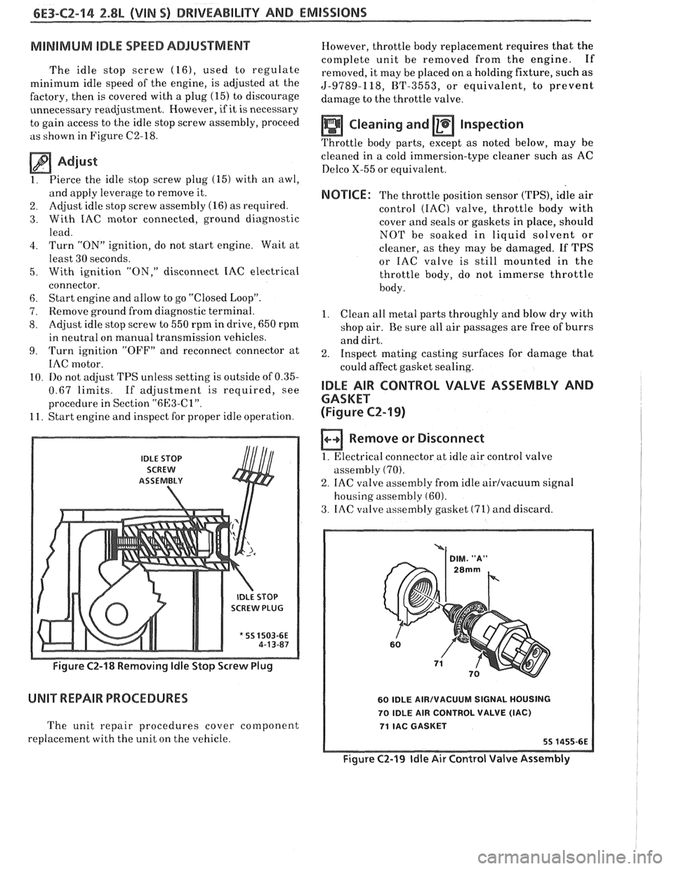
The idle stop screw (16), used to regulate
minimum idle speed of the engine, is adjusted at the
factory, then is covered with a plug
(15) to discourage
unnecessary readjustment. However,
if it is necessary
to gain access to the idle stop screw assembly, proceed
as shown in Figure C2-18.
Adjust
1. Pierce
the idle stop screw plug (15) with an awl,
and apply leverage to remove it.
2. Adjust idle
stop screw assembly (16) as required.
3. With IAC motor connected, ground diagnostic
lead.
4. Turn "ON" ignition, do not start engine. Wait at
least 30 seconds.
5. With ignition "ON," disconnect IAC electrical
connector.
6. Start engine and allow to go "Closed Loop".
7. Remove ground from diagnostic terminal.
8. Adjust idle stop screw to 550 rpm in drive, 650 rpm
in neutral on manual transmission vehicles.
9. Turn ignition "OFF7' and reconnect connector at
IAC motor.
10.
110 not adjust TPS unless setting is outside of 0.35-
0.67 limits. If adjustment is required, see
procedure in Section
"6l33-Cl".
11. Start engine and inspect for proper idle operation.
IDLE STOP
SCREW
ASSEtVIBLY
SCREW PLUG
* 55 1503-6E
Figure C2-18 Removing ldle Stop Screw Plug
UNIT REPAIR PROCEDURES
The unit repair procedures cover component
replacement with the unit on the vehicle. However,
throttle body replacement requires that the
complete unit be removed from the engine. If
removed, it may be placed on a holding fixture, such as
5-9789-118, BT-3553, or equivalent, to prevent
damage to the throttle valve.
Cleaning and Inspection
Throttle body parts, except as noted below, may be
cleaned in
a cold immersion-type cleaner such as AC
Delco X-55 or equivalent.
NOTICE: The throttle position sensor (TPS), idle air
control
(IAC) valve, throttle body with
cover and seals or gaskets in place, should
NOT be soaked in liquid solvent or
cleaner, as they may be damaged. If TPS
or IAC valve is still mounted in the
throttle body, do not immerse throttle
body.
1. Clean
all metal parts throughly and blow dry with
shop air. Be sure all air passages are free of burrs
and dirt.
2. Inspect mating casting surfaces for damage that
could affect gasket sealing.
IDLE AIR CONTROL VALVE ASSEMBLY AND
GASKET
(Figure
CZ-19)
Remove or Disconnect
1. Electrical connector at idle air control valve
assembly
(70).
2. IAC valve assembly from idle airlvacuum signal
housing assembly
(60).
3. IAC valve assembly gasket (71) and discard.
60 IDLE AIRIVACUUM SIGNAL HOUSING
70 IDLE AIR CONTROL VALVE
(IAC)
71 IAC GASKET
Figure C2-19 ldle Air Control Valve Assembly
Page 770 of 1825
DRIVEABILITY AND EMISSIONS 2.8L (VIN S) 6E3-C6-4
SECTION C6
AIR INJECTION REACTlON (A.I.R.) SYSTEM
MANUAL, TRANSMISSION ONLY
CONTENTS
............... GENERAL DESCRIPTION C6-1
........................ PURPOSE C6-1
........... A.I.R. PUMP OPERATION.. C6-1
................... AIR CONTROL.. C6-1
.......... Electric Air Control Valve C6-1
............... Deceleration Valve C6-2
... RESULTS OF INCORRECT OPERATION C6-2
........................ DIAGNOSIS C6-2
............. OPERATIONAL CHECKS C6-2
.................... A.I.R. Pump C6-2
GENERAL DESCRlPTlON
PURPOSE
These systems are used to reduce carbon monoxide
(CO), hydrocarbon (HC) and oxides of nitrogen (NO,)
emissions. They also heat up the catalytic converter
quickly "ON" engine start-up so conversion of exhaust
gases will start quickly.
A.I.R. PUMP OPERATION
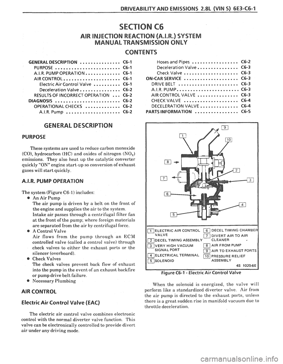
The system (Figure C6-1) includes:
@ An Air Pump
The air pump is driven by a belt on the front of
the engine and supplies the air to the system.
Intake air passes through a centrifugal filter fan
at the front of the pump; where foreign materials
are separated from the air by centrifugal force.
@ A Control Valve
Air flows from the pump through an
ECM
controlled valve (called a control valve) through
check valves to either the exhaust ports or the
silencer (overboard).
@ Check Valves
The check valves prevent back flow of exhaust
into the pump in the event of an exhaust backfire
or pump drive belt failure.
@ Necessary Plumbing
AIR CONTROL
Electric
Air Control Valve (EAC)
................. Hoses and Pipes C6-2
............. Deceleration Valve.. C6-3
.................... Check Valve C6-3
.................... ON-CAR SERVICE C6-3
................... DRIVE BELT ... C6-3
............... A.I.R.PUMP.....,.. C6-3
............... AIR CONTROL VALVE C6-3
.................... CHECK VALVE C6-4
............ DECELERATION VALVE.. C6-4
................ PARTS INFORMATION C6-5
ELECTRIC AIR CONTROL 1 DECELTIMING CHAMBEF VALVE 1 DIVERT AIR TO AIR
~DECEL TIMING ASSEMBLY CLEANER
VERY HIGH VACUUM 1 AIR FROM PUMP
SIGNAL PORT 1 AIR TO EXHAUST PORTS
14~~c~R1cA~~~RM1NAL 1 PRESSURE RELIEF ~SOLENOID ASSEMBLY
4s 1020-6E
Figure C6-1 - Electric Air Control Valve
When the solenoid is energized, the valve will
perform like a standardized diverter valve. Air
from
the air pump is directed to the exhaust ports, unless
there is a great sudden rise in manifold vacuum due to
throttle deceleration.
The electric air control valve combines electronic
control with the normal diverter valve function. This
valve can be electronically controlled to provide divert
air under any driving mode.
Page 775 of 1825
6E3-C6-6 2.8L (VIN S) DRlVEABlLlTY AND EMISSIONS
AIR SOLENOID
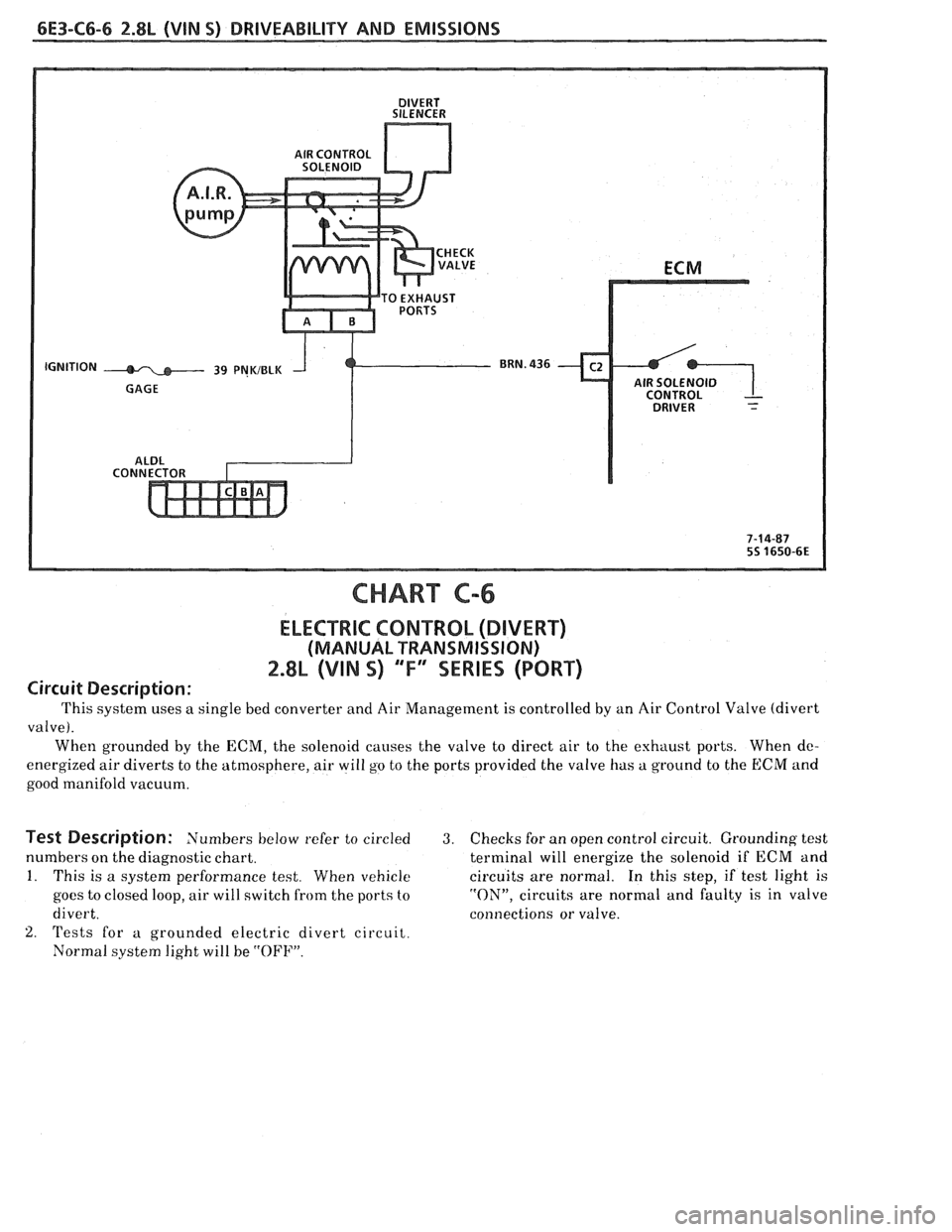
CHART C-6
ELECTRIC CONTROL (DIVERT)
(MANUAL TRANSMISSION)
2.8L (VIN S) "'F" SERIES (PORT)
Circuit Description:
This system uses a single bed converter and Air Management is controlled by an Air Control Valve (divert
valve).
When grounded by the ECM, the solenoid causes the valve to direct air to the exhaust ports. When
dc-
energized air diverts to the atmosphere, air will go to the ports provided the valve has a ground to the ECM and
good manifold vacuum.
Test Description: Numbers below refer to circled 3. Checks for an open control circuit. Grounding test
numbers on the diagnostic chart. terminal will energize the solenoid if ECM and
1. This is a system performance test. When vehicle circuits are normal. In this step, if test light is
goes to closed loop, air will switch from the ports to "ON", circuits are normal and faulty is in valve
divert. connections or valve.
2. 'rests for a grounded electric divert circuit.
Normal system light will be
"OFF".
Page 786 of 1825
DRIVEABILITY AND EMlSSlONS 2.8L (VIN %I 6E3-C8-1
TRANSMISSION CONVERTER CLUTCH (KC) SYSTEM
AND MANUAL
TRANSMISSION SHIFT LIGHT
CONTENTS
GENERAL DESCRIPTION ................ C8-1 DIAGNOSIS ..........ee...ee....e.e. C8-1
PURPOSE ......................... C8-1 SHIFT LIGHT (MIT) DESCRIPTION ........ C8-1
OPERATION ....................... C8-1 DIAGNOSIS ....................... .. C8-1
ON-CAR SERVICE ...................*. C8-1
GENERAL DESCRIPTION
PURPOSE
The transmission converter clutch (TCC) svstem
uses a solenoid operated valve in the automatic
transmission to couple the engine flywheel to the
output shaft of the transmission thru the torque
converter. This reduces the slippage losses in the
converter, which increases fuel economy.
OPERATION
For the converter clutch to apply, two conditions
must be met:
o Internal transmission fluid pressure must be
correct. For information on internal transmission
operation, see Section
"7A". This section will cover
only the electrical operation of the TCC system.
@ The ECM grounds a switch internally to turn on a
solenoid in the transmission. This moves a check
ball, which will allow the converter clutch to
apply, if the hydraulic pressure is correct, as
described above.
The ECM controls the TCC apply solenoid by
looking at several sensors:
@ Speedo Buffer Sensor (also called vehicle speed
sensor
(VSS). Speed must be above a certain value
before the clutch can apply.
@ Coolant Temperature Sensor. Engine must be
warmed up before clutch can apply about
65OC
(149°F').
Throttle position sensor ('I'PS). After the
converter clutch applies, the
HCM uses the
information from the TPS to release thc clutch
when the car is accelerating or decelerating at a
certain rate.
@ 'I'he brake switch is also part of the 'I'CC circuit as
it will remove battery voltage to the 'KC solenoid
when the brake pedal is depressed.
@ Gear Select Switch. The 4th gear switch is used to
send a signal to the
ECM telling it when the
transmission is in 4th gear. The ECM uses this
information to vary the conditions under which
the clutch applies or releases.
IIowever, the
transmission does not have to be in fourth gear in
order for the ECM to turn the clutch on.
If the converter clutch is applied at all times. the
engine will stall immediately, just as in
u manual
transmission with the clutch applied.
If the converter clutch does not apply, fuel
ecomony
may be lower than expected. If the vehicle
speed sensor fails, the TCC will not apply. If the 4th
gear switch does not operate, the TCC may not apply
at the right time.
DIAGNOSIS
The diagnosis of the TCC system is covered in
CHART C-8
. If the ECM detects a problem in the
system,
a Code 24 should set. In this case see Code 24
CHART.
SHIFT LIGHT (MiT) DESCRIPTION
'The purpose of the shift light is to provide a
display which indicates the optimum fuel economy
point for up
shifling the manual transmission based
on engine speed
and load. 'I'he display is a lamp on the
instrument panel. Activation of the ECM driver turns
the lamp
on.
'I'he shift light circuit can he checlted using
CHAR?' C-8C.
ON-CAR SERVICE
@ See Section "8B" if the shift light bulb needs
replacement.
@ See Section "6E" to repair wiring problem.
@ See Section "6C" if ECM is to be replaced.