1988 PONTIAC FIERO transmission
[x] Cancel search: transmissionPage 787 of 1825
6E3-C8-2 2.8L (VIN S) DRIVEABILITY AND EMISSIONS
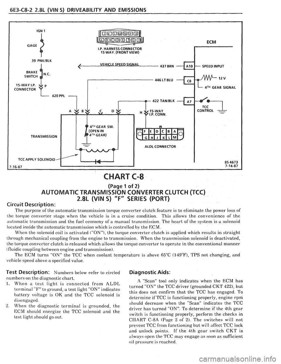
VEHICLE SPEED SIGNAL
SPEED INPUT
CONNECTOR
aTH GEAR SIGNAL
422 TAN/BLK
4TH GEAR SW.
TRANSMISSION
ALDL CONNECTOR
TCC APPLY SOLENOID
CHART C-8
(Page 1 of 2)
AUWBMATIC TRANSMISSION CONVERTER CLUTCH (TCC)
2.8L (VIN S) "F" SERIES (PORT)
Circuit Description:
The purpose of the automatic transmission torque converter clutch feature is to eliminate the power loss of
the torque converter stage when the vehicle is in a cruise condition. This allows the convenience of the
automatic transmission and the fuel economy of a manual transmission. The heart of the system is
a solenoid
located inside the automatic transmission which is controlled by the
ECM.
When the solenoid coil is activated ("ON"), the torque converter clutch is applied which results in straight
through mechanical coupling from the engine to transmission. When the transmission solenoid is deactivated,
the torque converter clutch is released which allows the torque converter to operate in the conventional manner
(fluidic coupling between engine and transmission).
The ECM turns
"ON" the 'KC when coolant temperature is above 65°C (14g°F), TPS not changing, and
vehicle speed above a specified value.
Test Description: Numbers below refer to circled Diagnostic Aids:
numbers on the diagnostic chart. A "Scan" tool only indicates when the ECM has 1. When a test light is connected from ALDL turned the TCC driver (grounded CKT 422), but terminal "F" to ground, a test light "ON" indicates
this does not confirm that the TCC has engaged. To battery voltage is OK and the TCC solenoid is
determine if TCC is functioning properly, engine rpm
disengaged.
should decrease when the "ScanJ' indicates the TCC
2. When the diagnostic terminal is grounded, the
driver has turned "ON". To determine if the 4th gear ECM energize the TCC "Ienoid and the switch is functioning properly, perform the checks in
test light should go out.
CIIART C-8A (Page 2 of 2). The switches will not
prevent TCC fi-om functioning but will affect TCC lock
and unlock points. If the 4th gear switch CKT is
always open the
TCC may engage as soon as sufficient
oil
pl.essure is reached.
Page 789 of 1825
6E3-C8-4 2.8L (VIN 5) DRIVEABILITY AND EMISSIONS
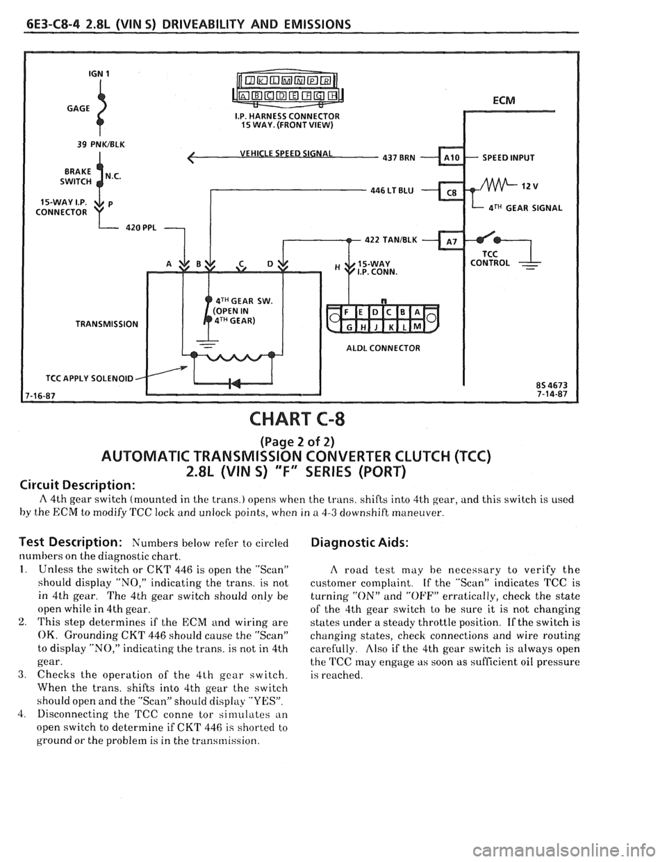
VEHICLE SPEED SIGNAL
4TH GEAR SIGNAL
422 TANIBLK
4TH GEAR SW.
TRANSMISSION
ALDL CONNECTOR
TCC APPLY SOLENOID
CHART C-8
(Page 2 of 2)
AUTOMATIC TRANSMISSION CONVERTER CLUTCH (TCC)
2.8L (VIN S) "F" SERIES (PORT)
Circuit Description:
A 4th gear switch (mounted in the trans.) opens when the trans. shifts into 4th gear, and this switch is used
by the ECM to modify TCC lock and unlock points, when in
a 4-3 downshift maneuver.
Test Description: Numbers I~elow refer to circled
numbers on the diagnostic chart.
1. Unless the switch or CKT 446 is open the "Scan"
should display "NO," indicating the trans. is not
in 4th gear. The 4th gear switch should only be
open while in 4th gear.
2. This step determines if the ECM and wiring are
OK. Grounding CKT 446 should cause the "Scan"
to display "NO," indicating the trans. is not in 4th
gear.
3. Checks the operation of the 4th gear switch.
When the trans. shifts into 4th gear the switch
should open and the "Scan" should display "YES".
4. Disconnecting the
'FCC conne tor sinlulates an
open switch to determine if CKT 446
is shorted to
ground or the problem is in the transmission.
Diagnostic Aids:
A road test may he necessary to verify the
customer complaint. If the "Scan" indicates TCC is
turning
"ON" and "OFF" erratically, check the state
of the 4th gear switch
to be sure it is not changing
states under a steady throttle position. If the switch is
changing states, check connections and wire routing
carefully.
Also if the 4th gear switch is always open
the
'FCC may engage as soon as sufficient oil pressure
is reached.
Page 868 of 1825
DRIVEABILITY AND EMISSIONS 5.OL (VIN F) & 5.7L (VIN 8) 6E3-8-3
@ A faulty in-tank fuel pump check valve will @
allow the fuel in the lines to drain back to the
tank after the engine is stopped. To check for
this condition:
e
Perform Fuel System Diagnosis, CHART A-7.
@ Remove spark plugs. Check for wet plugs,
cracks, wear, improper gap, burned electrodes,
@
or heavy deposits. Repair or replace as
necessary. If
engine starts but then immediately stalls
open distributor by-pass line. If engine then
starts and runs OK, replace pickup coil.
If engine starts and stalls disconnect MAF
sensor. If engine then
r~lns and sensor
connections are OK, replace
thr. )t.ft+rl'.
Basic engine problem.
HESITATION, SAG, STUMBLE
Definition: Momentary lack of response as the accelerator i., pl,ihcc! dowt-
Can occur at all car speeds. Usually most severe when first tryine, lo m,tlir. LII~.
car move, as from a stop sign. May cause the engine to sta!! 1, e er., riu~~~!~
s Perform careful visual check as described at
start of Section
"B".
@ CHECK:
- Fuel pressure. See CHART A-7. Also, check
for water contaminated fuel.
- Air leaks at air duct between MAF sensor and
throttle body.
- Spark plugs for being fouled or faulty wiring.
- Mem-Cal number. Also check service bulletins
for latest Mem-Cal.
- TPS for binding or sticking. Voltage should
increase at
a steady rate as throttle is moved
toward WOT.
- Ignition timing. See emission control
information label.
- Generator output voltage. Repair if less than 9
or more than 16 volts.
- HE1 ground, CKT 453.
- Canister purge system for proper operation.
See CHART C-3.
- EGR - See CHART C-7.
e Perform injector balance test CHART C-2A.
SURGES AND/OR CHUGGLE
Definition: Engine power variation under steady
throttle or cruise. Feels like the car speeds up and
slows down with no change in the accelerator pedal.
@ Be sure driver understands transmission
converter clutch and
AJC compressor operation
in owner's manual.
Perform careful visual inspection as described
at start of Section
"B".
e CHECK:
- Loose or leaking air duct between MAF sensor
and throttle body.
- Generator output voltage. Repair if less than 9
or more than 16 volts.
- EGR - There should be no EGR at idle. See
CHART C-7.
- Vacuum lines for kinks or leaks.
- Ignition timing. See emission control
information label.
- In-line fuel filter. Replace if dirty or plugged.
- Fuel pressure while condition exists. See
CHART A-7.
@ Inspect oxygen sensor for silicon contamination
from fuel, or use of improper RTV sealant. The
sensor may have a white, powdery coating and
result in a high but false signal voltage (rich
exhaust indication). The ECM will then reduce
the amount of fuel delivered to the engine,
causing a severe driveability problem.
@ Remove spark plugs. Check for cracks, wear,
improper gap, burned electrodes, or heavy
deposits. Also check condition of distributor
cap, rotor, and spark plug wires.
@ To help determine if the condition is caused by a
rich or lean system, the car should be driven at
the speed of the complaint. Monitoring block
learn at the complaint speed will help identify
the cause of the problem.
If the system is lean
(block learn greater than
1381, refer to
"Diagnostic Aids"
on facing page of Code 44. If
the system is running rich (block learn less than
1181, refer to "Diagnostic Aids" on facing page
of Code
45.
Page 875 of 1825
6E3-C-1 5.OL (VIN F) & 5.7L (VIN 8) DRIVEABILITY AND EMISSIONS
COMPONENT SYSTEMS
Section "C" provides information on the following:
@ General description of components and systems .
@ On-vehicle service .
@ Part names and group numbers .
@ Diagnostic charts . These include a functional check of the system as well as diagnosis of any problem
found in the functional check
.
For locations of components, wiring diagrams, and ECM Terminal End View. refer to the front on the "A"
section of the engine being diagnosed
.
Following are the sub-section identification and the system covered:
............................. @ C1 Electronic Control Module (ECM) and Sensors Page C1-I
@ C2 Fuel Control System ................................................. Page C2-I
.............................. @ C3 Evaporative Emission Control System (EECS) Page C3-1
@ C4 Ignition SystemIEST ................................................ Page C4-1
@ C5 Electronic Spark Control ............................................. Page C5-1
..................................... @ C6 Air Injection Reaction (AIR) System Page C6-1
.................................. @ C7 Exhaust Gas Recirculation (EGR) System Page C7-1
.................................... C8 Transmission Converter Clutch (TCC) Page C8-1
................................................. @ C12 Electric Cooling Fan Page C12-1
................................... @ C13 Positive Crankcase Ventilation (PCV) Page C13-1
DIAGNOSTIC CHARTS
The Diagnostic Charts for each system are found after the on-car service and parts information at the back of
each section
. Following are the charts found in this section .
@ Chart C-1A Park Neutral Switch ........................................... Page C1-10
@ Chart C-2A Injector Balance Test .......................................... Page C2-18
@ Chart C-2C Idle Air Control (IAC) System Check ............................... Page C2-20
@ Chart C-3 Canister Purge Valve Check ..................................... Page C3-4
@ Chart C-4 Ignition System Check ......................................... Page C4-4
@ Chart C-5 Electronic Spark Control System Check ............................ Page C5-4
@ Chart C-6 AIR Management Check ....................................... Page C6-6
@ Chart C-7 Exhaust Gas Recirculation (EGR) Check ............................. Page C7-4
@ Chart C-8A Automatic
Transmission Converter Clutch (TCC) ...................... Page C8-6
......................... @ Chart C-8B Manual Transmission Shift Light Diagnosis Page C8-10
@ Chart C-12 Cooling Fan Control Circuit Diagnosis ............................. Page C12-2
Page 878 of 1825
DRIVEABILITY AND EMISSIONS 5.OL (VIN F) & 5.7L (VIN 8) 6E3-C1-3
The MAT sensor signal is used by the ECM to
delay
EGR until the manifold air temperature reaches
about 5°C
(40°F).
A failure in the MAT sensor circuit should set
either a Code
23 or Code 25.
Oxygen (02) Sensor
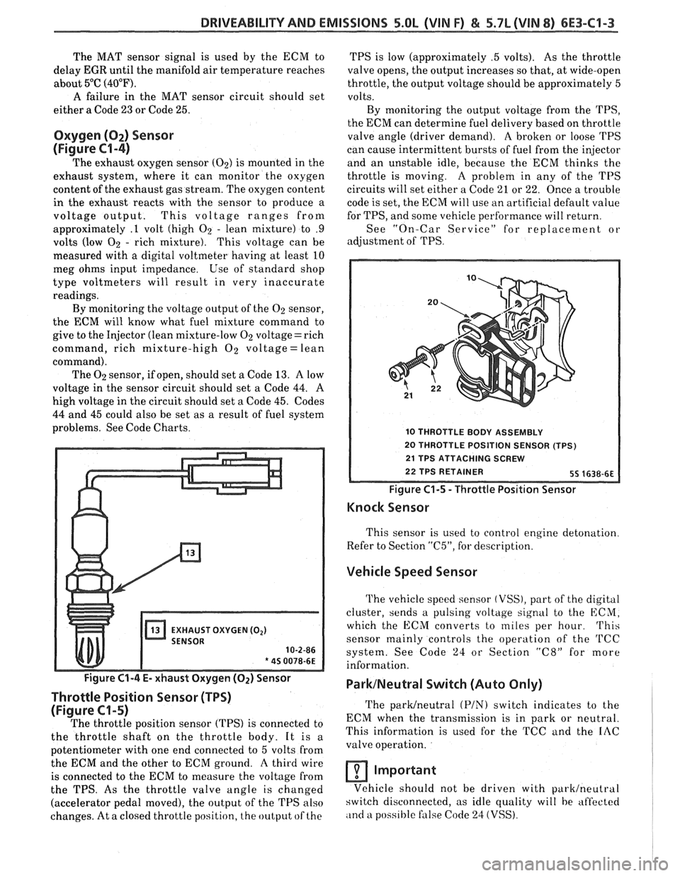
(Figure
€3-4)
The exhaust oxygen sensor (02) is mounted in the
exhaust system, where it can monitor the oxygen
content of the exhaust gas stream. The oxygen content
in the exhaust reacts with the sensor to produce a
voltage output. This voltage ranges from
approximately
.l volt (high 02 - lean mixture) to .9
volts (low 02 - rich mixture). This voltage can be
measured with a digital voltmeter having at least 10
meg ohms input impedance. Use of standard shop
type voltmeters will result in very inaccurate
readings.
By monitoring the voltage output of the 02 sensor,
the ECM will know what fuel mixture command to
give to the Injector (lean mixture-low
02 voltage= rich
command, rich mixture-high
O2 voltage = lean
command). The
02 sensor, if open, should set a Code 13. A low
voltage in the sensor circuit should set a Code
44. A
high voltage in the circuit should set a Code 45. Codes
44 and 45 could also be set as a result of fuel system
problems. See Code Charts.
EXHAUST OXYGEN (02)
10-2-86
* 45 0078-6E
Figure C1-4 E- xhaust Oxygen (Oz) Sensor
Throttle Position Sensor (TPS)
(Figure C1-5)
The throttle position sensor (TPS) is connected to
the throttle shaft on the throttle body. It is a
potentiometer with one end connected to
5 volts from
the ECM and the other to ECM ground.
A third wire
is connected to the ECM to measure the voltage from
the TPS. As the throttle valve angle is changed
(accelerator pedal moved), the output of the TPS also
changes. At a closed throttle position, the output of the TPS
is low (approximately
.5 volts). As the throttle
valve opens, the output increases so that, at wide-open
throttle, the output voltage should be approximately
5
volts.
By monitoring the output voltage from the
TPS,
the ECM can determine fuel delivery based on throttle
valve angle (driver demand).
A broken or loose 'I'PS
can cause intermittent bursts of fuel from the injector
and an unstable idle, because the ECM thinks the
throttle is moving.
A problem in any of the TPS
circuits will set either a Code
21 or 22. Once a trouble
code is set, the ECM will use an artificial default value
for TPS, and some vehicle perfhrmance will return.
See "On-Car Service" for replacement or
adjustment of
TPS.
10 THROTTLE BODY ASSEMBLY
20 THROTTLE POSITION SENSOR (TPS)
Figure
C1-5 - Throttle Position Sensor
Knock Sensor
This sensor is used to control engine detonation
Refer to Section
"C5", for description.
Vehicle Speed Sensor
The vehicle speed sensor (VSS), part of the digital
cluster, sends a pulsing voltage signal to the ECM,
which the ECM converts to miles per hour.
This
sensor mainly controls the operation of the 'I'CC
system. See Code 24 or Section "C8" for more
information.
ParklNeutral Switch (Auto Only)
The parWneutra1 (PIN) switch indicates to the
ECM when the transmission is in park or neutral.
This information is used for the TCC and the
IAC
valve operation.
Important
Vehicle should not be driven with parklneutral
switch disconnected, as idle quality will be aft'ected
,ind a poss~hle false Code 24 (VSS).
Page 885 of 1825
6E3-C1-10 5.OL (VIN F) & 5.7L (VIN 8) DRIVEABILITY AND EMISSIONS
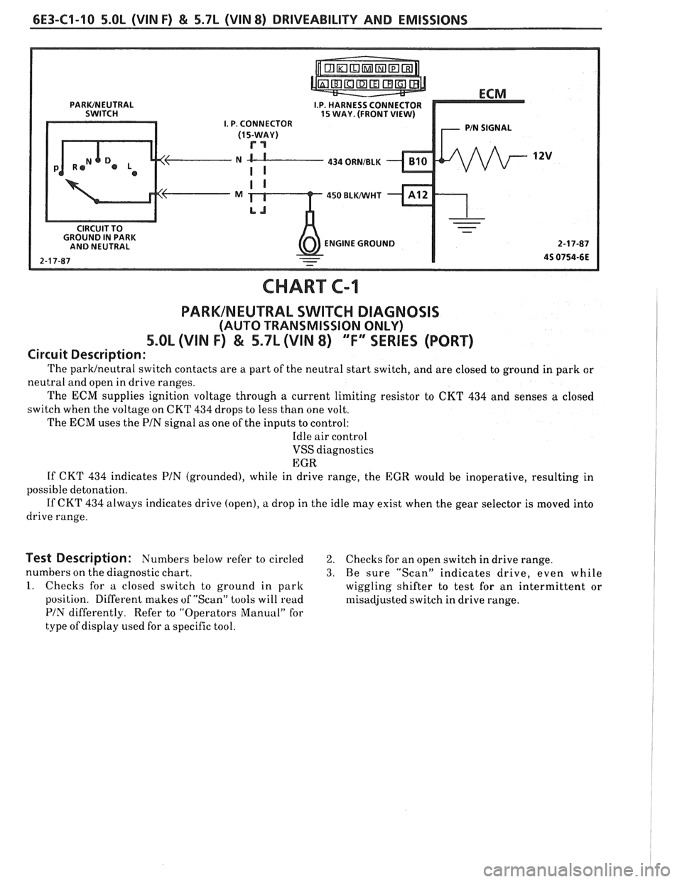
I.P. HARNESS CONNECTOR 15 WAY. (FRONT VIEW) I. P. CONNECTOR
N CL---- 434 ORNIBLK
450 BLWHT
ENGINE GROUND
CHART C-1
PARKINEUTRAL SWITCH DIAGNOSIS
(AUTO TRANSMISSION ONLY)
5.OL (VIN F) & 5.7L (VIN 8) "F" SERIES (PORT)
Circuit Description:
The parwneutral switch contacts are a part of the neutral start switch, and are closed to ground in park or
neutral and open in drive ranges.
The
ECM supplies ignition voltage through a current limiting resistor to CKT 434 and senses a closed
switch when the voltage on CKT
434 drops to less than one volt.
The ECM uses the PIN signal as one of the inputs to control:
Idle air control
VSS diagnostics
EGR
If CKT
434 indicates PIN (grounded), while in drive range, the EGR would be inoperative, resulting in
possible detonation.
If CKT 434 always indicates drive (open), a drop in the idle may exist when the gear selector is moved into
drive range.
Test Description: Numbers below refer to circled 2. Checks for an open switch in drive range.
numbers on the diagnostic chart.
3. Be sure "Scan" indicates drive, even while
1. Checks for a closed switch to ground in park
wiggling shifter to test for an intermittent or
position. Different makes of "Scan" tools will
read rllisadjusted switch in drive range.
PIN differently. Refer to "Operators Manual" for
type of display used for a specific tool.
Page 900 of 1825
DRIVEABILITY AND EMISSIONS 5.OL (VIN F) & 5.7b (VIN 8) 6E3-CZ-13
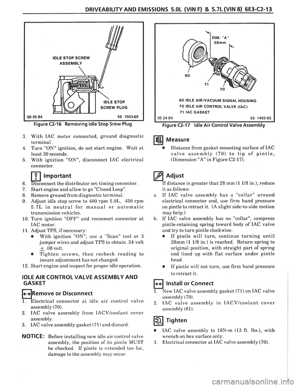
IDLE STOP SCREW
ASSEMBLY
IDLE STOP
SCREW PLUG
Figure C2-16 Removing Idle Stop Srew Plug
60 IDLE AIR/VACUUM SIGNAL HOUSING
70 IDLE AIR CONTROL VALVE (IAC)
71 IAC GASKET
Figure C2-17 Idle Air Control Valve Assembly
3. With IAC motor connected, ground diagnostic
terminal. Measure
4. Turn "ON" ignition, do not start engine. Wait at @ Distance from gasket mounting surface of IAC
least 30 seconds. valve assembly
(70) to tip of pintle,
5. With ignition
"ON", disconnect IAC electrical (Dimension
"A" in Figure C2-17).
connector.
Important
6. Disconnect
the distributor set-timing connector.
7. Start
engine and allow to go "Closed Loop".
8. Remove
ground from diagnostic terminal.
9. Adjust idle stop screw to 400 rpm 5.01,, 450 rpm
5.7L in neutral for manual or automatic
transmission vehicles.
10. Turn ignition "OFF" and reconnect connector at
IAC motor.
11. Adjust TPS, if necessary:
@ With ignition "ON", use a "Scan" tool or 3
jumper wires and adjust TPS to obtain .54 volt
+ .08 volt. - @ Tighten screws, then recheck reading to
insure adjustment has not changed.
12. Start engine and inspect for proper idle operation.
IDLE AIR CONTROL VALVE ASSEMBLY AND
CASKET
ORemove or Disconnect
1. Electrical connector at idle air control valve
assembly (70).
2. IAC valve assembly from IACVIcoolant cover
assembly.
3. IAC valve assembly gasket (71) and discard.
NOTICE: Before installing new idle air control valve
assembly, the position of its
pinlle MUST
be checked. If pintle is extended too far,
damage to the assembly
may occur
Adjust
If distance is greater that 28 mm (1 118 in.), reduce
it as follows:
a. If IAC valve assembly has a "collar" around
electrical connector end, use firm hand pressure
on pintle to retract it. (A slight side-to-side motion
may help.)
b. If
IAC valve assembly has no "collar", compress
pintle-retaining spring toward body of IAC valve
and try to turn pintle clockwise.
@ If pintle will turn, continue turning until
28mm
(1 118 in.) is reached. Return spring to
original position, with straight part of spring
end lined up with flat surface under pintle
head.
@ If pintle will not turn, use firm hand pressure
to retract it.
Install or Connect
1. New IAC valve assembly gasket (71) on IAC valve
assembly
(70).
2. IAC valve assembly in IACVIcoolant cover
assembly (61).
Tighten
IAC valve assembly to 18N.m (13 ft. Ibs.), with
wrench on hex surface only.
3. Electrical connector at IAC valve assembly (70).
Page 942 of 1825
DWlVEABlLlTV AND EMISSIONS 5.01, QVIN F) & 5.71 (VIN 8) 6E3-C8-1
TRANSMISSION CONVERTER CLUTCH (KC) SYSTEM
AND MANUAL "TRANSMISSION SHlFT LBGH"O"=Ob ONLY
CONTENTS
................ GENERAL DESCRIPTION C8-1 DIAGNOSIS ....................... .. C8-1
........ PURPOSE ......................... CS-1 SHIFT LIGHT (MIT) DESCRIPTION C8-1
....................... OPERATION C8-1 DIAGNOSIS ......................... CS-1
OM-CAR SERVICE ..................... C8-1
GENERAL DESCRIPTION
PURPOSE
The transmission converter clutch (TCC) system
uses
a solenoid operated valve in the automatic
transmission to couple the engine flywheel to the
output shaft of the transmission thru the torque
converter. This reduces the slippage losses in the
converter, which increases fuel economy.
OPERATION
For the converter clutch to apply, two conditions
must be met:
e Internal transmission fluid pressure must be
correct. For information on internal transmission
operation, see Section
"7A". This section will
cover only the electrical operation of the TCC
system.
@ The ECM grounds a switch internally to turn
"ON" a solenoid in the transmission. This moves a
check ball, which will allow the converter clutch
to apply, if the hydraulic pressure is correct, as
described above.
The ECM controls the TCC apply solenoid by
looking at several sensors:
@ Speedo Buffer Sensor (also called Vehicle Speed
Sensor
(VSS) Speed must be above a certain value
before the clutch can apply.
@ Coolant Temperature Sensor Engine must be
warmed
LIP before clutch can apply about 65" C
(149°F).
Throttle Position Sensor (TPS) After the
converter clutch applies, the ECM uses the
information
from the TPS to release the clutch
when the car is accelerating or decelerating at
a
certain rate.
The brake switch
is also part of the 'I'CC circuit as
it will remove battery voltage to the
'FCC solenoid
when the brake pedal is depressed.
@ Gear Select Switch The 4th gear switch is used to
send a signal to the ECM telling it when the
transmission is in 4th
gear
The ECM uses this information to vary the conditions
under which the clutch applies or releases. However,
the transmission does not have to be in fourth gear in
order for the ECM to turn the clutch "ON".
If the converter clutch is applied at all times, the
engine will stall immediately, just as in a manual
transmission with the clutch applied.
If the converter
clutch does not apply, fuel
ecomony may be lower than expected. If the vehicle
speed sensor fails, the TCC will not apply. If the 4th
gear switch does not operate, the TCC may not apply
at the right time.
DIAGNOSIS
The diagnosis of the TCC system is covered in
CHART C-$A. If the ECM detects a problem in the
system, a Code 24 should set. In this case, see Code 24
CHART.
SHIFT LIGHT (MR) DESCRIPTION
The purpose of the shift light is to provide a
display which indicates the optimum fuel economy
point for up shifting the manual transmission based
on engine speed and load. The display is
a lamp on the
instrument panel. Activation
of the ECM driver turns
the lamp "ON".
DIAGNOSIS
The shift light circuit can be checked using
CEIAR'I' C-8B.
ON-CAR SERVICE
See Section "8B" if the shift light bulb needs
replacement.
See Section
"GE" to repair wiring problem.
@ See Section "C- 1" if ECM is to be replaced.