1988 PONTIAC FIERO transmission
[x] Cancel search: transmissionPage 587 of 1825
6E2-C2-12 DRIVEABILITY AND EMISSIONS - 5.0b (VIN E)
3. Fuel meter body assembly.
4. Throttle body-to-fuel meter body gasket. Discard
gasket.
a Disassemble
@ TPS from old throttle body, according to previous
instructions, for reuse on new throttle body. (New
IAC valve comes with new throttle body.)
Assemble
@ TPS onto replacement throttle body assembly,
according to previous instructions.
Install or Connect
1. New throttle body-to-fuel meter body gasket.
2. Fuel meter body assembly on throttle body
assembly.
3. Fuel meter body-throttle
body attaching screw
assemblies that have been coated with locking
compound.
Tighten
@ Attaching screw assemblies to 4.0 N.m
(35.0 Ib. in.).
4. TBI
unit onto engine, as described below.
MllMiMhlM IDLE SPEED CHECK
The idle stop screw, used in mechanically setting
minimum engine idle speed has been set at the factory
and should not require further adjustment. However,
to check that the setting is correct, proceed as follows:
I. Plug any vacuum ports, as required.
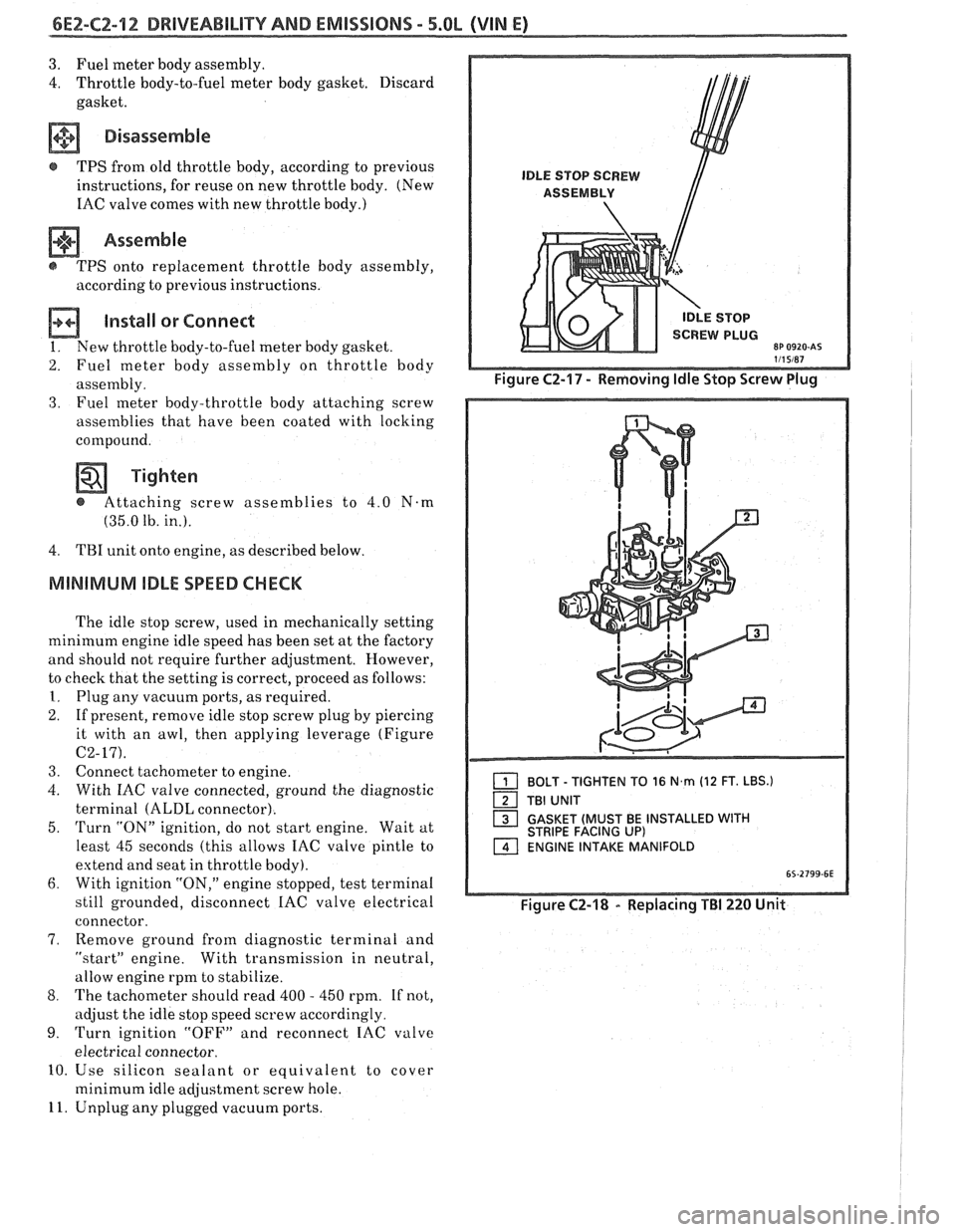
2. If present, remove idle stop screw plug by piercing
it with an awl, then applying leverage (Figure
C2-17).
3. Connect tachometer to engine.
4. With IAC valve connected, ground the diagnostic
terminal
(ALDL connector).
5.
Turn "ON" ignition, do not start engine. Wait at
least 45 seconds (this allows IAC valve pintle to
extend and seat in throttle body).
6. With ignition "ON," engine stopped, test terminal
still grounded, disconnect
IAC valve electrical
connector.
7, Remove ground from diagnostic terminal and
"startJ' engine. With transmission in neutral,
allow engine rpm to stabilize.
8. The tachometer should read 400 - 450 rpm. If not,
adjust the idle stop speed screw accordingly.
9. Turn ignition "OFF" and reconnect IAC valve
electrical connector.
10. Use silicon sealant or equivalent to cover
minimum idle adjustment screw hole.
11. Unplug any plugged vacuum ports.
1 BOLT - TIGHTEN TO 16 N,rn (12 FT. LBS.)
TBI UNIT
1 GASKET (MUST BE INSTALLED WITH STRIPE FACING UP) ENGINE INTAKE MANIFOLD
Figure C2-18 - Replacing TBI 220 Unit
Page 588 of 1825
DRIVEABILITY AND EMISSIONS - S.0L (VIN E) 6EZ-C2-13
"THROTTLE BODY INJECTION (TBI) UNIT
Replacement (Figure C2-18)
a Remove or Disconnect
1. THERMAC hose from engine fitting.
2. Electrical connectors to IAC valve, TPS and fuel
injectors.
3. Grommet with wires from throttle body.
4. Throttle linkage, return
spring(s) transmission
control cable and cruise control (wherever
applicable).
5. Vacuum hoses (noting position of hoses) and
bracket.
6. Fuel inlet and return lines (use back-up wrench
J-29698-A or BT-8251-A). Discard o-
rings from
nuts.
7. TBI mounting hardware.
8. TBI flange (manifold mounting) gasket and
discard.
NOTICE: Stuff manifold opening with a rag to
prevent material from entering
engine, and remove old gasket
material from surface of intake
manifold.
Inspect
@ Intake manifold bore for loose parts and foreign
material, etc.
@ Intake manifold sealing surface for cleanliness.
Install or Connect
1. New TBI flange (manifold mounting) gasket.
2.
TI31 with mounting hardware.
Tighten
@ Hardwareto, 16.5N-m( 12Ib. ft.).
3. New o-rings on fuel line nuts
4. Fuel inlet and outlet lines.
Tighten - @ To 23 N.m (17 lb. ft.). (Use back-up wrench
J-29698-A or BT-8251-A to keep TBI nuts
from turning.)
5. Vacuum hoses and bracket.
6. Throttle linkage, return
spring(s) transmission
control cable and cruise control (wherever
applicable).
7. Grommet with wire harness to throttle body.
8. Electrical connectors, making sure connectors are
fully seated and latched.
9. Check to see if accelerator pedal is free by
depressing pedal to the floor
and releasing while
engine is "OFF".
10. With engine "OFF," and ignition "ON," check for
leaks around fuel line nuts.
11. Start engine and check for fuel leaks.
FUEL HOSEIPIPE ASSEMBLIES
Materials
Fuel Lines. These are welded steel tubes, meeting GM
Specification 124-M, or its equivalent. The fuel feed
line is
318" diameter, and the fuel return line is 5/16"
diameter. Do not use copper or aluminum tubing to
replace steel tubing. Those materials do not have
satisfactory durability to withstand normal vehicle
vibr, ii t' lon.
Clamps. These are stainless steel, screw band type
clamps,
#249472, or equivalent.
Coupled Hose. These are not to be repaired and are
replaced
&as an assembly.
Uncoupled Hose. Use only reinforced fuel resistant
hose, made of "fluroelastomer" material.
[lo not use w
hose within 4 inches (100 mm) of any part of the
exhaust system, or within 10 inches
(254 mm) of the
catalytic converter. The hose's inside diameter nus st
match the outside diameter of the steel tubing.
Fuel Line Repair
1. Cut
a piece of fuel hose 4 inches (100 mm) longer
than the section of line to be removed. If
more
than 6 inches (152 tnm) is to be removed, use a .
combination of steel pipe and hose. The
hose
length should not be more than 10 inches total.
2. Cut a section of pipe to be replacccl, with a tube
cutter. C'se the first step of a double flaring tool to
form a bead on the ends
of the pipe and also, on the
new section of pipe, if used.
3. Slide
the hose
clanlps onto the pip2 and push the
hose
2 inches (51 mm) onto each portion of the fuel
pipe. Tighten a
clamp on each side of the repair.
4. Secure
fuel line to the frame.
FUEL PUMP RELAY
(Figure
CZ-19)
The fuel pump relay is mounted in the engine
compartment. Other than checking for loose
connectors, the only service possible is replacement.
OIL PRESSURE SWITCH
(Figure C2-20)
The oil pressure switch is li~ounted on the engine.
This switch is a parallel power supply, with the fuel
pump relay, and will provide battery voltage to the
fuel
pump, after approximately 28 kPa (4 psi) oil
pressure is reached.
Page 626 of 1825
DRIVEABILITY AND EMISSIONS - 5.0L (VIM E) 6E2-C8-1
SECTION C8
"FRANSMISSIBN CONVERnEW CLUTCH (TCC) SYSTEM
CONTENTS
GENERAL DESCRIPTION ............... C8-1 RESULTS OF INCORRECT TCC
PURPOSE
........................ C8-1 OPERATION ..................... C8-2
......................... OPERATION ...................... C8-1 DIAGNOSIS CS-2
.................... CIRCUIT DESCRIPTION ....e.e..eea..e C8-1 ON-CAR SERVICE C8-2
................. PARTS INFORMATION C8-2
GENERAL DESCRIPTION
PURPOSE
The transmission converter clutch (TCC) system
is designed to eliminate power loss by the converter
(slippage) thus increasing fuel economy. By locking
the converter clutch,
a more effective coupling to the
flywheel is achieved. The converter clutch is operated
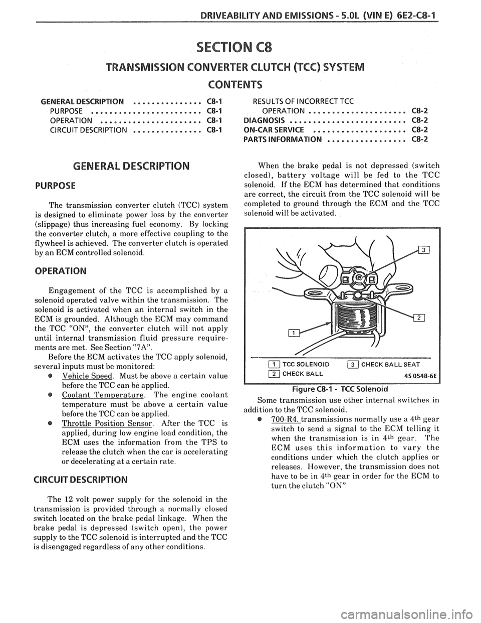
by an ECM controlled solenoid.
OPERATION
Engagement of the TCC is accomplished by a
solenoid operated valve within the transmission. The
solenoid is activated when an internal switch in the
ECM is grounded. Although the ECM may command
the TCC
"ON", the converter clutch will not apply
until internal transmission fluid pressure require-
ments are met. See Section
"7A".
Before the ECM activates the TCC apply solenoid,
several inputs must be monitored:
e Vehicle Speed. Must be above a certain value
before the TCC can be applied.
Coolant Temperature. The engine coolant
temperature must be above a certain value
before the TCC can be applied.
@ Throttle Position Sensor. After the TCC is
applied, during low engine load condition, the
ECM uses the information from the TPS to
release the clutch when the car is accelerating
or decelerating at a certain rate.
CIRCUIT DESCRIPTION
When the brake pedal is not depressed (switch
closed), battery voltage will be fed to the TCC
solenoid. If the ECM has determined that conditions
are correct, the circuit from the TCC solenoid will be
completed to ground through the ECM and the TCC
solenoid will be activated.
Figure C8-1 - TCC Solenoid
Some transmission use other internal switches in
addition to the TCC solenoid.
@ 700-R4. transmissions normally use a 4th gear
switch to send
a signal to the ECM telling it
when the transmission is in
4th gear. The
ECM uses this information to vary the
conditions under which the clutch applies or
releases. However, the transmission does not
have to be in
4th gear in order for the ECM to
turn the clutch
"ON"
The 12 volt power supply for the solenoid in the
transmission is provided through
a normally closed
switch located on the brake pedal linkage. When the
brake pedal is depressed (switch open), the power
supply to the TCC solenoid is interrupted and the TCC
is disengaged regardless of any other conditions.
Page 627 of 1825
6Ef-C8-2 BRlVEABlLlYV AND EMISSIONS - 5.OL (VIN E) ----
RESULTS OF INCORRECTTCC OPERATION
An engine stall will result if the converter clutch
remains applied at all times.
If the converter clutch does not apply, fuel
economy may be lower than expected.
The transmission converter clutch
(TCC) system
has different operating characteristics than an
automatic transmission without TCC.
If the driver
complains of a "chuggle" or "surge" condition, the car
should be road tested and compared to a similar car to
see if a real problem exists. Another TCC complaint
may be
a downshift felt when going up a grade,
especially with cruise control. This may not be
a
downshift, but a clutch disengagement due to the
change in TPS to maintain cruising speed. The
Owner's Manual section on TCC operation should be
reviewed with the driver.
DIAGNOSIS
The diagnosis of the TCC system is covered in
ClIART C-8. If the ECM detects a problem in the VSS
system, a Code
24 should set. In this case see Code 24
Chart.
If the ECM doesn't switch the TCC "ON" when
driving, but will turn it
"ON" when the "test"
terminal is grounded with ignition "ON" and engine
stopped, the sensors such as coolant, speed, and
throttle position should be checked.
ON-CAW SERVICE
@ See Section "7" for TCC Solenoid.
@ See Section "SH" for VSS (HP mounted) and brake
system.
PAR- SNFORMATBIQN
PART NAME GRQUQ
.......................... Sensor, VSS 9.761
........................ Solenoid, TCC 4.122
Page 629 of 1825

6EZ-C8-4 DRIVEABILITY AND EMISSIONS - 5.OL (VIN E)
I5 WAY (FRONT VIEW)
SPEED INPUT
4rH GEAR SIGNAL
422 TANIBLK
ALDL CONNECTOR
CHART C-8A
TRANSMISSION CONVERTER CLUTCH (TCC)
ELECTRICAL DIAGNOSIS
(Page 1 of 2)
5.OL (VIN E) "F" "SERIES (TBI)
Circuit Description:
The purpose of the automatic transmission torque converter clutch is to eliminate the power loss of the
torque converter, when the vehicle is in a cruise condition. This allows the convenience of the automatic
transmission and the fuel economy of a manual transmission.
Fused battery ignition is supplied to the TCC solenoid through the brake switch. the ECM will engage
TCC
by grounding CKT 422 to energize the solenoid.
TCC will engage when:
- Vehicle speed above 24 mph - Engine at normal operating temperature (above 70°C, 156°F)
- Throttle position sensor output not changing, indicating a steady road speed
- Brake switch closed
Test Description: Numbers below refer to circled solenoids
and relays before installing a
numbers on the diagnostic chart. replacement ECM. Replace
any solenoid or relay
1. Confirms 12 volt supply as well as continuity of that
measures less than 20 ohms.
TCC circuit.
2. Grounding the diagnostic terminal with engine Diagnostic Aids:
"OFF", should energize the capability of the ECM An
engine coolant thermostat that is stuck open or
to control the solenoid. opens
at too low a temperature, may result in an
3. Solenoid coil resistance must measure more than inoperative TCC.
20 ohms. Less resistance will cause early failure
of the ECM
drive^.". Using an ohmmeter, check
the solenoid coil resistance of
all ECM controlled
Page 631 of 1825
6E2-C8-6 DRIVEABILITY AND EMISSIONS - 5.OL (VIN E)
I.P. HARNESS CONNECTOR 15 WAY (FRONT VIEW)
ECM
VEHICLE SPEED SIGNAL
SPEED INPUT
4TH GEAR SIGNAL
422 TANIBLK
ALDL CONNECTOR
* 85 4435-66 6-8-87
CHART C-8A
700-4R TRANSMISSION
ELECTRICAL DIAGNOSIS
(Page 2 of 2)
5.0L (VIN E) "F" "SERIES (TBI)
Circuit Description:
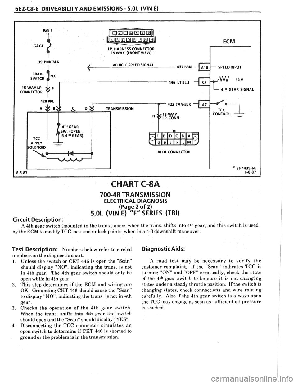
A 4th gear switch (mounted in the trans.) opens when the trans. shifts into 4th gear, and this switch is used
by the ECM to modify TCC lock and unlock points, when in a 4-3 downshift maneuver.
Test Description: Numbers below refer to circled
numbers on the diagnostic chart.
1. Unless the switch or CKT 446 is open the "Scan"
should display "NO", indicating the trans. is not
in 4th gear.
The 4th gear switch should only he
open whiie in 4th gear.
2. This step determines if the ECM and wiring are
OK. Grounding CKT 446 should cause the "Scan"
to display "NO", indicating the trans. is not in 4th
gear.
3. Checks the operation of the 4th gear switch.
When the trans. shifts into 4th
geir the switch
should open and the "Scan" should display
"YES".
4. Disconnecting the TCC connector simulates an
open switch to determine if CKT
446 is shorted to
ground or the problem is in the transmission.
Diagnostic Aids:
A road test may be necessary to verify the
customer complaint. If the "Scan" indicates TCC is
turning
"ON" and "OFF" erratically, check the state
of the 4th gear switch to he sure it is not changing
states under a steady throttle position.
If the switch is
changing states, check connections and wire routing
carefully. Also if the 4th gear switch is always open
the
TCC may engage as soon as sufficient oil pressure
is reached.
Page 633 of 1825
6E2-C8-8 DRIVEABILITY AND EMISSIONS - 5.OL (VIN E)
I.P. HARNESS CONNECTOR
INTRUMENT 15 WAY. (FRONT VIEW)
CHART C-8B
MANUAL "TRANSMISSION (Mn)
SWIFT LIGHXCHCK
5.OL (VIN E) "F" "SERIES ("Ti)
Circuit Description:
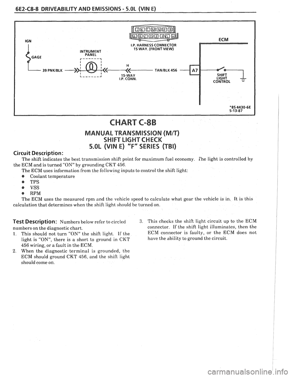
The shift indicates the best transmission shift point for maximum fuel economy. Phe light is controlled by
the ECM and is turned "ON" by grounding
CKT 456.
The ECM uses information from the following inputs to control the shift light:
@ Coolant temperature
@ TPS
VSS
@ RPM
The ECM uses the measured rpm and the vehicle speed to calculate what gear the vehicle is in. It is this
calculation that determines when the shift light should be
turned on.
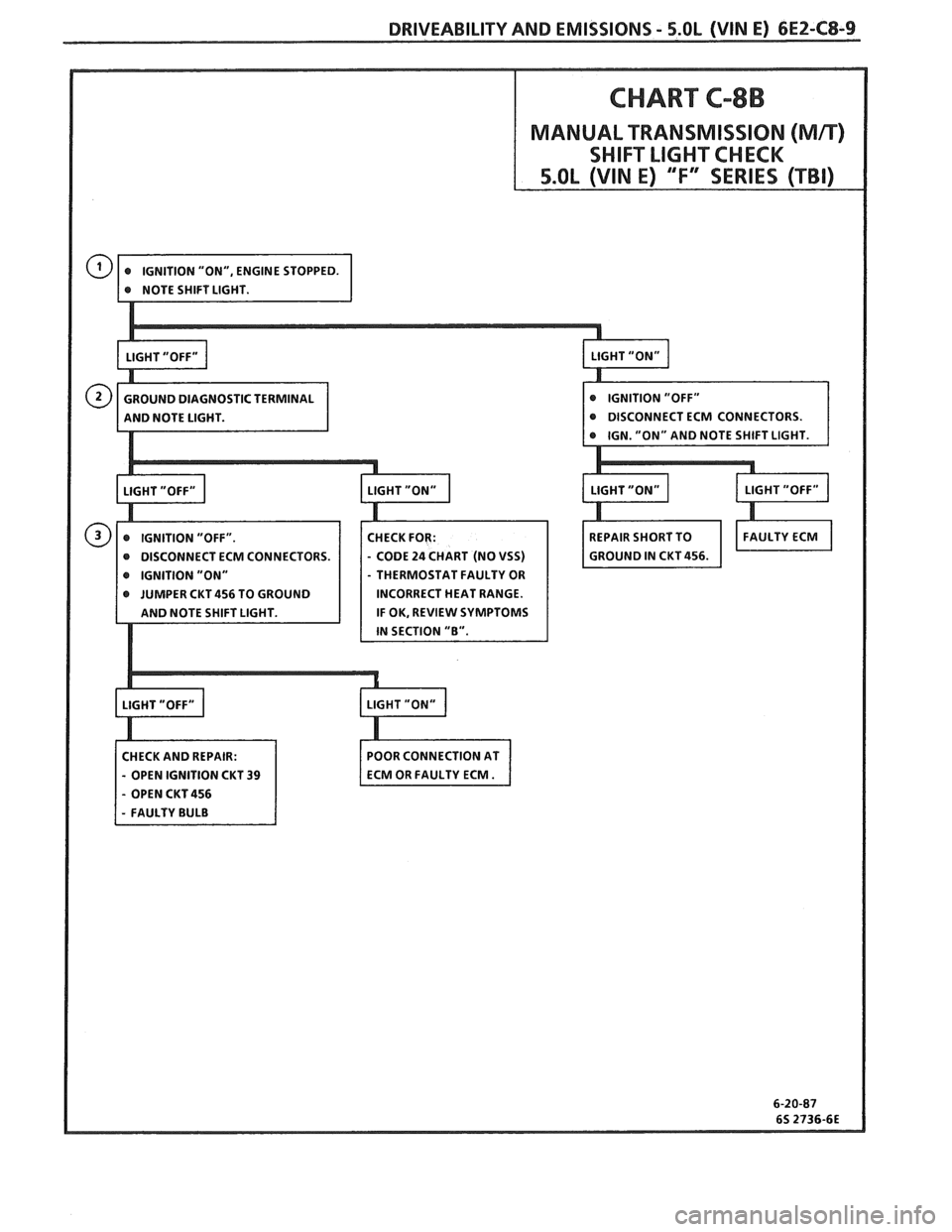
Test Description: Numbers below refer to circled 3. This checks the shift light circuit up to the ECM
numbers on the diagnostic chart. connector.
If the shift light illuminates, then the
1. This should not turn "ON" the shift light. If the ECM
connector is faulty, or the ECM does not
light is "ON", there is
a short to ground in CKT have the ability to ground the circuit.
456 wiring, or a fault in the ECM.
2. When the diagnostic terminal is grounded, the
ECM should ground CKT 456, and the shift light
should come on.
Page 634 of 1825
DRIVEABILITY AND EMISSIONS - S.OL (WIN E) 6EZ-CS-9
CHART C-8B
MANUAL TRANSMISSION (Mn)
SHIFT LIGHT CHECK
CM CONNECTORS.
IGNITION "ON" THERMOSTAT FAULTY OR
JUMPER CKT 456 TO GROUND INCORRECT HEAT RANGE.
IF OK, REVIEW SYMPTOMS
CHECK AND REPAIR:
- OPEN IGNITION CKT 39
- OPEN CKT 456