1988 PONTIAC FIERO transmission
[x] Cancel search: transmissionPage 222 of 1825
REAR SUSPENSION 30.1
SECTION 3D
REAR SUSPENS
NOTICE: All rear suspension fasteners are important attaching parts in that they could affect the
performance of vital parts and systems, and/or could result in major repair expense. They must be replaced with
one of the same part number or with an equivalent part if replacement becomes necessary. Do not use
a
replacement part of lesser quality or substitute design. Torque values must be used as specified during reassembly
to assure proper retention of all parts. There is to be no welding as it may result in extensive damage and weakening
of the metal.
CONTENTS
General Information ................................ 3D- 1 Rear Lower Control Arm ............................ 3D-4
Qn-Car Service ............................ .. .......... 3D- 1 Bushing (Rear Lower Control Arm) ........... 3D-4
Shock Absorbers ........................................ 3D- 1 Torque Arm .............................................. 3D-5
Coil Springs and Insulators ......................... 3D- 1 Rear Stabilizer Shaft .................................. 3D-6
Track Bar ................................................... 3D-3 Bumper (Rubber) ....................................... 3D-6
Track Bar Brace ................... .. ................. 3D-3 Torque Specifications .................................. 3D-9
GENERAL INFORMATION
The rear axle assembly is attached to the vehicle
through a link type suspension system. The axle
housing is connected to the body by two lower control
arms and a track bar. A single torque arm is used in
place of upper control arms. It is rigidly mounted to the
rear axle housing at the rear and through a rubber
bushing to the transmission at the front. Coil springs
are used to support the weight of the car, and ride
control is provided by shock absorbers mounted to the
rear of the axle housing. A stabilizer shaft is optional.
The shock absorbers are mounted at the bottom
with a bolt and nut to brackets welded to the axle
housing, and at the top to the reinforced body area with
a nut. The only service the shock absorbers require is
replacement if they
have lost tllcir resistance, are
danaged, or are leaking flldd.
ON-CAR SERVICE
SI-IOCK ABSORBERS
Fig. 602
Remove or Disconnect
1. Hoist car and support rear axle.
2. From above, pull back carpeting and remove
shock absorber upper mounting nut.
NOTICE: Axle assembly must be supported
before removing upper shock absorber nut to avoid
possible damage to brake lines, track bar and prop
shaft.
3. Loosen and remove shock absorber lower
mounting nut from shock absorber. Remove
shock.
Install or Connect
NOTICE: See NOTICE on Page 3D-1 of this
section.
1. Position shock absorber through body mounting
hole and loosely install the lower shock absorber
mounting nut.
2. From above, install the upper shock absorber
retainer and nut. Torque nut.
3. Torque lower shock absorber nut.
4. Remove rear axle support and lower car.
COIL SPRINGS AND INSULATORS
Fig. 603
Remove or Disconnect
1. Hoist car on non twin post-type hoist and support
rear axle assembly with an adjustable lifting
device.
2. Track bar mounting bolt at axle assembly.
Loosen track bar bolt at body brace.
3. Rear brake hose clip at underbody to allow
additional axle drop.
4. Right and left shock absorber lower attaching
nuts.
5. Carefully lower rear axle and remove spring(s)
and or insulator(s).
NOTICE: DO NOT suspend rear axle by brake
hose. Damage to hose could result.
Install or Connect
NOTICE: See NOTICE on Page 3D-1 of this
section.
Page 227 of 1825
30-8 WEAR SUSPENSION
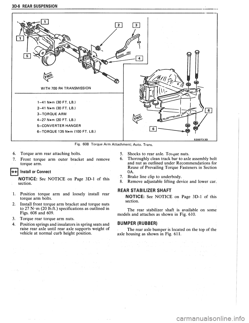
WITH 700 R4 TRANSMISSION
1-41 Nern (30 FT.
LB.)
2-41 Nern (30 FT. LB.)
3-TORQUE ARM
4-27 Nern
(20 FT. LB.)
5-CONVERTER HANGER
6-TORQUE 135
Nern (100 FT. LB.)
Fig. 608 Torque Arm Attachment; Auto. Trans.
6. Torque arm rear attaching bolts. 5. Shocks to rear axle. Toique nuts.
7. Front torque arm outer bracket and remove
6. Thoroughly clean track bar to axle assembly bolt
torque arm. and nut
as outlined under Recommendations for
Reuse of Prevailing Torque Fasteners in Section
Install or Connect OA.
7. Brake line clip to underbody. On Page 3D-1 of this 8. Remove adjustable lifting device and lower car.
section.
1. Position torque arm and loosely install rear
torque arm bolts.
2. Install front torque arm bracket and torque nuts
to 27
N.m (20 1b.ft.) specifications as outlined in
Figs.
608 and 609.
3.
Torque rear torque arm nuts.
4. Position springs and insulators in spring seats and
raise rear axle until rear axle supports weight of
vehicle at normal curb height position.
REAR STABILIZER SHAFT
NOTICE: See NOTICE on Page 3D-1 of this
section.
The rear stabilizer shaft is available on some
models and attaches as shown in Fig.
610.
BUMPER (RUBBER)
The rear axle bumper is located on the top of the
axle housing as shown in Fig.
61 1.
Page 228 of 1825
REAR SUSPENSION 3D-7
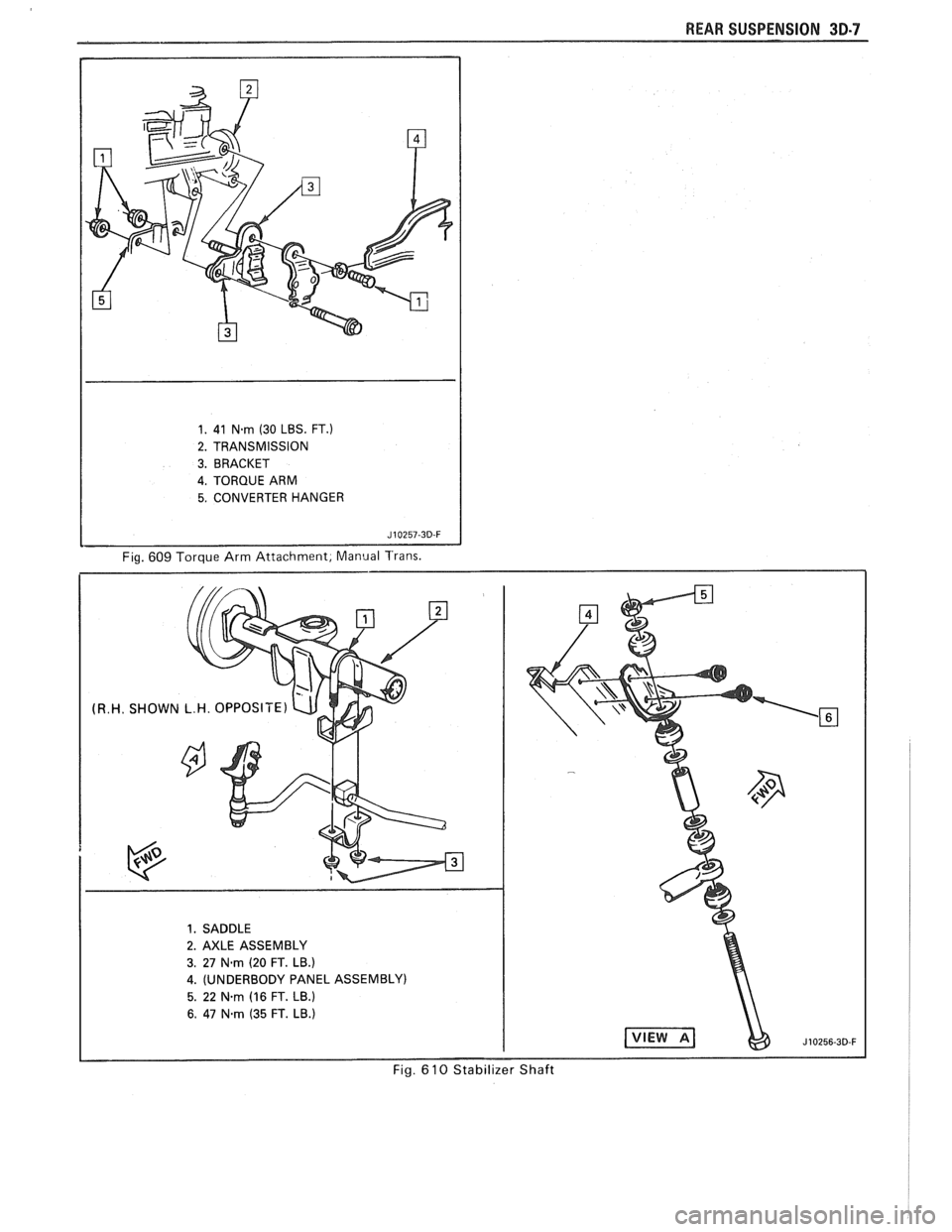
1. 41 N-rn (30 LBS. FT.)
2. TRANSMISSION
3. BRACKET
4. TORQUE ARM
5. CONVERTER HANGER
Fig. 609 Torque Arm Attachment, Manual Trans.
Page 239 of 1825
3E-8 TIRES AND WHEELS
nearest the valve stem, and a 1/2 ounce balance weight
should be added 180" opposite the locking nut on the
wheel's inboard side.
When rotating tires, always re-install the locking
nut nearest the tire valve stem so that it remains
opposite the 1/2 ounce balance weight. This procedure
will improve the on-car wheel balance by compensating
for the heavy locking wheel nut.
Off-Car Balancing
Most electronic off-car balancers are more
accurate than the on-car spin balancers. They are easy
to use and give a dynamic (two plane) balance.
Although they do not correct for drum or rotor
unbalance as does on-car spin balancing, this is
overcome by their accuracy (usually to within 1/8
ounce). When balancing off-car, the wheel should
locate on the balancer with a cone through the back
side of the center pilot hole (not by the wheel stud
holes).
On-Car Balancing
When needed, on-car balancing will help correct
vibrations due to brake drum, rotor, and wheel cover
imbalance.
When balancing on car, do not remove the
balance weights from the off-car dynamic balance. If
more than one ounce of additional weight is required,
it should be split between the inner and outer rim
flange.
NOTICE: The driven tire and wheel assemblies
should be spun using the engine. Limit speed as
stated in the following Caution.
CAUTION: Do not spin the drive
wheels faster than
35 mph (55 km/h)
as indicated by the speedometer. This
limit is necessary because the
speedometer indicates only one-half
of the actual wheel speed when one
drive wheel is spinning and the other
drive wheel is stopped. Personal injury
and damage may result from high
speed spinning.
CAUTION: On cars equipped with
limited slip rear axles, do not attempt
to balance a tire on a
drive wheel with
the other drive wheel on the ground.
The car may drive through this wheel
and cause the car to move
unexpectedly, resulting in personal
injury and property damage.
To distinguish between standard rear axle and
limited slip, raise rear of car so both tires are clear of
ground. With the transmission in park (in gear with
manual transmission), attempt to turn one wheel by
hand. If the wheel can be turned, it is a standard rear
axle; if the wheel cannot be turned, it is a limited slip
rear axle. Also, check for Limited Slip
(G80) on Service
Parts Identification label.
Wheel Weights
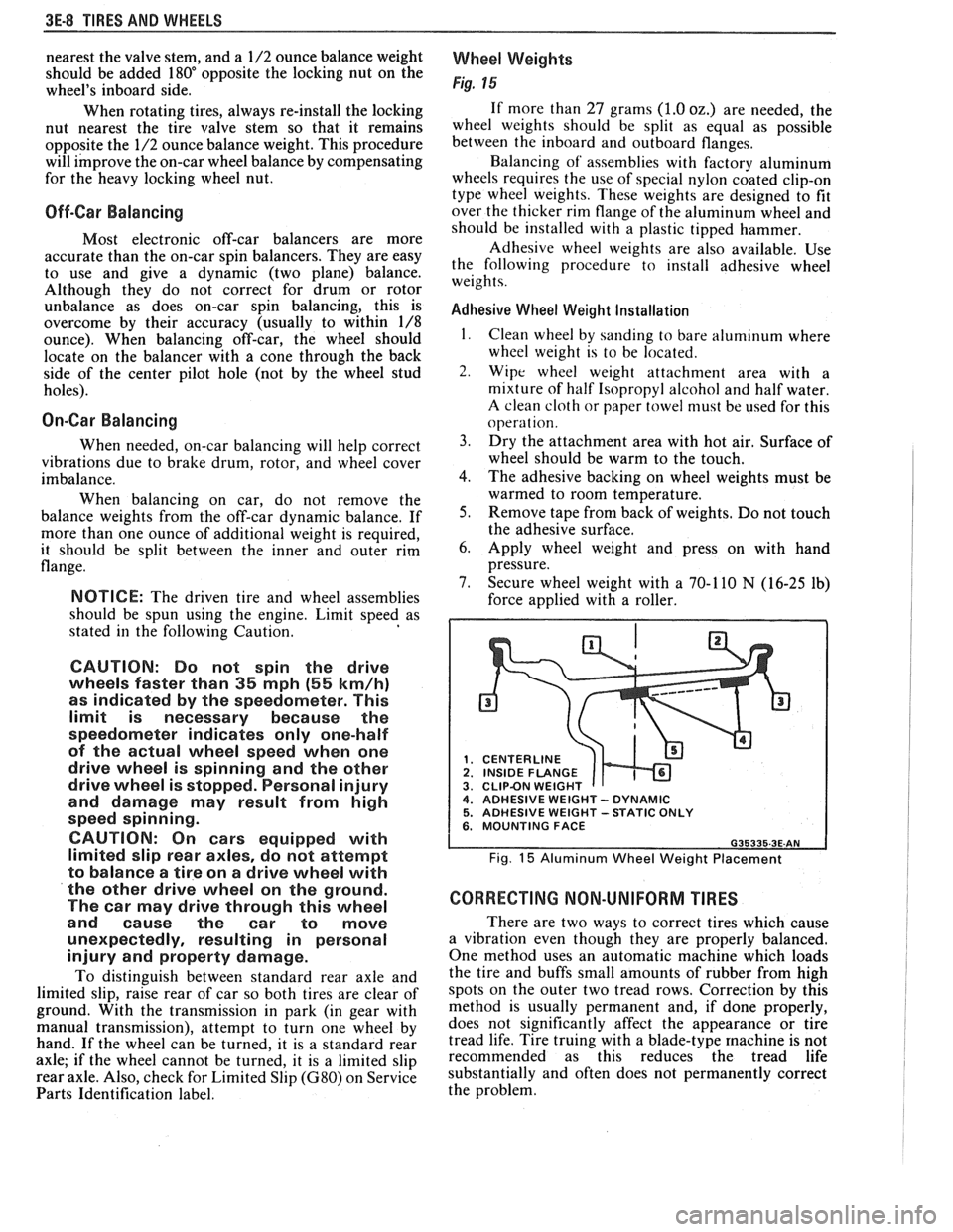
Fig. 15
If more than 27 grams (1.0 oz.) are needed, the
wheel weights should be split as equal as possible
between the inboard and outboard flanges.
Balancing of' assemblies with factory aluminum
wheels requires the use of special nylon coated clip-on
type wheel weights. These weights are designed to fit
over the thicker rim flange of the aluminum wheel and
should be installed with a plastic tipped hammer.
Adhesive wheel weights are also available. Use
the following procedure to install adhesive wheel
weights.
Adhesive Wheel Weight Installation
1. Clean wheel by sanding to bare aluminum where
wheel weight is to be located.
2. Wipe wheel weight attachment area with a
mixture of half Isopropyl alcohol and half water.
A clean cloth or paper towel niust be used for this
operat ion.
3. Dry the attachment area with hot air. Surface of
wheel should be warm to the touch.
4. The adhesive backing on wheel weights must be
warmed to room temperature.
5. Remove tape from back of weights. Do not touch
the adhesive surface.
6. Apply wheel weight and press on with hand
pressure.
7. Secure wheel weight with a 70-1 10
N (16-25 lb)
force applied with a roller.
CENTERLINE
1 INSIDE FLANGE CLIPBN WEIGHT 4. ADHESIVE WEIGHT - DYNAMIC 5. ADHESIVE WEIGHT -STATIC ONLY 6. MOUNTING FACE
Fig. 15 Aluminum Wheel Weight Placement
CORRECTING NON-UNIFORM TIRES
There are two ways to correct tires which cause
a vibration even though they are properly balanced.
One method uses an automatic machine which loads
the tire and buffs small amounts of rubber from high
spots on the outer two tread rows. Correction by this
method is usually permanent and, if done properly,
does not significantly affect the appearance or tire
tread life. Tire truing with a blade-type
machine is not
recommended as this reduces the tread life
substantially and often does not permanently correct
the problem.
Page 242 of 1825
PROPELLER SHAFT 4A-1
PROPELLER SHAFT
NOTICE: The propeller shaft to pinion flange or slip yoke fasteners are important attaching parts in that
they may affect the performance of vital components and systems, which may result in a major repair expense.
They must be replaced with one of the same part number or with an equivalent part, if replacement becomes
necessary. Do not use a replacement part of lesser quality or substitute design. Torque values must be used as
specified during reassembly to assure proper retention of these parts.
CONTENTS
GENERAL DESCRIPTION ........................ 4A-1
DIAGNOSIS ......................... ............ 4A-1
ON-VEHICLE SERVICE ........................... 4A-I
Propeller Shaft Run-Out
....................................... Measurement 4A- 1
Companion Flange Run-Out
Measurement
............................................. 4A-2
........... Universal Joint Angle Measurement 4A-3
............................ Propeller Shaft Balancing 4A-4
.............................................. Propeller Shaft 4A-8
Removal
.................... .. ............................. 4A-8
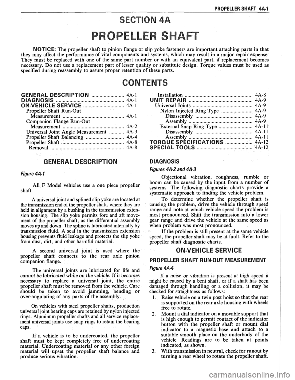
GENERAL DESCRIPTION
Figure 4A- I
.............................................. Installation 4A-8
UNIT REPAIR ............................................... 4A-9
Universal Joints
...................... ... ............ 4A-9
....................... Nylon Injected Ring Type 4A-9
..... ....................... Disassembly .... 4A-9
.......................................... Assembly 4A-9
......................... External Snap Ring Type 4A- l 1
............. .................... Disassembly .. 4A- 1 1
........................................... Assembly
4A- 1 1
.................... TORQUE SPECIFICATIONS 4A-12
.................................. SPECIAL TOOLS 4A-12
DIAGNOSIS
Figures 4A-2 and 4A-3
Obiectional vibration, roughness, rumble or
boom
can be caused by the input from a number of
shaft. use a One piece propeller systems. The following diagnostic charts provide a
systematic approach to finding the vehicle problem.
A universal joint and splined slip yoke are located at
the transmission end of the propeller shaft, where they are
held in alignment by a bushing in the transmission exten-
sion housing. The slip yoke permits fore and aft move-
ment of the propeller shaft, as the differential assembly
moves up and down. The spline is lubricated internally by
transmission fluid. A seal in the transmission extension
housing prevents fluid leakage and protects the slip yoke
from dust,
dirt, and other harmful material.
A second universal joint is used where the
propeller shaft connects to the rear axle pinion
companion flange.
The universal joints are lubricated for life and
cannot be lubricated while on the vehicle.
If it becomes
necessary to replace a universal joint, the entire
propeller shaft must be removed from the vehicle. Care
should be taken to avoid jamming, bending or
over-angulating of any parts of the assembly.
On vehicles with steel propeller shafts, production
universal joint bearing caps are retained by nylon injected
rings. Aluminum propeller shafts and all service replace-
ment universal joints use snap rings to retain the bearing
caps.
If a vehicle is to be undercoated, the propeller
shaft must be kept completely free of undercoating
material. Undercoating material or any other foreign
material will upset the propeller shaft balance and
produce serious vibration. To
determine whether the propeller shaft is
causing the problem, drive the vehicle through speed
range and note at which vehicle speed the problem is
most pronounced. Shift the transmission into a lower
gear range and drive the vehicle at the same speed as
when problem was most pronounced.
If the problem is still present at the same vehicle
speed, the propeller shaft may be at fault. Refer to the
propeller shaft diagnostic charts.
ON-VEHICLE SERVICE
PROPELLER SHAFT RUN-OUT MEASUREMENT
Figure 4A-4
If a noise or vibration is present at high speed it
might be caused by a bent shaft, or if a shaft has been
damaged through handling or a collision, it may be
checked for straightness as follows:
1. Raise vehicle on a twin post hoist so that the rear
is supported on the rear axle housing with wheels
free to rotate.
2. Mount
a dial indicator on a movable support that
is high enough to permit contact of the indicator
button with the propeller shaft or mount dial
indicator to a magnetic base and attach to a
suitable smooth place on the underbody of the
vehicle. Readings are to be taken at points
indicated, as shown.
3. With transmission in neutral, check for runout by
turning a rear wheel to rotate the propeller shaft.
Page 243 of 1825
4A-2 PROPELLER SHAFT
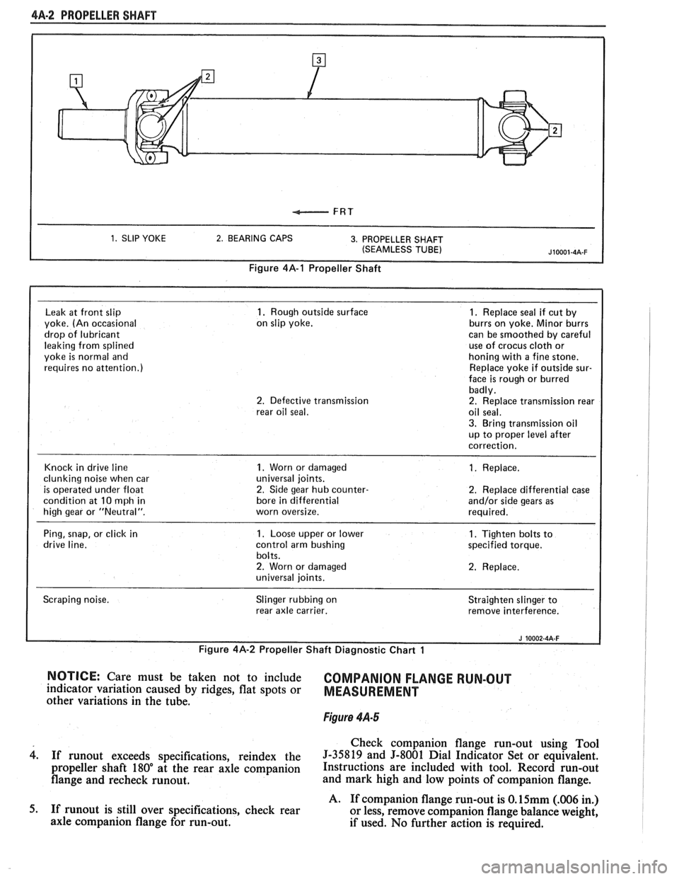
1. SLIP YOKE 2. BEARING CAPS 3. PROPELLER SHAFT
(SEAMLESS TUBE)
Figure 4A-1 Propeller Shaft
Leak
at front slip 1. Rough outside surface 1. Replace seal if cut by
yoke. (An occasional on
slip yoke. burrs on yoke.
Minor burrs
drop of lubricant can
be smoothed by careful
leaking from splined use
of crocus
cloth or
yoke
is normal and honing
with a fine stone.
requires no attention.) Replace
yoke if outside sur-
face is rough or burred
badly.
2. Defective transmission 2. Replace transmission rear
rear oil seal. oil seal.
3. Bring transmission oil
up to proper level after
correction.
Knock in drive line
1. Worn or damaged 1. Replace.
clunking noise when car universal
joints.
is operated under float 2. Side gear hub counter- 2. Replace differential case
condition at
10 mph in bore
in differential and/or side gears as
high gear or "Neutral". worn oversize. required.
Ping, snap, or click in
1. Loose upper or lower 1. Tighten bolts to
drive line. control arm bushing specified torque.
bolts.
2. Worn or damaged 2. Replace.
universal joints.
Scraping noise. Slinger
rubbing on
rear axle carrier. Straighten
slinger to
remove interference.
I
Figure 4A-2 Propeller Shaft Diagnostic Chart 1 I i
NOTICE: Care must be taken not to include COMPANION FLANGE RUN-OUT indicator variation caused by ridges, flat spots or MEASUREMENT other variations in the tube.
Figure 4.4-5
Check companion flange run-out using Tool
4. If runout exceeds specifications, reindex the 5-35819 and 5-8001 Dial Indicator Set or equivalent.
propeller shaft 180" at the rear axle companion Instructions are included with tool. Record run-out
flange and recheck runout. and mark high and low points of companion flange.
A. If companion flange run-out is
O.15mm (.006 in.)
5. If
runout is still over specifications, check rear
or less, remove companion flange balance weight,
axle companion flange for run-out.
if used. No further action is required.
Page 244 of 1825
PROPELLER SHAFT $A-3
B. If companion flange run-out is over 0.15mm (.006
in.) but less than 0.28mm (.011 in.) and balance
weight is at or near low point of companion flange
run-out, no further action is required.
If balance weight is not at or near low point of
companion flange run-out, remove weight.
6. If companion flange run-out is over 0.28mm (.011
in.), but no greater than 0.38mm (.015 in.) and
balance weight is at or near low point of
companion flange run-out, no further action is
required.
If balance weight is not at or near low point of
companion flange
runout, remove weight and
reindex companion flange until run-out is 0.25
mm
(.010 in.) or less.
If impossible to achieve
0.25mm (.010 in.) or less
run-out, install a new companion flange and
recheck for
0.25mm (.010 in.) or less run-out.
Service replacement companion flanges are not
equipped with balance weights and no weights
should be added.
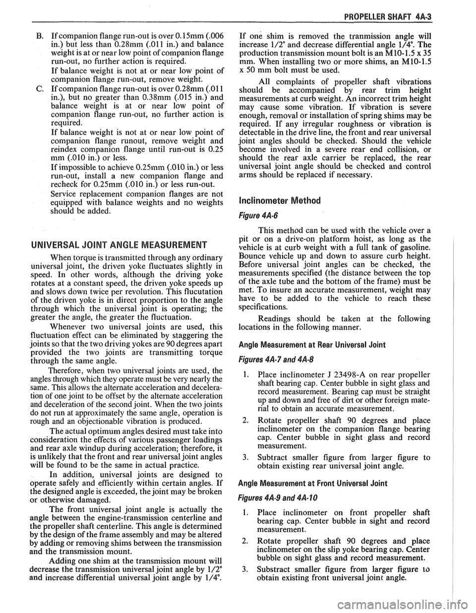
UNIVERSAL JOINT ANGLE MEASUREMENT
When torque is transmitted through any ordinary
universal joint, the driven yoke fluctuates slightly in
speed. In other words, although the driving yoke
rotates at a constant speed, the driven yoke speeds up
and slows down twice per revolution. This flucutation
of the driven yoke is in direct proportion to the angle
through which the universal joint is operating; the
greater the angle, the greater the fluctuation.
Whenever two universal joints are used, this
fluctuation effect can be eliminated by staggering the
joints so that the two driving yokes are 90 degrees apart
provided the two joints are transmitting torque
through the same angle.
Therefore, when two universal joints are used, the
angles through which they operate must be very nearly the
same. This allows the alternate acceleration and decelera-
tion of one joint to be offset by the alternate acceleration
and deceleration of the second joint. When the two joints
do not run at approximately the same angle, operation is
rough and an objectionable vibration is produced.
The actual optimum angles desired must take into
consideration the effects of various passenger loadings
and rear axle windup during acceleration; therefore, it
is unlikely that the front and rear universal joint angles
will be found to be the same in actual practice.
In addition, universal joints are designed to
operate safely and efficiently within certain angles. If
the designed angle is exceeded, the joint may be broken
or otherwise damaged.
The front universal joint angle is actually the
angle between the engine-transmission centerline and
the propeller shaft centerline. This angle is determined
by the design of the frame assembly and may be altered
by adding or removing shims between the transmission
and the transmission mount.
Adding one shim at the transmission mount will
decrease the transmission universal joint angle by
1/2"
and increase differential universal joint angle by 1/4".
If one shim is removed the tranmission angle will
increase
1/2" and decrease differential angle I/@. The
production transmission mount bolt is an
M10-1.5 x 35
mm. When installing two or more shims, an
M10-1.5
x 50 mm bolt must be used.
All complaints of propeller shaft vibrations
should be accompanied by rear trim height
measurements at curb weight. An incorrect trim height
may cause some vibration. If vibration is severe
enough, removal or installation of spring shims may be
required. If any irregular roughness or vibration is
detectable in the drive line, the front and rear universal
joint angles should be checked. Should the vehicle
become involved in a severe rear end collision, or
should the rear axle carrier be replaced, the rear
universal joint angle should be checked and control
arms should be replaced if necessary.
Figure 4A-6
This method can be used with the vehicle over a
pit or on a drive-on platform hoist, as long as the
vehicle is at curb weight with a full tank of gasoline.
Bounce vehicle up and down to assure curb height.
Before universal joint angles can be checked, the
measurements specified (the distance between the top
of the axle tube and the bottom of the frame) must be
met. To insure an accurate measurement, weight may
have to be added to the vehicle to reach these
specifications.
Readings should be taken at the following
locations in the following manner.
Angle Measurement at Rear Universal Joint
Figures 4A-7 and 4A-8
1. Place inclinometer J 23498-A on rear propeller
shaft bearing cap. Center bubble in sight glass and
record measurement. Bearing cap must be straight
up and down and free of dirt or other foreign mate-
rial to obtain an accurate measurement.
2. Rotate propeller shaft 90 degrees and place
inclinometer on the companion flange bearing
cap. Center bubble in sight glass and record
measurement.
3. Subtract smaller figure from larger figure to
obtain existing rear universal joint angle.
Angle Measurement at Front Universal Joint
Figures 4A.9 and 4A- 10
1. Place inclinometer on front propeller shaft
bearing cap. Center bubble in sight and record
measurement.
2. Rotate propeller shaft 90 degrees and place
inclinometer on the slip yoke bearing cap. Center
bubble on sight glass and record measurement.
3. Substract smaller figure from larger figure
lo
obtain existing front universal joint angle.
Page 245 of 1825
4A-4 PROPELLER SHAFT
PROPELLER SHAFT BALANCING
Hose Clamp Method
Figures 4A- 1 1 thru 4A-13
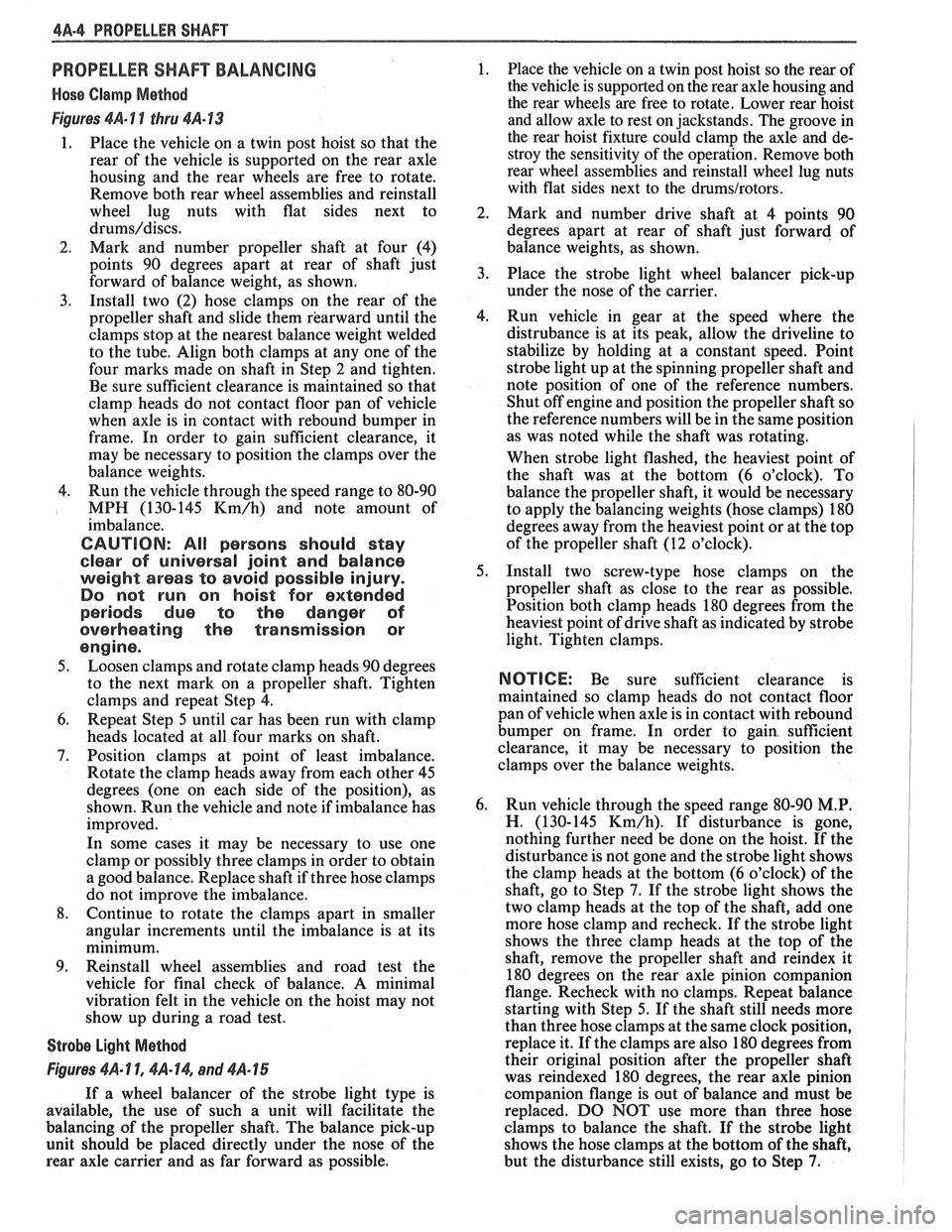
1. Place the vehicle on a twin post hoist so that the
rear of the vehicle is supported on the rear axle
housing and the rear wheels are free to rotate.
Remove both rear wheel assemblies and reinstall
wheel lug nuts with flat sides next to
drums/discs.
2. Mark and number propeller shaft at four (4)
points 90 degrees apart at rear of shaft just
forward of balance weight, as shown.
3. Install two (2) hose clamps on the rear of the
propeller shaft and slide them rearward until the
clamps stop at the nearest balance weight welded
to the tube. Align both clamps at any one of the
four marks made on shaft in Step 2 and tighten.
Be sure sufficient clearance is maintained so that
clamp heads do not contact floor pan of vehicle
when axle is in contact with rebound bumper in
frame. In order to gain sufficient clearance, it
may be necessary to position the clamps over the
balance weights.
4. Run the vehicle through the speed range to 80-90
MPH (130-145
Km/h) and note amount of
imbalance.
CAUTION: All persons should stay
clear of universal joint and balance
weight areas to avoid possible injury.
Do not run on hoist for extended
periods due to the danger of
overheating the transmission or
engine.
5. Loosen clamps and rotate clamp heads 90 degrees
to the next mark on a propeller shaft. Tighten
clamps and repeat Step 4.
6. Repeat Step 5 until car has been run with clamp
heads located at all four marks on shaft.
7. Position clamps at point of least imbalance.
Rotate the clamp heads away from each other 45
degrees (one on each side of the position), as
shown. Run the vehicle and note if imbalance has
improved.
In some cases it may be necessary to use one
clamp or possibly three clamps in order to obtain
a good balance. Replace shaft if three hose clamps
do not improve the imbalance.
8. Continue to rotate the clamps apart in smaller
angular increments until the imbalance is at its
minimum.
9. Reinstall wheel assemblies and road test the
vehicle for final check of balance. A minimal
vibration felt in the vehicle on the hoist may not
show up during a road test.
Strobe Light Method
Figures 461- 1 1, $A- 14, and 4A- 15
If a wheel balancer of the strobe light type is
available, the use of such a unit will facilitate the
balancing of the propeller shaft. The balance pick-up
unit should be placed directly under the nose of the
rear axle carrier and as far forward as possible. 1.
Place
the vehicle on a twin post hoist so the rear of
the vehicle is supported on the rear axle housing and
the rear wheels are free to rotate. Lower rear hoist
and allow axle to rest on jackstands. The groove in
the rear hoist fixture could clamp the axle and de-
stroy the sensitivity of the operation. Remove both
rear wheel assemblies and reinstall wheel lug nuts
with flat sides next to the
drums/rotors.
2.
Mark and number drive shaft at 4 points 90
degrees apart at rear of shaft just forward of
balance weights, as shown.
3. Place the strobe light wheel balancer pick-up
under the nose of the carrier.
4. Run vehicle in gear at the speed where the
distrubance is at its peak, allow the driveline to
stabilize by holding at a constant speed. Point
strobe light up at the spinning propeller shaft and
note position of one of the reference numbers.
Shut off engine and position the propeller shaft so
the reference numbers will be in the same position
as was noted while the shaft was rotating.
When strobe light flashed, the heaviest point of
the shaft was at the bottom (6 o'clock). To
balance the propeller shaft, it would be necessary
to apply the balancing weights (hose clamps) 180
degrees away from the heaviest point or at the top
of the propeller shaft (12 o'clock).
5. Install two screw-type hose clamps on the
propeller shaft as close to the rear as possible.
Position both clamp heads 180 degrees from the
heaviest point of drive shaft as indicated by strobe
light. Tighten clamps.
NOTICE: Be sure sufficient clearance is
maintained so clamp heads do not contact floor
pan of vehicle when axle is in contact with rebound
bumper on frame. In order to gain. sufficient
clearance, it may be necessary to position the
clamps over the balance weights.
6. Run vehicle through the speed range 80-90
M.P.
H. (130-145 Km/h). If disturbance is gone,
nothing further need be done on the hoist. If the
disturbance is not gone and the strobe light shows
the clamp heads at the bottom (6 o'clock) of the
shaft, go to Step
7. If the strobe light shows the
two clamp heads at the top of the shaft, add one
more hose clamp and recheck. If the strobe light
shows the three clamp heads at the top of the
shaft, remove the propeller shaft and
reindex it
180 degrees on the rear axle pinion companion
flange. Recheck with no clamps. Repeat balance
starting with Step 5. If the shaft still needs more
than three hose clamps at the same clock position,
replace it. If the clamps are also 180 degrees from
their original position after the propeller shaft
was reindexed 180 degrees, the rear axle pinion
companion flange is out of balance and must be
replaced. DO NOT use more than three hose
clamps to balance the shaft. If the strobe light
shows the hose clamps at the bottom of the shaft,
but the disturbance still exists, go to Step
7.