1988 PONTIAC FIERO transmission oil
[x] Cancel search: transmission oilPage 551 of 1825
6EZ-B-4 5.OL (VIN E) DRIVEABILITY AND EMISSIONS
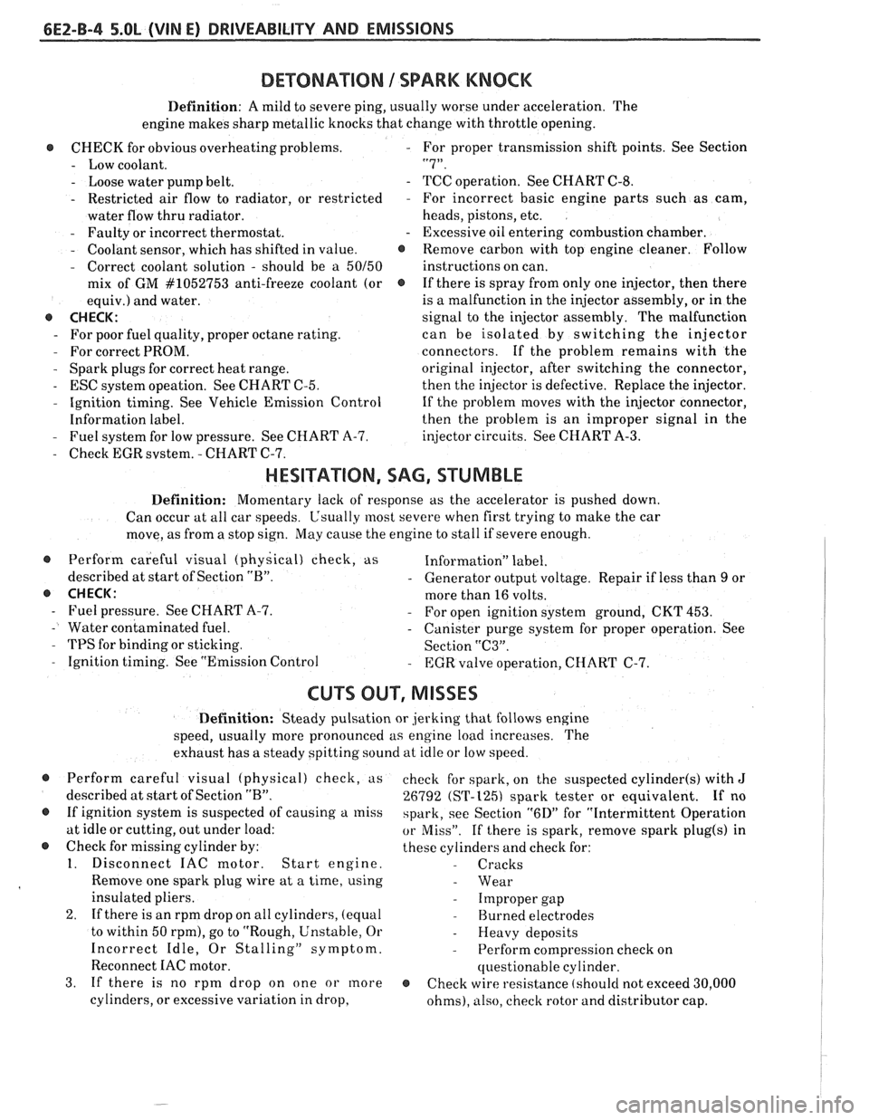
DEWNATION 1 SPARK KNOCK
Definition: A mild to severe ping, usually worse under acceleration. The
engine makes sharp metallic knocks that change with throttle opening.
@ CHECK for obvious overheatingproblems. - For proper transmission shift points. See Section
- Low coolant. "7".
- Loose water pump belt. - TCC operation. See CHART C-8.
- Restricted air flow to radiator, or restricted - For incorrect basic engine parts such as cam,
water flow thru radiator. heads,
pistons, etc.
- Faulty or incorrect thermostat. - Excessive oil entering combustion chamber.
- Coolant sensor, which has shifted in value. @ Remove carbon with top engine cleaner. Follow
- Correct coolant solution - should be a 50150 instructions on can.
mix of GM
#lo52753 anti-freeze coolant (or @ If there is spray from only one injector, then there
equiv.) and water. is
a malfunction in the injector assembly, or in the
@ CHECK: signal to the injector assembly. The malfunction
- For poor fuel quality, proper octane rating. can be isolated by switching the injector
- For correct PROM. connectors. If the problem remains with the
- Spark plugs for correct heat range.
original injector, after switching the connector,
- ESC system opeation. See CHART C-5.
then the injector is defective. Replace the injector.
- Ignition timing. See Vehicle Emission Control
If the problem moves with the injector connector,
Information label. then the
problem is an improper signal in the
- Fuel system for low pressure. See CHART A-7.
injector circuits. See CHART A-3.
- Check EGR svstem. - CHART C-7.
HESITATION, SAG, STUMBLE
Definition: Momentary lack of response as the accelerator is pushed down.
Can occur at all car speeds.
C'sually most severe when first trying to make the car
move, as from a stop sign.
May cause the engine to stall if severe enough.
@ Perform careful visual (physical) check, as Information" label.
described at start of Section
"B". - Generator output voltage. Repair if less than 9 or
@ CHECK: more than 16 volts.
- Fuel pressure. See CHART A-7. - For open ignition system ground, CKT 453.
- Water contaminated fuel. - Canister purge system for proper operation. See
- TPS for binding or sticking.
Section "C3".
- Ignition timing. See "Emission Control - EGR valve operation, CHART C-7.
CU"F OUT, MISSES
Definition: Steady pulsation or jerking that follows engine
speed, usually more pronounced as engine load increases. The
exhaust has a steady spitting sound at idle or low speed.
@ Perform careful visual (physical) check, us
described at start of Section
"B".
@ If ignition system is suspected of causing a miss
at idle or cutting, out under load:
@ Check for missing cylinder by:
1. Disconnect IAC motor. Start engine.
Remove one spark plug wire at a time, using
insulated pliers.
2. If there is an rpm drop on all cylinders, (equal
to within 50
rpm), go to "Rough, Unstable, Or
Incorrect Idle, Or Stalling" symptom.
Reconnect
IAC motor.
3. If there is no rpm drop on one or more
cylinders, or excessive variation in drop, check
for spark, on the suspected
cylinder(s) with J
26792 (ST-1251 spark tester or equivalent. If no
spark, see Section
"6D" for "Intermittent Operation
or Miss". If there is spark, remove spark plug(s) in
these cylinders and check for:
- Cracks
- Wear
- Improper gap
- Burned electrodes
- Heavy deposits
- Perform compression check on
questionable cylinder.
@ Check wire resistance (shoulcl not exceed 30,000
ohms), also, check rotor and distributor cap.
Page 588 of 1825
DRIVEABILITY AND EMISSIONS - S.0L (VIN E) 6EZ-C2-13
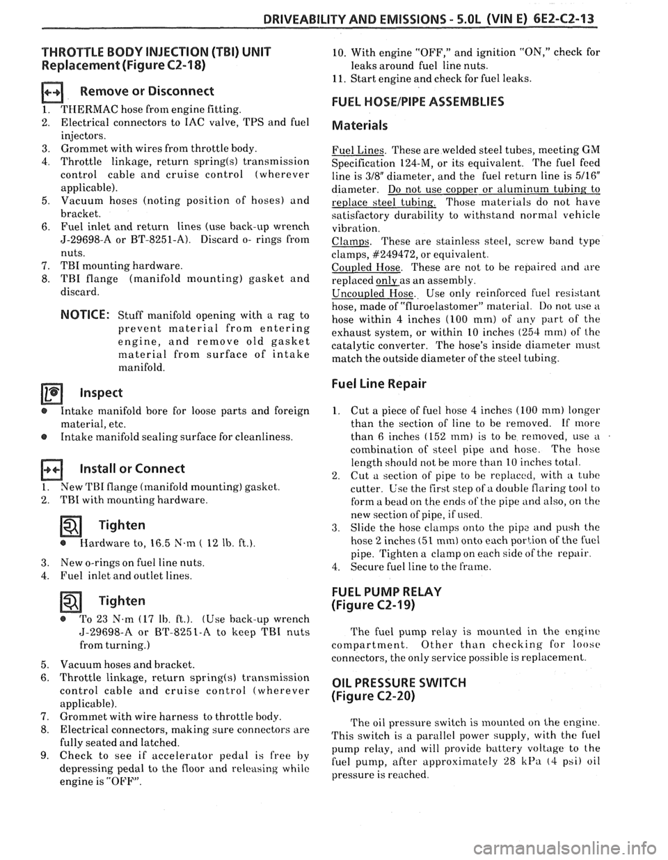
"THROTTLE BODY INJECTION (TBI) UNIT
Replacement (Figure C2-18)
a Remove or Disconnect
1. THERMAC hose from engine fitting.
2. Electrical connectors to IAC valve, TPS and fuel
injectors.
3. Grommet with wires from throttle body.
4. Throttle linkage, return
spring(s) transmission
control cable and cruise control (wherever
applicable).
5. Vacuum hoses (noting position of hoses) and
bracket.
6. Fuel inlet and return lines (use back-up wrench
J-29698-A or BT-8251-A). Discard o-
rings from
nuts.
7. TBI mounting hardware.
8. TBI flange (manifold mounting) gasket and
discard.
NOTICE: Stuff manifold opening with a rag to
prevent material from entering
engine, and remove old gasket
material from surface of intake
manifold.
Inspect
@ Intake manifold bore for loose parts and foreign
material, etc.
@ Intake manifold sealing surface for cleanliness.
Install or Connect
1. New TBI flange (manifold mounting) gasket.
2.
TI31 with mounting hardware.
Tighten
@ Hardwareto, 16.5N-m( 12Ib. ft.).
3. New o-rings on fuel line nuts
4. Fuel inlet and outlet lines.
Tighten - @ To 23 N.m (17 lb. ft.). (Use back-up wrench
J-29698-A or BT-8251-A to keep TBI nuts
from turning.)
5. Vacuum hoses and bracket.
6. Throttle linkage, return
spring(s) transmission
control cable and cruise control (wherever
applicable).
7. Grommet with wire harness to throttle body.
8. Electrical connectors, making sure connectors are
fully seated and latched.
9. Check to see if accelerator pedal is free by
depressing pedal to the floor
and releasing while
engine is "OFF".
10. With engine "OFF," and ignition "ON," check for
leaks around fuel line nuts.
11. Start engine and check for fuel leaks.
FUEL HOSEIPIPE ASSEMBLIES
Materials
Fuel Lines. These are welded steel tubes, meeting GM
Specification 124-M, or its equivalent. The fuel feed
line is
318" diameter, and the fuel return line is 5/16"
diameter. Do not use copper or aluminum tubing to
replace steel tubing. Those materials do not have
satisfactory durability to withstand normal vehicle
vibr, ii t' lon.
Clamps. These are stainless steel, screw band type
clamps,
#249472, or equivalent.
Coupled Hose. These are not to be repaired and are
replaced
&as an assembly.
Uncoupled Hose. Use only reinforced fuel resistant
hose, made of "fluroelastomer" material.
[lo not use w
hose within 4 inches (100 mm) of any part of the
exhaust system, or within 10 inches
(254 mm) of the
catalytic converter. The hose's inside diameter nus st
match the outside diameter of the steel tubing.
Fuel Line Repair
1. Cut
a piece of fuel hose 4 inches (100 mm) longer
than the section of line to be removed. If
more
than 6 inches (152 tnm) is to be removed, use a .
combination of steel pipe and hose. The
hose
length should not be more than 10 inches total.
2. Cut a section of pipe to be replacccl, with a tube
cutter. C'se the first step of a double flaring tool to
form a bead on the ends
of the pipe and also, on the
new section of pipe, if used.
3. Slide
the hose
clanlps onto the pip2 and push the
hose
2 inches (51 mm) onto each portion of the fuel
pipe. Tighten a
clamp on each side of the repair.
4. Secure
fuel line to the frame.
FUEL PUMP RELAY
(Figure
CZ-19)
The fuel pump relay is mounted in the engine
compartment. Other than checking for loose
connectors, the only service possible is replacement.
OIL PRESSURE SWITCH
(Figure C2-20)
The oil pressure switch is li~ounted on the engine.
This switch is a parallel power supply, with the fuel
pump relay, and will provide battery voltage to the
fuel
pump, after approximately 28 kPa (4 psi) oil
pressure is reached.
Page 629 of 1825

6EZ-C8-4 DRIVEABILITY AND EMISSIONS - 5.OL (VIN E)
I5 WAY (FRONT VIEW)
SPEED INPUT
4rH GEAR SIGNAL
422 TANIBLK
ALDL CONNECTOR
CHART C-8A
TRANSMISSION CONVERTER CLUTCH (TCC)
ELECTRICAL DIAGNOSIS
(Page 1 of 2)
5.OL (VIN E) "F" "SERIES (TBI)
Circuit Description:
The purpose of the automatic transmission torque converter clutch is to eliminate the power loss of the
torque converter, when the vehicle is in a cruise condition. This allows the convenience of the automatic
transmission and the fuel economy of a manual transmission.
Fused battery ignition is supplied to the TCC solenoid through the brake switch. the ECM will engage
TCC
by grounding CKT 422 to energize the solenoid.
TCC will engage when:
- Vehicle speed above 24 mph - Engine at normal operating temperature (above 70°C, 156°F)
- Throttle position sensor output not changing, indicating a steady road speed
- Brake switch closed
Test Description: Numbers below refer to circled solenoids
and relays before installing a
numbers on the diagnostic chart. replacement ECM. Replace
any solenoid or relay
1. Confirms 12 volt supply as well as continuity of that
measures less than 20 ohms.
TCC circuit.
2. Grounding the diagnostic terminal with engine Diagnostic Aids:
"OFF", should energize the capability of the ECM An
engine coolant thermostat that is stuck open or
to control the solenoid. opens
at too low a temperature, may result in an
3. Solenoid coil resistance must measure more than inoperative TCC.
20 ohms. Less resistance will cause early failure
of the ECM
drive^.". Using an ohmmeter, check
the solenoid coil resistance of
all ECM controlled
Page 631 of 1825
6E2-C8-6 DRIVEABILITY AND EMISSIONS - 5.OL (VIN E)
I.P. HARNESS CONNECTOR 15 WAY (FRONT VIEW)
ECM
VEHICLE SPEED SIGNAL
SPEED INPUT
4TH GEAR SIGNAL
422 TANIBLK
ALDL CONNECTOR
* 85 4435-66 6-8-87
CHART C-8A
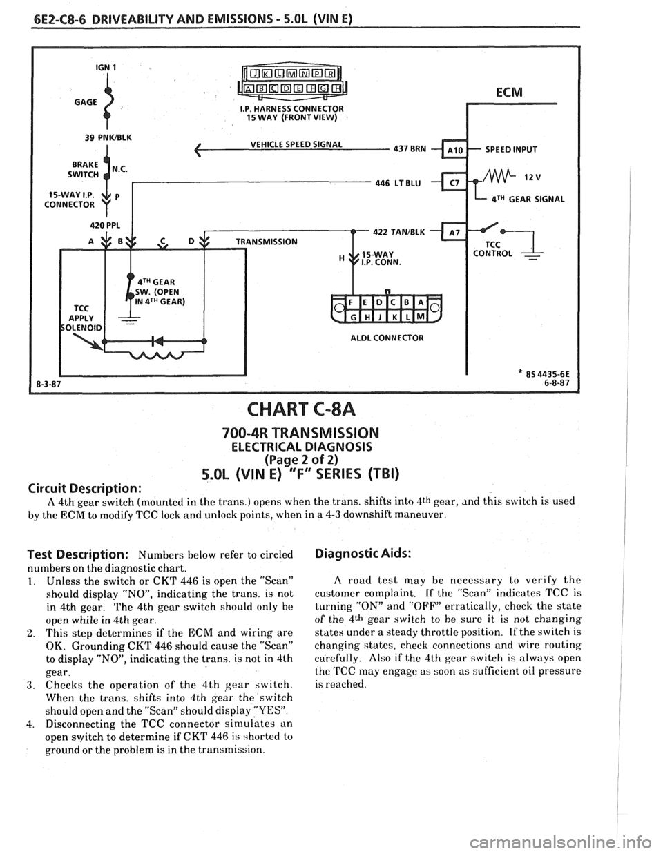
700-4R TRANSMISSION
ELECTRICAL DIAGNOSIS
(Page 2 of 2)
5.0L (VIN E) "F" "SERIES (TBI)
Circuit Description:
A 4th gear switch (mounted in the trans.) opens when the trans. shifts into 4th gear, and this switch is used
by the ECM to modify TCC lock and unlock points, when in a 4-3 downshift maneuver.
Test Description: Numbers below refer to circled
numbers on the diagnostic chart.
1. Unless the switch or CKT 446 is open the "Scan"
should display "NO", indicating the trans. is not
in 4th gear.
The 4th gear switch should only he
open whiie in 4th gear.
2. This step determines if the ECM and wiring are
OK. Grounding CKT 446 should cause the "Scan"
to display "NO", indicating the trans. is not in 4th
gear.
3. Checks the operation of the 4th gear switch.
When the trans. shifts into 4th
geir the switch
should open and the "Scan" should display
"YES".
4. Disconnecting the TCC connector simulates an
open switch to determine if CKT
446 is shorted to
ground or the problem is in the transmission.
Diagnostic Aids:
A road test may be necessary to verify the
customer complaint. If the "Scan" indicates TCC is
turning
"ON" and "OFF" erratically, check the state
of the 4th gear switch to he sure it is not changing
states under a steady throttle position.
If the switch is
changing states, check connections and wire routing
carefully. Also if the 4th gear switch is always open
the
TCC may engage as soon as sufficient oil pressure
is reached.
Page 644 of 1825
INDEX
SECT ION PAGE
Diagnosis ......................... C1.5. 16
Service
........................... C1-8
MAT Sensor
General Description
.................. C1-2
Diagnosis
......................... C1-5
Service
........................... C1-7
Minimum
Idle Speed Adjustment ......... C2-14
Misses
.............................. B-4
Negative Backpressure Valve
............ C7-1
Non-Adjustable TPS Output Check
........ C2-14
Oil Pressure Switch
.................... C2-16
Oxygen Sensor
(02)
General Description ................. C1-3
Diagnosis ......................... C1-5
Service
........................... C1-9
Open Loop
.......................... C2-2
Park Neutral Switch
General Description
................. C1-4
Diagnosis
.......................... C1-5
C1-12
Service. Parts Information
............. C1-9
Poor Fuel Economy
.................... B.5.
C5- 1
Poor Performance
.................... C5-1
Positive Crankcase Ventilation (PCV)
General Description. Diagnosis
......... C13-1
Service. Parts Information
............. C13-2
Pressure Regulator
.................... C2-3
PROM General Description
................. C1-1
Diagnosis ......................... C1-5
Service
........................... C1-6
....................... Quad Drivers. C1-4
Reference Signal
...................... C1-5
Rough
Idle .......................... B-5
RunMode ........................... C2-2
SECTION PAGE
S
Sag ................................ B-4
"Scan" Data
......................... A-8
Sensor Information
.................... C1-2-9
Setting Timing
....................... C4-2
Shift Light
........................... C8-8
Sluggish
............................ B-3
Spark Knock
......................... B-4
Spongy
............................. 8-3
Stalling ............................. B-5
Starting Mode
........................ C2-1
Stumble
............................ B-4
Surges
............................. B-3
Table Of Contents
.................... A-1
Tank Pressure Control Valve
General Description
................. C3-2
Diagnosis
......................... C3-3
Throttle Body Injection Unit
General Description
................. C2-3
Service
........................... C2-7
C2- 14
Throttle Position Sensor
................ C2-5
General Description
................. C1-3
Diagnosis
......................... C1-5
Service
........................... C1-9
C2- 12
Transmission Converter Clutch TCC System
General Description
................. C8-1
Diagnosis
......................... C8-2
C8-4 C8-6
Parts Information
................... C8-2
Unstable
Idle ........................ B-5
....................... Vapor Canister C3-1
Vehicle Speed Sensor (VSS)
.................. General Description C1-4
Diagnosis
......................... 4.5
..................... Wiring Diagrams 8-3
Page 648 of 1825
DRlVEABlLlTVAND EMISSIONS 2.8L (VIN S). 5.OL (VIN F) & 5.7L (VIN 8) 6E3-3
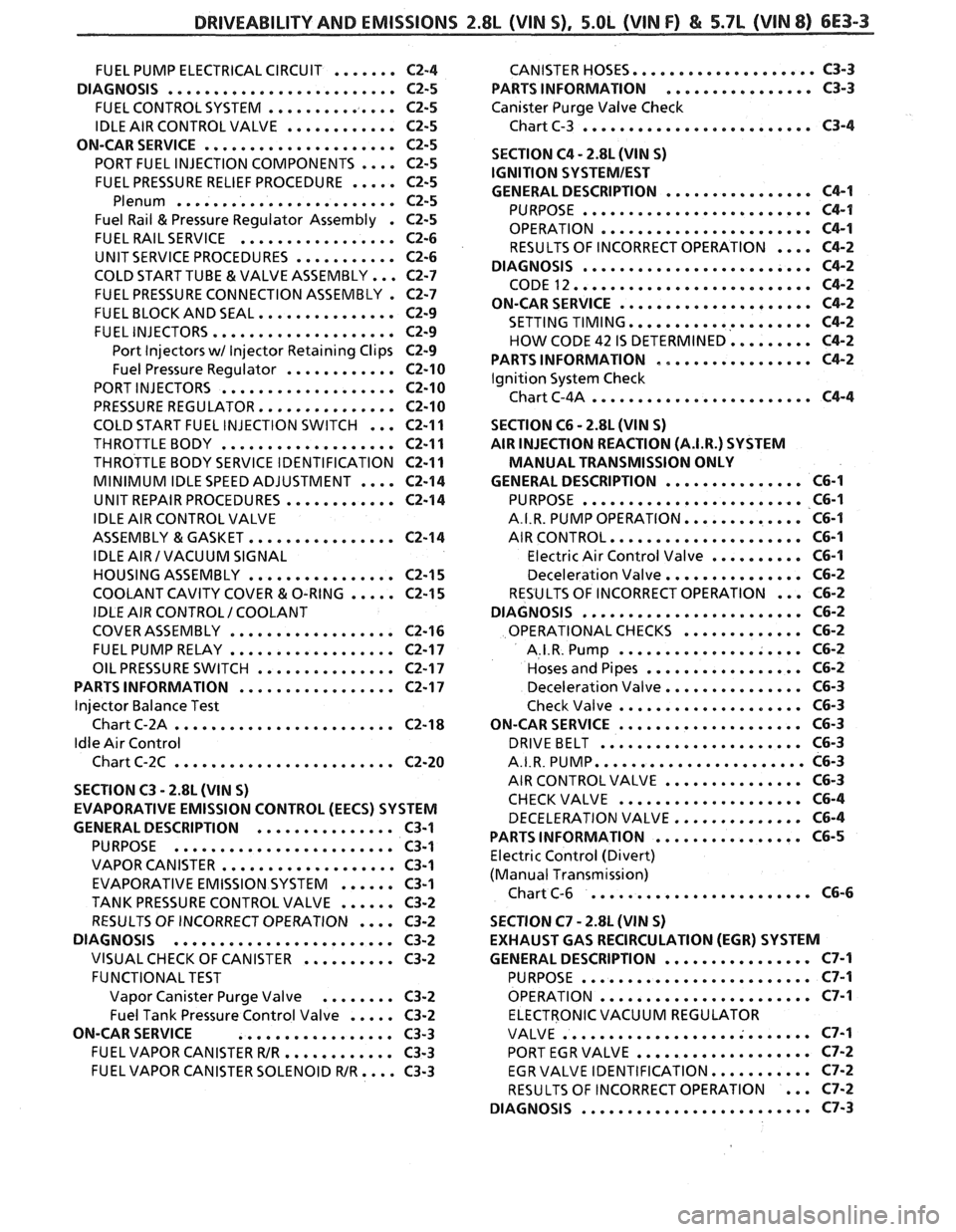
.................... FUEL PUMP ELECTRICAL CIRCUIT ....... C2-4 CANISTER HOSES C3-3
................ DIAGNOSIS ......................... C2-5 PARTS INFORMATION C3-3
FUEL CONTROL SYSTEM .............. C2-5 Canister Purge Valve Check
......................... IDLE AIR CONTROL VALVE ............ C2-5 Chart C-3 C3-4
ON-CAR SERVICE
..................... C2-5
.... PORT FUEL INJECTION COMPONENTS C2-5
FUEL PRESSURE RELIEF PROCEDURE ..... C2-5
Plenum ........................ C2-5
Fuel Rail & Pressure Regulator Assembly . C2-5
FUEL RAIL SERVICE ................. C2-6
UNIT SERVICE PROCEDURES ........... C2-6
COLD START TUBE & VALVE ASSEMBLY ... C2-7
FUEL PRESSURE CONNECTION ASSEMBLY . C2-7
FUEL BLOCK AND SEAL ............... C2-9
FUEL INJECTORS .................... C2-9
Port Injectors wl Injector Retaining Clips C2-9
Fuel Pressure Regulator ............ C2-10
PORT INJECTORS ................... C2-10
PRESSURE REGULATOR ............... C2-10
COLD START FUEL INJECTION SWITCH ...
THROTTLE BODY ...................
THROTTLE BODY SERVICE IDENTIFICATION
MINIMUM IDLE SPEED ADJUSTMENT
....
UNIT REPAIR PROCEDURES ............
IDLE AIR CONTROL VALVE
ASSEMBLY
& GASKET ................
IDLE AIR I VACUUM SIGNAL
HOUSING ASSEMBLY
................
COOLANT CAVITY COVER & O-RING .....
IDLE AIR CONTROL I COOLANT
COVER ASSEMBLY
..................
FUEL PUMP RELAY ..................
OIL PRESSURE SWITCH ...............
PARTS INFORMATION .................
Injector Balance Test
Chart C-2A
........................
Idle Air Control
Chart C-2C
........................
SECTION C3 . 2.8L (WIN S)
EVAPORATIVE EMISSION CONTROL (EECS) SYSTEM
GENERAL
DESCRIPTION ............... C3-1
PURPOSE ........................ C3-1
VAPOR CANISTER ................... C3-1
EVAPORATIVE EMISSION SYSTEM ...... C3-1
TANK PRESSURE CONTROL VALVE ...... C3-2
.... RESULTS OF INCORRECT OPERATION C3-2
DIAGNOSIS
........................ C3-2
VISUAL CHECK OF CANISTER .......... C3-2
FUNCTIONAL TEST
Vapor Canister Purge Valve
........ C3-2
..... Fuel Tank Pressure Control Valve C3-2
ON-CAR SERVICE
................. C3-3
FUEL VAPOR CANISTER WR ............ C3-3
FUEL VAPOR CANISTER SOLENOID WR .... C3-3
SECTION C4 . 2.8L (VIN S)
IGNITION
SQSTEMIEST
................ GENERAL DESCRIPTION C4-1
......................... PURPOSE C4-1
OPERATION ....................... C4-1
RESULTS OF INCORRECT OPERATION .... C4-2
DIAGNOSIS
......................... C4-2
CODE 12 .......................... C4-2
ON-CAR SERVICE ..................... C4-2
SETTING TIMING .................... C4-2
HOW CODE 42 IS DETERMINED ......... C4-2
PARTS INFORMATION ................. C4-2
Ignition System Check
Chart C-4A
........................ C4-4
SECTION C6 . 2.8L (VIN S)
AIR INJECTION REACTION (A.I.R.) SYSTEM
MANUAL TRANSMISSION ONLY
............... GENERAL DESCRIPTION C6-1
........................ PURPOSE C6-1
............. A.I.R. PUMP OPERATION C6-I
..................... AIR CONTROL C6-1
.......... Electric Air Control Valve C6-1
............... Deceleration Valve C6-2
... RESULTS OF INCORRECT OPERATION C6-2
........................ DIAGNOSIS C6-2
............. OPERATIONAL CHECKS C6-2
.................... A.I.R. Pump C6-2
................. Hoses and Pipes C6-2
............... Deceleration Valve C6-3
.................... Check Valve C6-3
.................... ON-CAR SERVICE C6-3
...................... DRIVEBELT C6-3
....................... A.I.R. PUMP C6-3
............... AIR CONTROL VALVE C6-3
.................... CHECKVALVE C6-4
DECELERATION VALVE .............. C6-4
................ PARTS INFORMATION C6-5
Electric Control (Divert)
(Manual Transmission)
........................ Chart C-6 C6-6
SECTION C7
. 2.8L (VIN S)
EXHAUST GAS RECIRCULATION (EGR) SYSTEM
GENERAL DESCRIPTION
................ C7-1
......................... PURPOSE C7-1
....................... OPERATION C7-I
ELECTRONIC VACUUM REGULATOR
........................... VALVE C7-1
................... PORT EGR VALVE C7-2
........... EGR VALVE IDENTIFICATION C7-2
... RESULTS OF INCORRECT OPERATION C7-2
......................... DIAGNOSIS C7-3
Page 712 of 1825
DRIVEABILITY AND EMISSIONS 2.8L (VIN S) 6E3-B-3
e A faulty in-tank fuel pump check valve will @ If engine starts but then immediately stalls,
allow the fuel in the lines to drain back to the open
distributor by-pass line. If engine then
tank after the engine is stopped. To check for starts
and runs OK, replace pickup coil.
this condition:
@ If engine starts and stalls, disconnect MAF
Perform Fuel System Diagnosis, CHART A-7. sensor. If engine then runs and sensor
@ Remove spark plugs. Check for wet plugs, connections are OK, replace the sensor.
cracks, wear, improper gap, burned
f lectrodes,
or heavy deposits. Repair or replace as
necessary.
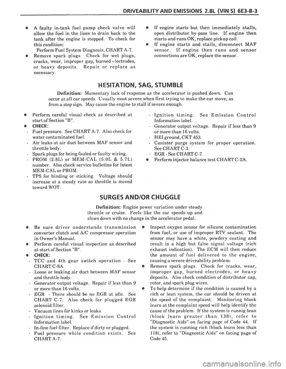
HESITATION, SAG, STUMBLE
Definition: Momentary lack of response as the accelerator is pushed down. Can
occur at all car speeds.
Usually most severe when first trying to make the car move, as
from a stop sign. May cause the engine to stall if severe enough.
Perform careful visual check as described at
start of Section
"B".
a CHECK:
- Fuel pressure. See CHART A-7. Also check for
water contaminated fuel.
- Air leaks at air duct between MAF sensor and
throttle body.
- Spark plugs for being fouled or faulty wiring.
- PROM (2.8L) or MEM-CAL (5.OL & 5.7L)
number. Also check service bulletins for latest
MEM-CAL or PROM.
- TPS for binding or sticking. Voltage should
increase at a steady rate as throttle is moved
toward WOT.
- Ignition timing. See Emission Control
Information label.
- Generator output voltage. Repair if less than 9
or more than 16 volts.
- HE1 ground, CKT 453.
- Canister purge system for proper operation.
See CHART C-3.
- EGR - See CHART C-7.
@ Perform injector balance test CHART C-2A.
SURGES AND/OR CHUGGLE
Definition: Engine power variation under steady
throttle or cruise. Feels like the car speeds up and
slows down with no change in the accelerator pedal.
Be sure driver understands transmission
converter clutch and
A/C compressor operation
in Owner's Manual.
e Perform careful visual inspection as described
at start of Section
"B".
CHECK:
- TCC and 4th gear switch operation - See
CHART C-8A.
- Loose or leaking air duct between MAF sensor
and throttle body.
- Generator output voltage. Repair if less than 9
or more than 16 volts.
- EGR - There should be no EGR at idle. See
CHART C-7. Also check for plugged EGR
solenoid filter.
- Vacuum lines for kinks or leaks.
- Ignition timing. See Emission Control
Information label.
- In-line fuel filter. Replace ifdirty or plugged.
- Fuel pressure while condition exists. See
CHART A-7.
@ Inspect oxygen sensor for silicone contamination
from fuel, or use of improper RTV sealant. The
sensor may have a white, powdery coating and
result in a high but false signal voltage (rich
exhaust indication). The ECM will then reduce
the amount of fuel delivered to the engine,
causing a severe driveability problem.
@ Remove spark plugs. Check for cracks, wear,
improper gap, burned electrodes, or heavy
deposits. Also check condition of distributor cap,
rotor, and spark plug wires.
@ To help determine if the condition is caused by a
rich or lean system, the car should be driven at
the speed of the complaint. Monitoring block
learn at the complaint speed will help identify the
cause of the problem. If the system is runnig lean
(block learn greater than
138), refer to
"Diagnostic Aids" on
facing page of Code 44. If
the system is running rich (block learn less than
118), refer to "Diagnostic Aids" on facing page of
Code 45.
Page 723 of 1825
6E3-Cl-4 2.8L (VIN S) DRIVEABILITY AND EMISSIONS
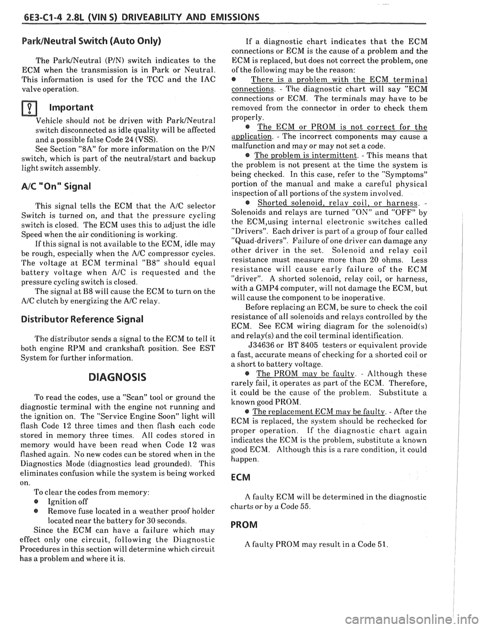
BarWNeutral Switch (Auto Only)
The ParWNeutral (PIN) switch indicates to the
ECM when the transmission is in Park or Neutral.
This information is used for the TCC and the IAC
valve operation.
Important
Vehicle should not be driven with ParWNeutral
switch disconnected as idle quality will be affected
and a possible false Code
24 (VSS).
See Section "$A" for more information on the PIN
switch, which is part of the neutrallstart and backup
light switch assembly.
NC '"n" Signal
This signal tells the ECM that the A/C selector
Switch is turned on, and that the pressure cycling
switch is closed. The ECM uses this to adjust the idle
Speed when the air conditioning is working.
If this signal is not available to the ECM, idle may
be rough, especially when the
A/C compressor cycles.
The voltage at ECM terminal "B8" should equal
battery voltage when
AIC is requested and the
pressure cycling switch is closed.
The signal at
B8 will cause the ECM to turn on the
A/C clutch by energizing the A/C relay.
Distributor Reference Signal
The distributor sends a signal to the ECM to tell it
both engine RPM and crankshaft position. See EST
System for further information.
To read the codes, use a "Scan" tool or ground the
diagnostic terminal with the engine not running and
the ignition on. The "Service Engine Soon" light will
flash Code 12 three times and
then flash each code
stored in memory three times. All codes stored in
memory would have been read when Code 12 was
flashed again. No new codes can be stored when in the
Diagnostics Mode (diagnostics lead grounded).
This
eliminates confusion while the system is being worked
on. To clear the codes from memory:
@ Ignition off
@ Remove fuse located in a weather proof holder
located near the battery for 30 seconds.
Since the ECM can have
a failure which may
effect only one circuit, following the Diagnostic
Procedures in this section will determine which circuit
has a problem and where it is. If
a diagnostic chart indicates that the ECM
connections or ECM is the cause of
a problem and the
ECM is replaced, but does not correct the problem, one
of the following may be the reason:
€9
connections. - The diagnostic chart will say "ECM
connections or ECM. The terminals may have to be
removed from the connector in order to check them
properly.
@ The ECM or PROM is not correct for the
application.
- The incorrect components may cause a
malfunction and may or may not set a code.
@ The problem is intermittent. - This means that
the problem is not present at the time the system is
being checked. In this case, refer to the "Symptoms"
portion of the manual and make a careful physical
inspection of all portions of the system involved.
@ Shorted solenoid, relay coil, or harness. -
Solenoids and relays are turned "ON" and "OFF" by
the
ECM,using internal electronic switches called
"Drivers". Each driver is part of
a group of four called
"Quad-drivers". Failure of one driver can damage any
other driver in the set.
Solelloid and relay coil
resistance must measure more than 20 ohms. Less
resistance will cause early failure of the ECM
"driver". A shorted solenoid, relay coil, or harness,
with a GMP4 computer, will not damage the ECM, but
will cause the component to be inoperative.
Before replacing an ECM, be sure to check the coil
resistance of all solenoids and relays controlled by the
ECM. See ECM wiring diagram for the
solenoid(s)
and relay(s) and the coil terminal identification.
534636 or BT 8405 testers or equivalent provide
a fast, accurate means of checking for a shorted coil or
a short to battery voltage.
@ The PROM may be faulty. - Although these
rarely fail, it operates as part of the ECM. Therefore,
it could be the cause of the problem. Substitute a
known good PROM.
@ The replacement ECM may be faulty. - After the
ECM is replaced, the system should be rechecked for
proper operation. If the diagnostic chart again
indicates the ECM is the problem, substitute
a known
good ECM. Although this is a rare condition, it could
happen.
ECM
A faulty ECM will be determined in the diagnostic
charts or
by a Code 55.
PROM
A faulty PROM may result in a Code 51.