1988 PONTIAC FIERO transmission oil
[x] Cancel search: transmission oilPage 787 of 1825
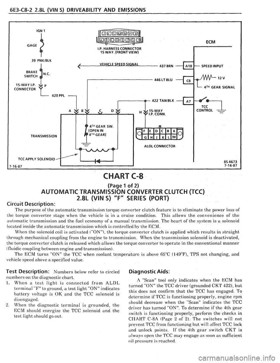
6E3-C8-2 2.8L (VIN S) DRIVEABILITY AND EMISSIONS
VEHICLE SPEED SIGNAL
SPEED INPUT
CONNECTOR
aTH GEAR SIGNAL
422 TAN/BLK
4TH GEAR SW.
TRANSMISSION
ALDL CONNECTOR
TCC APPLY SOLENOID
CHART C-8
(Page 1 of 2)
AUWBMATIC TRANSMISSION CONVERTER CLUTCH (TCC)
2.8L (VIN S) "F" SERIES (PORT)
Circuit Description:
The purpose of the automatic transmission torque converter clutch feature is to eliminate the power loss of
the torque converter stage when the vehicle is in a cruise condition. This allows the convenience of the
automatic transmission and the fuel economy of a manual transmission. The heart of the system is
a solenoid
located inside the automatic transmission which is controlled by the
ECM.
When the solenoid coil is activated ("ON"), the torque converter clutch is applied which results in straight
through mechanical coupling from the engine to transmission. When the transmission solenoid is deactivated,
the torque converter clutch is released which allows the torque converter to operate in the conventional manner
(fluidic coupling between engine and transmission).
The ECM turns
"ON" the 'KC when coolant temperature is above 65°C (14g°F), TPS not changing, and
vehicle speed above a specified value.
Test Description: Numbers below refer to circled Diagnostic Aids:
numbers on the diagnostic chart. A "Scan" tool only indicates when the ECM has 1. When a test light is connected from ALDL turned the TCC driver (grounded CKT 422), but terminal "F" to ground, a test light "ON" indicates
this does not confirm that the TCC has engaged. To battery voltage is OK and the TCC solenoid is
determine if TCC is functioning properly, engine rpm
disengaged.
should decrease when the "ScanJ' indicates the TCC
2. When the diagnostic terminal is grounded, the
driver has turned "ON". To determine if the 4th gear ECM energize the TCC "Ienoid and the switch is functioning properly, perform the checks in
test light should go out.
CIIART C-8A (Page 2 of 2). The switches will not
prevent TCC fi-om functioning but will affect TCC lock
and unlock points. If the 4th gear switch CKT is
always open the
TCC may engage as soon as sufficient
oil
pl.essure is reached.
Page 789 of 1825
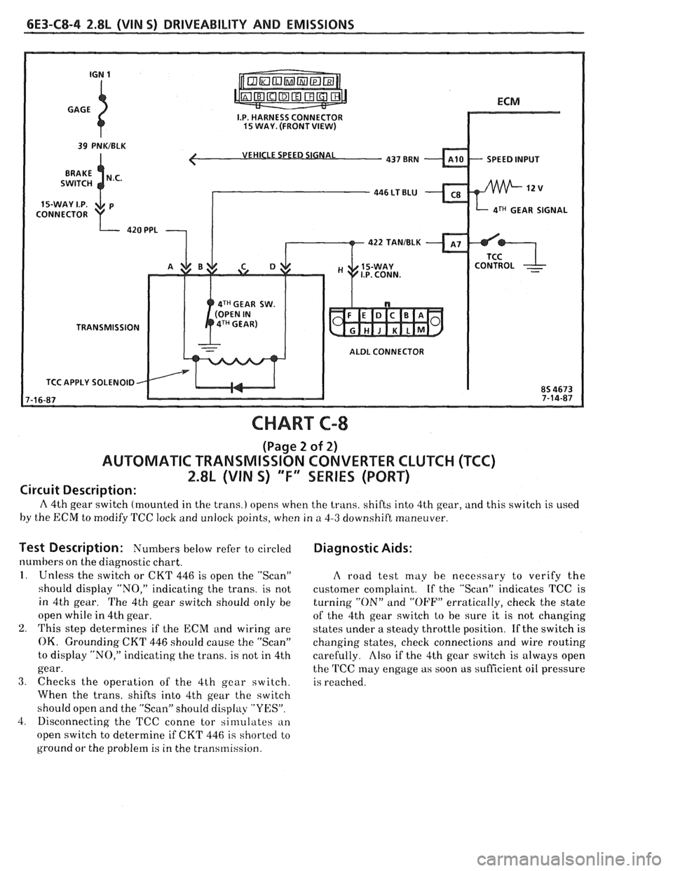
6E3-C8-4 2.8L (VIN 5) DRIVEABILITY AND EMISSIONS
VEHICLE SPEED SIGNAL
4TH GEAR SIGNAL
422 TANIBLK
4TH GEAR SW.
TRANSMISSION
ALDL CONNECTOR
TCC APPLY SOLENOID
CHART C-8
(Page 2 of 2)
AUTOMATIC TRANSMISSION CONVERTER CLUTCH (TCC)
2.8L (VIN S) "F" SERIES (PORT)
Circuit Description:
A 4th gear switch (mounted in the trans.) opens when the trans. shifts into 4th gear, and this switch is used
by the ECM to modify TCC lock and unlock points, when in
a 4-3 downshift maneuver.
Test Description: Numbers I~elow refer to circled
numbers on the diagnostic chart.
1. Unless the switch or CKT 446 is open the "Scan"
should display "NO," indicating the trans. is not
in 4th gear. The 4th gear switch should only be
open while in 4th gear.
2. This step determines if the ECM and wiring are
OK. Grounding CKT 446 should cause the "Scan"
to display "NO," indicating the trans. is not in 4th
gear.
3. Checks the operation of the 4th gear switch.
When the trans. shifts into 4th gear the switch
should open and the "Scan" should display "YES".
4. Disconnecting the
'FCC conne tor sinlulates an
open switch to determine if CKT 446
is shorted to
ground or the problem is in the transmission.
Diagnostic Aids:
A road test may he necessary to verify the
customer complaint. If the "Scan" indicates TCC is
turning
"ON" and "OFF" erratically, check the state
of the 4th gear switch
to be sure it is not changing
states under a steady throttle position. If the switch is
changing states, check connections and wire routing
carefully.
Also if the 4th gear switch is always open
the
'FCC may engage as soon as sufficient oil pressure
is reached.
Page 868 of 1825
DRIVEABILITY AND EMISSIONS 5.OL (VIN F) & 5.7L (VIN 8) 6E3-8-3
@ A faulty in-tank fuel pump check valve will @
allow the fuel in the lines to drain back to the
tank after the engine is stopped. To check for
this condition:
e
Perform Fuel System Diagnosis, CHART A-7.
@ Remove spark plugs. Check for wet plugs,
cracks, wear, improper gap, burned electrodes,
@
or heavy deposits. Repair or replace as
necessary. If
engine starts but then immediately stalls
open distributor by-pass line. If engine then
starts and runs OK, replace pickup coil.
If engine starts and stalls disconnect MAF
sensor. If engine then
r~lns and sensor
connections are OK, replace
thr. )t.ft+rl'.
Basic engine problem.
HESITATION, SAG, STUMBLE
Definition: Momentary lack of response as the accelerator i., pl,ihcc! dowt-
Can occur at all car speeds. Usually most severe when first tryine, lo m,tlir. LII~.
car move, as from a stop sign. May cause the engine to sta!! 1, e er., riu~~~!~
s Perform careful visual check as described at
start of Section
"B".
@ CHECK:
- Fuel pressure. See CHART A-7. Also, check
for water contaminated fuel.
- Air leaks at air duct between MAF sensor and
throttle body.
- Spark plugs for being fouled or faulty wiring.
- Mem-Cal number. Also check service bulletins
for latest Mem-Cal.
- TPS for binding or sticking. Voltage should
increase at
a steady rate as throttle is moved
toward WOT.
- Ignition timing. See emission control
information label.
- Generator output voltage. Repair if less than 9
or more than 16 volts.
- HE1 ground, CKT 453.
- Canister purge system for proper operation.
See CHART C-3.
- EGR - See CHART C-7.
e Perform injector balance test CHART C-2A.
SURGES AND/OR CHUGGLE
Definition: Engine power variation under steady
throttle or cruise. Feels like the car speeds up and
slows down with no change in the accelerator pedal.
@ Be sure driver understands transmission
converter clutch and
AJC compressor operation
in owner's manual.
Perform careful visual inspection as described
at start of Section
"B".
e CHECK:
- Loose or leaking air duct between MAF sensor
and throttle body.
- Generator output voltage. Repair if less than 9
or more than 16 volts.
- EGR - There should be no EGR at idle. See
CHART C-7.
- Vacuum lines for kinks or leaks.
- Ignition timing. See emission control
information label.
- In-line fuel filter. Replace if dirty or plugged.
- Fuel pressure while condition exists. See
CHART A-7.
@ Inspect oxygen sensor for silicon contamination
from fuel, or use of improper RTV sealant. The
sensor may have a white, powdery coating and
result in a high but false signal voltage (rich
exhaust indication). The ECM will then reduce
the amount of fuel delivered to the engine,
causing a severe driveability problem.
@ Remove spark plugs. Check for cracks, wear,
improper gap, burned electrodes, or heavy
deposits. Also check condition of distributor
cap, rotor, and spark plug wires.
@ To help determine if the condition is caused by a
rich or lean system, the car should be driven at
the speed of the complaint. Monitoring block
learn at the complaint speed will help identify
the cause of the problem.
If the system is lean
(block learn greater than
1381, refer to
"Diagnostic Aids"
on facing page of Code 44. If
the system is running rich (block learn less than
1181, refer to "Diagnostic Aids" on facing page
of Code
45.
Page 943 of 1825
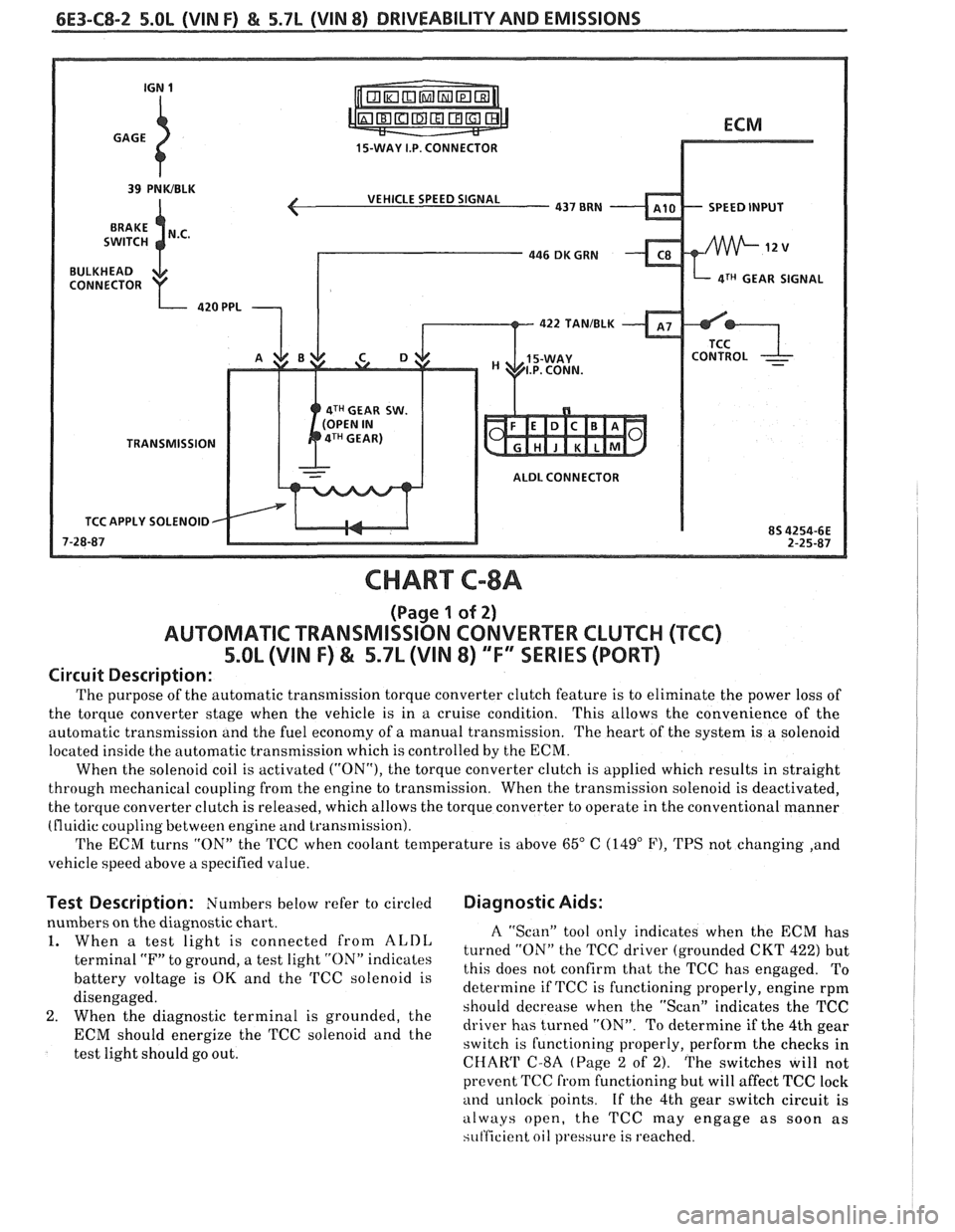
6E3-C8-2 5.OL (VIN F) & 5.7L (VIN 8) DRIVEABILITY AND EMISSIONS
15-WAY I.P. CONNECTOR
VEHICLE SPEED SIGNAL
SPEED INPUT
4TH GEAR SIGNAL
422
TANIBLK
4TH GEAR SW.
TRANSMISSION ALDL CONNECTOR
TCC APPLY SOLENOID
CHART C-8A
(Page 1 of 2)
AUTOMATIC TRANSMISSION CONVERTER CLUTCH (TCC)
5.OL (VIN F) & 5.7L (VIN 8) "F'" SERIES (PORT)
Circuit Description:
The purpose of the automatic transmission torque converter clutch feature is to eliminate the power loss of
the torque converter stage when the vehicle is in a cruise condition. This allows the convenience
of the
automatic transmission and the fuel economy of
a manual transmission. The heart of the system is a solenoid
located inside the automatic transmission which is controlled by the ECM.
When the solenoid coil is activated
("ON"), the torque converter clutch is applied which results in straight
through mechanical coupling from the engine to transmission. When the transmission solenoid is deactivated,
the torque converter clutch is released, which allows the torque converter to operate in the conventional manner
(fluidic coupling between engine
and transmission).
The ECM turns "ON" the TCC when coolant temperature is above
65" C (149" F), TPS not changing ,and
vehicle speed above
a specified value.
Test Description: Numbers below refer to circled Diagnostic Aids:
nbers on the diagnostic chart.
When
a test light is connected from ALDL
terminal "F" to ground, a test light "ON" indicates
battery voltage is
OK and the TCC solenoid is
disengaged.
When the diagnostic terminal is grounded, the
ECM should energize the TCC solenoid and the
test light should go out.
A "Scan" tool only indicates when the ECM has
turned "ON" the TCC driver (grounded CKT
422) but
this does not confirm that the TCC has engaged. To
determine if TCC is functioning properly, engine rpm
should decrease when the "Scan" indicates the TCC
driver has turned "ON". To determine if the 4th gear
switch is functioning properly, perform the checks in
CHAW C-8A (Page 2 of 2). The switches will not
prevent TCC
from functioning but will affect TCC lock
and unlock points. If the 4th gear switch circuit is
always open, the TCC may engage as soon as
si~t'ficient oil pressure is reached.
Page 945 of 1825
6E3-C8-4 5.OL (\/IN F) & 5.7b (VIN 8) DRIVEABILITY AND EMISSIONS
15-WAY I.P. CONNECTOR
SPEED INPUT
4TH GEAR SIGNAL
4TH GEAR SW.
TRANSMISSION
ALDL CONNECTOR
APPLY SOLENOID
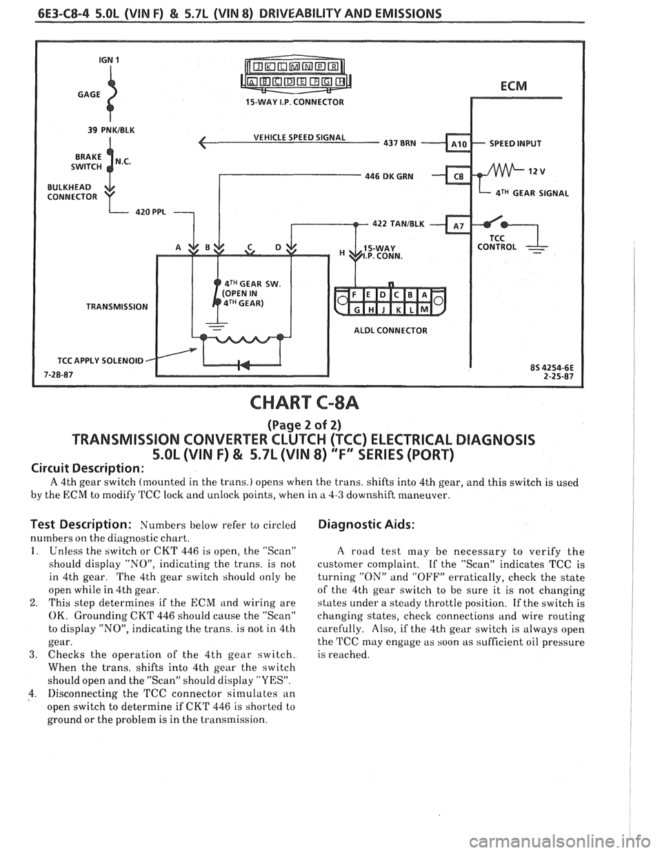
CHART C-8A
(Page 2 of 2)
TRANSMISSION CONVERTER CLUTCH (TCC) ELECTRICAL DIAGNOSIS
5.OL (VIN F) & 5.7L (VIN 8) "F" XRlES (PORT)
Circuit Description:
A 4th gear switch (mounted in the trans.) opens when the trans. shifts into 4th gear, and this switch is used
by the ECM to modify TCC lock and unlock points, when in a 4-3 downshift maneuver.
Test Description: Numbers below refer to circled
numbers on the diagnostic chart.
1. Unless the switch or CKT 446 is open, the "Scan"
should display "NOJ', indicating the trans. is not
in 4th gear. The 4th gear switch should only he
open while in 4th gear.
2. This step determines if the ECM and wiring are
OK. Grounding CKT 446 should cause the "Scan"
to display "NO", indicating the trans. is not in 4th
gear.
3. Checks the operation of the 4th gear switch.
When the trans, shifts into 4th gear the switch
should open and the "Scan" should display "YES".
4. Disconnecting the TCC connector sin~ulates an
open switch to determine if CKT 446 is shorted to
ground or the problem is in the transmission.
Diagnostic Aids:
A road test may be necessary to verify the
customer complaint.
If the "Scan" indicates TCC is
turning
"ON" and "OFF" erratically, check the state
of the 4th gear switch to be sure it is not changing
states under a steady throttle position. If the switch is
changing states, check connections and wire routing
carefully. Also, if the 4th gear switch is always open
the
'l'CC may engage as soon as sufficient oil pressure
is reached.
Page 959 of 1825
INDEX
SECTION PAGE
Cooling Fan Control
................. General Description C12-1
........................ Diagnosis C12-2
........................... Cuts Out B-5
................... Cylinder Select Error A-48
.................... Deceleration Mode C2-3
......................... Detonation B-4
..................... Dieseling. Run On B-6
............. Distributor Reference Signal C1-4
...................... ECM Terminals A-7
.................. ECM Wiring Diagram A3-A6
EGR Control Valve
................. General Description C7-1
................. Valve Identification C7-2
................... Diagnosis. Service C7-2
A-40
.................. EGR Control Solenoid C7-3
......................... EGR Check C7-4
Electronic Control Module
................. General Description C1-1
......................... Diagnosis C1-4
............................ Service C1-5
..................... Function Check C1-7
Electronic Spark Control (ESC) System
................. General Description C5-1
................... Diagnosis. Service C5-4
Electronic Spark Timing EST
............. A-50
A-52
Engine Cranks But Won't Run
............ A-14
........................ Engine Knock C5-4
.......................... ESC Module C5-2
.......................... ESC Sensor C5-1
.................... ESC System Check C5-4
................... ESTllgnition System C4-1
Evaporative Emission Control System
................. General Description C3-1
.......................... Diagnosis C3-2
Exhaust Emissions Excessive (Odors)
....... B-7
Exhaust Gas Recirculation (EGR) System
.... C7-1
Exhaust System Check Restricted
......... B-8
Fuel Control System
................. General Description C2- 1
......................... Diagnosis C2-5
..................... Fuel Cutoff Mode C2-3
SECTION PAGE
Fuel Injectors ........................
Fuel Pressure Connection Assy ............
Fuel Pressure Relief Procedure ...........
Fuel Pump Electrical Circuit .............
Fuel Pump Relay ......................
Fuel Rail
General Description
.................
........................... Service
Fuel System Diagnosis
..................
Fuel System Pressure Test ...............
Fuel Tank Pressure Control Valve .........
.......................... Hard Start B-2
.......... HE1 High Energy Ignition System C4-1
.......................... Hesitation
B-3
............ Idle Air Control System Check C2-20
.................. Idle Air
Control Valve C2-4
......................... Diagnosis C2-5
.................... Ignition System EST C4-1
........ Ignition System Check Integral Coil C4-4
........................ Incorrect Idle B-6
.................. Information Sensors C1.2. 9
.................. Injector
Balance Test C2-18
........................ lntermittents B-2
........................ Knock Sensor C1-3
........................ Lack Of Power B-4
......... Light. Manual Transmission Shift C8-6
.............. Light. Service Engine Soon A-10
MAF Sensor
.................. General Description C1-2
.......................... Diagnosis C1-5
A.42.44. 46
............................ Service C1-8
... Manual Transmission Electrical Diagnosis C8-10
MAT Sensor
.................. General Description C1-2
......................... Diagnosis C1-5
A.34. 38
Page 960 of 1825
INDEX
SECTION
PAGE
MEM -Cal
General Description ................. C1-I
Diagnosis ......................... C1-4
A-60
Service
........................... C1-6
Functional Check
................... C1-7
Minimum
Idle Speed Adjustment ......... C2-12
Misses ............................. 8-5
Negative Backpressure Valve ............ C7-2
No ALDL Data
....................... A- 12
No "Service Engine Soon" Light
.......... A-10
.................... Oil Pressure Switch C2-16
Oxygen Sensor
General Description
.................. C1-3
......................... Diagnosis C1-5
A.24.54. 56
........................... Service C1-8
Park Neutral Switch
General Description
................. C1-3
Diagnosis
.......................... C1-10
C1-5
Service
........................... C1-9
Poor Fuel Economy
.................... B.6.
C5-4
Poor Performance
.................... C5-4
Positive Crankcase Ventilation (PCV)
General Description. Diagnosis
......... C13-1
Service
............................ C13-2
Pressure Regulator
.................... C2-4
........................ Quad Drivers C 1-4
..................... Reference Signal C1-5
.......................... Rough Idle B-6
RunMode .......................... C2-2
RunOn ............................. B-6
SECTION PAGE
................... Sensor Information C1-2-9
"Service Engine Soon" Light On Steady .... A- 12
................... Setting Timing ... . C4-2
.......................... Shift Light C8-6
Sluggish
............................ B-4
......................... Spark Knock B-4
........................ Speed Sensor C8-2
.................. Speedo Buffer Sensor C8-4
Spongy
............................. B-4
............................ Stalling B-6
........................ Starting Mode C2-2
........................... Stumble B-3
Surges
............................. B-3
.................. System Over Voltage A-60
Throttle Body Unit
................. General Description C2-3
........................... Service C2-11
Throttle Position Sensor
................. General Description C1-3
......................... Diagnosis C1-5
A-30
....................... Adjustments C2-12
........................... Service C1-8
Transmission Converter Clutch TCC System
.................. General Description C8-1
......................... Diagnosis C8.2. 4
U
........................ Unstable Idle B-6
V
...................... Vapor Canister C3-1
Vehicle Speed Sensor
.................. General Description C1-3
.......................... Diagnosis C1-5
A-36
Vehicle Anti-Theft System (VATS)
................. General Description A-58
......................... Diagnosis A-59
W
...................... Wiring Diagrams A-3
................... Won't Flash Code 12 A-
12
Sag
.................+............. B-3
......................... "Scan" Data A-8
Page 975 of 1825
6E-14 DRIVEABILITY AND EMISSIONS - FUEL INJECTION
N.O. - NORMALLY OPEN - State of relay contacts
or solenoid plunger when no voltage
is applied.
NOx - NITROGEN, OXIDES OF - One of the
pollutants found in engine exhaust.
O2 - OXYGEN (Sensor) - Monitors the oxygen
content of the exhaust system and generates a voltage
signal to the ECM.
OIL or OILOOP - OPEN LOOP - Describes ECM fuel
control without use of oxygen sensor information.
OUTPUT - Result of a function typically controlled
by the ECM.
OXYGEN SENSOR. EXHAUST - Device that detects
the amount of oxygen
(02) in the exhaust stream.
P.A.1.R - PULSE AIR INJECTION REACTOR system -
pulsed air directed into engine to reduce exhaust
emissions.
PCV - POSITIVE CRANKCASE VENTILATION -
Prevent fumes in crankcase from passing into
atmosphere.
PFI - PORT FUEL INJECTION
PIN
- PARWNEUTWL
PORT - EXHAUST OR INTAKE PORT
PROM
- PROGRAMABLE READ ONLY MEMORY-
an electronic term used to describe the engine
calibration unit
.
RPM - REVOLUTIONS PER MINUTE - A measure of
rotational speed.
RVB - REAR VACUUM BMKE - is used to control
choke operation during cold engine conditions.
SELF-DIAGNOSTIC CODE - The ECM can detect
malfunctions in the system.
If a malfunction occurs,
the ECM turns on the "Service Engine Soon" light.
A
diagnostic code can be obtained from the ECM
through the "Service Engine Soon" light, or by use of a
"Scan" tool. This code will indicate the area of the
malfunction.
SES - SERVICE ENGINE SOON LIGHT - Lights when
a malfunction occurs in Computer Command Control
system.
TACH - TACHOMETER
TBI
- THROTTLE BODY INJECTION (Unit) - is
controlled by the ECM to supply precise airlfuel
mixture into the intake manifold.
TCC - TWNSMISSION I TRANSAXLE CONVERTER
CLUTCH
- ECM controlled solenoid in transmission
which positively couples the transmission to the
engine.
THERMAC - THERMOSTATIC AIR CLEANER -
provides preheated air to intake manifold to provide
better driveability when engine
is cold.
TPS - THROnLE POSITION SENSOR - Device that
tells the ECM the throttle position.
TVS - THERMAL VACUUM SWITCH - Used to
control vacuum in relationship to engine temperature.
V - VOLT
V-6 - SIX CYLINDER ENGINE - Two banks of
cylinders, arranged in a
"V".
V-8 - EIGHT CYLINDER ENGINE - Two banks of
cylinders, arranged in a
"V".
VACUUM - Negative pressure; less than
atmospheric pressure.
VACUUM, MANIFOLD - Vacuum source in
manifold below throttle plate.
VACUUM, PORTED - A vacuum source above I (atmospheric side ) of closed throttle plate. , I
WAC SENSOR - Abbreviation for differential
pressure sensor which is a
vacuum sensor.
VIN - VEHICLE IDENTIFIUTION NUMBER. 1
VSS - VEHICLE SPEED SENSOR - Sensor which
sends vehicle speed information to the ECM.
WASTECATE - A means of controlling the amount
of boost available for a Turbo charged engine.
WOT- WIDE OPEN THROPTLE. I
WIRING HARNESS SERVICE I
The ECM wire harness electrically connects the
ECM to the various solenoids, switches, and sensors in
vehicle engine compartment. The ECM is located
inside the vehicle passenger compartment.
Most connectors in the engine compartment are
protected against moisture and dirt which could create
oxidation and deposits on the terminals. This
protection is important because of the very low voltage
and current levels found in the electronic system. The
connectors have a lock which secures the male and
female terminals together. A secondary lock holds the
seal and terminal into the connector.
GENERAL
Molded-on connectors (like Metri-Pack) require
complete replacement of the connector. This means
splicing a new connector assembly into the harness.