1988 PONTIAC FIERO transmission oil
[x] Cancel search: transmission oilPage 1065 of 1825
700-R4-14 AUTOMATIC TRANSMISSION
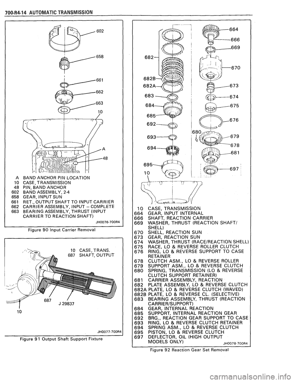
BAND ANCHOR PIN LOCATION
CASE, TRANSMISSION
PIN, BAND ANCHOR
BAND ASSEMBLY,
2-4
GEAR, INPUT SUN
RET., OUTPUT SHAFT TO INPUT CARRIER
CARRIER ASSEMBLY, INPUT
- COMPLETE
BEARING ASSEMBLY, THRUST (INPUT
CARRIER TO REACTION SHAFT)
JH0076-700R4
Figure 90 Input Carrier Removal
10 CASE, TRANS.
687 SHAFT, OUTPUT
10
JH0077-700R4
Figure 91 Output Shaft Support Fixture
10 CASE, TRANSMISSION
664 GEAR, INPUT INTERNAL
666 SHAFT, REACTION CARRIER
669 WASHER, THRUST (REACTION
SHAFT/ SHELL)
670 SHELL, REACTION SUN
673 GEAR, REACTION SUN
674 WASHER, THRUST
(RACEIREACTION SHELL)
675 RACE, LO & REVERSE
ROLLER CLUTCH
676 RING, LO
& REVERSE SUPPORT
TO CASE
RETAINER
678 CLUTCH ASM.,
LO
& REVERSE ROLLER
679 SUPPORT
ASM., LO
& REVERSE CLUTCH
680 SPRING,
TRANSMISSION (LO & REVERSE
CLUTCH SUPPORT RETAINER)
681 CARRIER ASSEMBLY, REACTION
682 PLATE
ASSEMBLY, LO
& REVERSE CLUTCH
682A PLATE, LO
& REVERSE CLUTCH (WAVED)
682B PLATE, LO & REVERSE CL. (SELECTIVE)
683 BEARING ASSEMBLY, THRUST (REACTION
CARRIERISUPPORT) 684 GEAR, INTERNAL REACTION
685 SUPPORT, INTERNAL REACTION GEAR
692 BRG.,
REACTION GEAR SUPPORT TO CASE
693 RING, LO
& REVERSE
CLUTCH RETAINER
694 SPRING
ASM., LO & REVERSE CLUTCH
695 PISTON, LO & REVERSE
CLUTCH
697 DEFLECTOR, OIL (HIGH OUTPUT
MODELS ONLY)
~~0078-700~4
Figure 92 Reaction Gear Set Removal
Page 1068 of 1825
AUTOMATIC TRANSMISSION 700-R4-17
A new third accumulator retainer and ball
assembly
oil feed slots in the retainer must line
up with oil passage in the servo bore.
To be certain of correct installation 653 in.) on the 9.5 mm (3/8")
diameter metal rod. Use it to seat the
third accumulator and ball assembly
as shown. When the scribed line is
flush with the case face, installation
depth is correct.
depth, scribe a mark at
42.0 mm (1.
Page 1071 of 1825
700-R4-20 AUTOMATIC f RANSMlSSlON
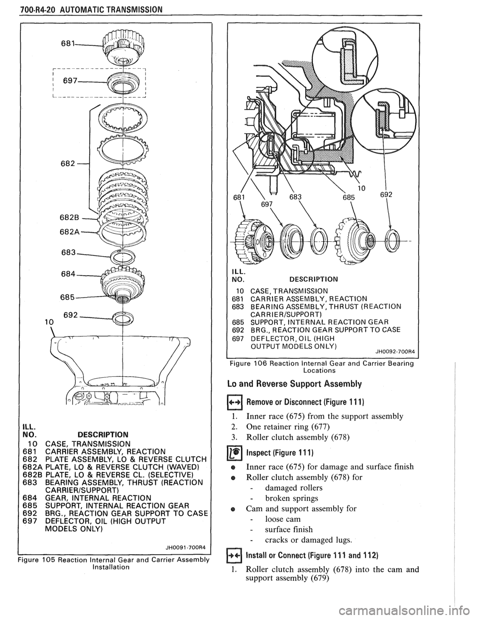
ILL. NO. DESCRIPTION
10 CASE, TRANSMISSION
681 CARRIER ASSEMBLY, REACTION
682 PLATE ASSEMBLY, LO
& REVERSE CLUTCH
682A PLATE, LO
& REVERSE CLUTCH (WAVED) 6828 PLATE, LO & REVERSE CL. (SELECTIVE)
683 BEARING ASSEMBLY, 'THRUST (REACTION
CARRIERISUPPORT) 684 GEAR, INTERNAL REACTION
685 SUPPORT, INTERNAL REACTION GEAR
692 BRG., REACTION GEAR SUPPORT TO CASE
697 DEFLECTOR, OIL (HIGH OUTPUT
MODELS ONLY)
Figure
105 Reaction Internal Gear and Carrier Assembly Installation
ILL.
NO. DESCRIPTION
10 CASE, TRANSMISSION
681 CARRlER ASSEMBLY, REACTION 683 BEARING ASSEMBLY, THRUST (REACTION
CARR I
ER/SUPPORT) 685 SUPPORT, INTERNAL REACTION GEAR 692 BRG., REACTION GEAR SUPPORT TO CASE
697 DEFLECTOR, OIL (HIGH
1 OUTPUT MODELS ONLY) JH0092-700Rd I 1 I Figure 106 Reaction lnternal Gear and Carrier Bearing
Locations
Lo and Reverse Support Assembly
Remove or Disconnect (Figure 11 1)
1. Inner race (675) from the support assembly
2. One retainer ring (677)
3. Roller clutch assembly (678)
@ inspect (figure I 11)
e Inner race (675) for damage and surface finish
a Roller clutch assembly (678) for
- damaged rollers
- broken springs
a Cam and support assembly for
- loose cam
- surface finish
- cracks or damaged lugs.
Install or Connect (Figure 11 1 and 112)
1. Roller clutch assembly (678) into the cam and
support assembly (679)
Page 1076 of 1825
AUTOMATIC TRANSMISSION 700-R4-25
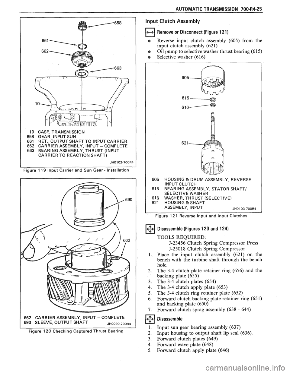
10 CASE, TRANSMISSION
658 GEAR, INPUT SUN 661 RET., OUTPUT SHAFT TO INPUT CARRIER 662 CARRIER ASSEMBLY, INPUT -COMPLETE 663 BEARING ASSEMBLY, THRUST (INPUT
CARRIER TO REACTION SHAFT)
JH0102-700R4
Figure 1 19 lnput Carrier and Sun Gear - Installation
662 CARRIER ASSEMBLY, INPUT -COMPLETE 690 SLEEVE, OUTPUT SHAFT JHOO~O-700~4
Figure 120 Checking Captured Thrust Bearing
lnput Clutch Assembly
Remove or Disconnect (Figure 121)
e Reverse input clutch assembly (605) from the
input clutch assembly (62 1)
e Oil pump to selective washer thrust bearing (61 5)
e Selective washer (616)
605 HOUSING & DRUM ASSEMBLY, REVERSE
INPUT CLUTCH
615 BEARING ASSEMBLY, STATOR SHAFT1 SELECTIVE WASHER
616 WASHER, THRUST (SELECTIVE) 621 HOUSING & SHAFT
ASSEMBLY, INPUT
~~0103-700134
Figure 12 1 Reverse lnput and lnput Clutches
+'+ Disassemble (Figures 123 and 124) (I]
TOOLS REQUIRED:
J-23456 Clutch Spring Compressor Press
J-25018 Clutch Spring Compressor
1. Place the input clutch assembly (621) on the
bench with the turbine shaft through the bench
hole.
2. The 3-4 clutch plate retainer ring (656) and the
backing plate (655)
3. The
3-4 clutch plates (654)
4. The 3-4 clutch apply plate (653)
5. The 3-4 clutch ring retainer plate (652)
6. Forward
clutch backing plate retainer ring (65
1)
and backing plate (650)
7. Forward clutch sprag assembly (638 - 644)
Disassem bie
1. Input sun gear bearing assembly (637)
2. Input
housing to output shaft lip seal (636).
3. Forward clutch plates (649)
4. Forward wave plate (648)
5. Forward clutch apply plate (646)
Page 1077 of 1825
700-84-26 AUTOMATIC TRANSMISSION
SHOULDER
INSTALLATION
A ROD STOCI
620 RETAINER
& CHECK BALL ASSEMBLY
621 HOUSING
& SHAFT ASSEMBLY, INPUT
698 PLUG, ORIFICED CUP JH0104-700R4
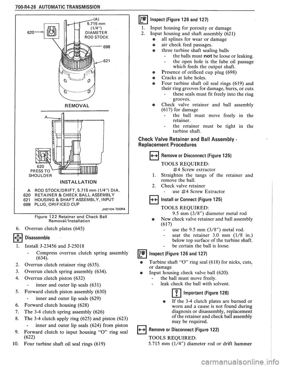
Figure 122 Retainer and Check Ball Removal/lnstallation
6. Overrun clutch plates (645)
Disassemble
1. Install J-23456 and J-25018
- Compress overrun clutch spring assembly
(634).
2. Overrun clutch retainer ring (635).
3. Overrun clutch spring assembly (634).
4. Overrun clutch piston (632)
- inner and outer lip seals (631)
5. Forward clutch piston assembly (630)
- inner and outer lip seals (629)
6. Forward clutch housing (628)
7. The 3-4 clutch spring assembly (626)
8. The 3-4 clutch apply ring (625) and piston (623)
- inner and outer lip seals (624) from piston
9. Forward clutch to input housing
"0" ring seal
(622)
10.
Four turbine shaft oil seal rings (619)
Inspect (figure 126 and 127)
1.
Input housing for porosity or damage
2. Input housing and shaft assembly (621)
all splines for wear or damage
e air check feed passages.
three turbine shaft sealing balls
- the balls must not be loose or leaking. - the open hole is the lube oil passage
which feeds the output shaft.
a Presence of orificed cup plug (698)
a Cracks at lube holes.
@ Four turbine shaft oil seal rings (619) and
their ring grooves for damage, burrs, or cuts
- these seals must fit freely into the ring
grooves.
o Check valve retainer and ball assembly
(617) for damage
- the ball must move freely in the
retainer.
- the retainer must be tight in the
turbine shaft.
Check Valve Retainer and Ball Assembly -
Replacement Procedures
Remove or Disconnect (Figure 125)
TOOLS REQUIRED:
#4 Screw extractor
1. Straighten the tangs of the retainer and
remove the ball.
2. Check valve retainer
- use #4 Screw Extractor
Install or Connect (Figure 125)
TOOLS REQUIRED:
9.5 mm
(3/8") diameter metal rod
e New check valve retainer and ball assembly
(6 17) - use the 9.5 mm (3/8") metal rod.
- seat the retainer 3.0 mm (1/8 in.)
below top surface of the turbine shaft.
- be certain the ball is loose.
lnspect (Figure 126 and 127)
@ Turbine shaft "0" ring seal (61 8) for nicks, cuts,
or damage
Input housing check valve ball (620).
- the ball must move freely. - leak check the ball with solvent.
Important (Figure 126)
o If the 3-4 clutch plates are burned or
worn and a cause is not found during
diagnosis or disassembly, replacement
of the retainer and check ball assembly
may be required.
Remove or Disconnect (Figure 122)
TOOLS REQUIRED:
5.715 mm
(1/4") diameter rod or drift hammer
Page 1084 of 1825
I *ALIGN WIDE NOTCHES TO CASE LUGS (
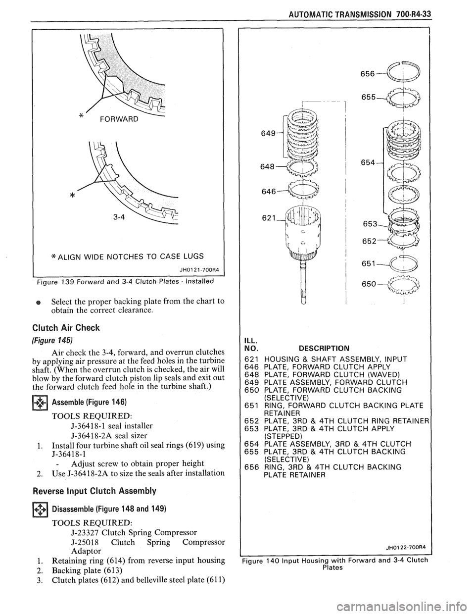
Select the proper backing plate from the chart to
obtain the correct clearance.
Clutch Air Check
(Figure 145)
Air check the 3-4, forward, and overrun clutches
by applying air pressure at the feed holes in the turbine
shaft. (When the overrun clutch is checked, the air will
blow by the forward clutch piston lip seals and exit out
the forward clutch feed hole in the turbine shaft.)
Assemble (Figure 146)
TOOLS REQUIRED:
J-36418- 1 seal installer
J-36418-2A seal sizer
1. Install four turbine
shaft oil seal rings (619) using
J-36418-1
- Adjust screw to obtain proper height
2. Use
J-36418-2A to size the seals after installation
Reverse Input Clutch Assembly
+++ Disassemble (Figure 148 and 149) [I]
TOOLS REQUIRED:
J-23327 Clutch Spring Compressor
J-25018 Clutch Spring Compressor
Adaptor
1. Retaining
ring (614) from reverse input housing
2. Backing plate (613)
3. Clutch plates (612) and belleville steel plate (61 1)
AUTOMATIC TRANSMISSION 700-R4-33
ILL.
NO. DESCRIPTION
621 HOUSING & SHAFT ASSEMBLY, INPUT
646 PLATE, FORWARD CLUTCH APPLY
648 PLATE, FORWARD CLUTCH (WAVED)
649 PLATE ASSEMBLY, FORWARD CLUTCH
650 PLATE, FORWARD CLUTCH BACKING
(SELECTIVE)
651 RING, FORWARD CLUTCH BACKING PLATE
RETAINER
652 PLATE, 3RD
& 4TH CLUTCH RING RETAINE 653 PLATE, 3RD & 4TH CLUTCH APPLY (STEPPED) 654 PLATE ASSEMBLY, 3RD & 4TH CLUTCH
655 PLATE, 3RD & 4TH CLUTCH BACKING
(SELECTIVE)
656 RING, 3RD
& 4TH CLUTCH BACKING
Page 1086 of 1825
AUTOMATIC TRANSMISSION 700.R4-35
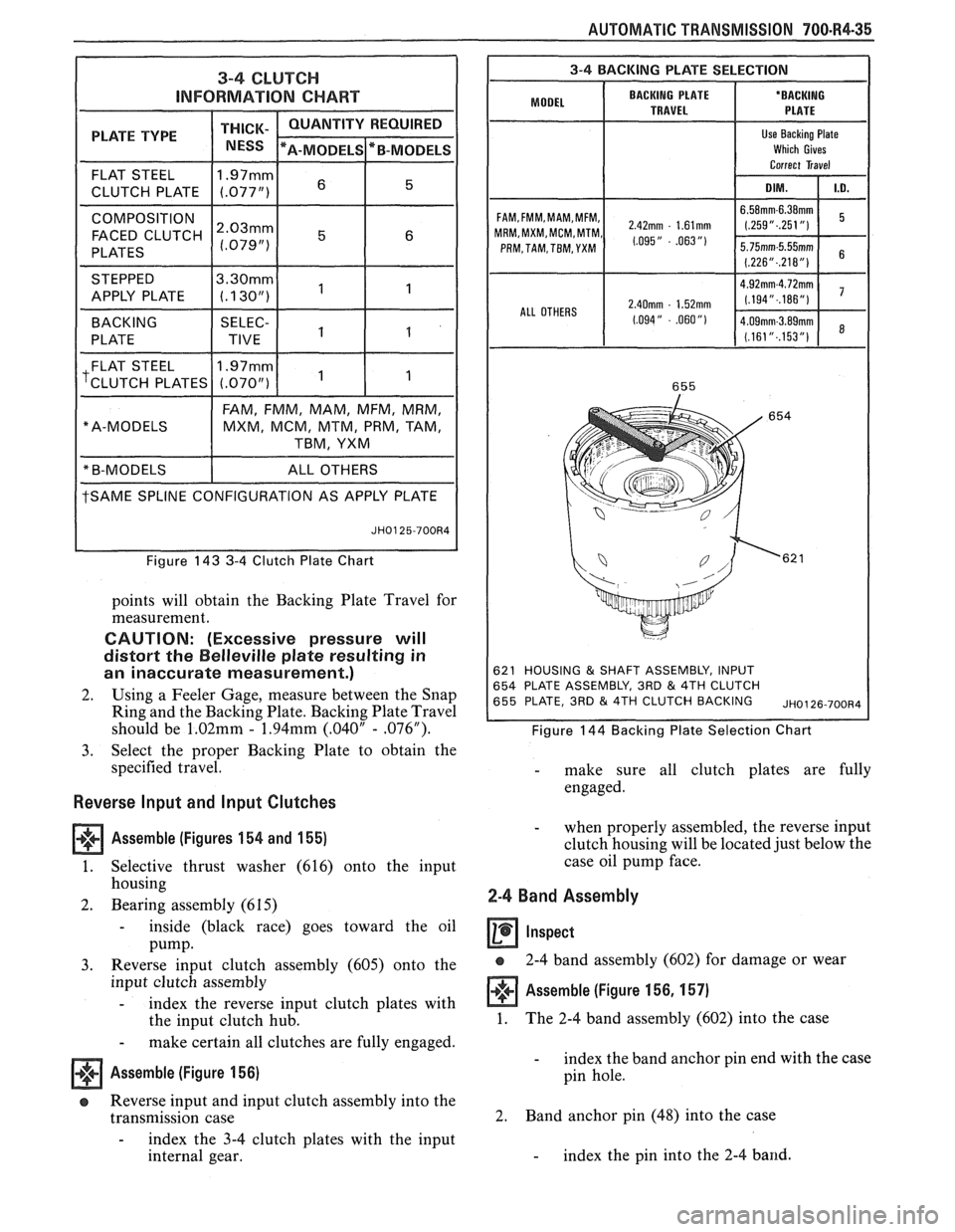
3-4 CLUTCH
INFORMATION CHART
PLATE TYPE THICK- / NESS
FLAT STEEL 11.97mml 6 15 1
CLUTCH
PLATE (.077")
COMPOSITION I 1 1 1
FACED CLUTCH ~:~~~~
PLATES
STEPPED
tSAME SPLINE CONFIGURATION AS APPLY PLATE
" A-MODELS
Figure 143 3-4 Clutch Plate Chart
FAM,
FMM, MAM, MFM, MRM,
MXM, MCM, MTM, PRM, TAM,
TBM, YXM
points will obtain the Backing Plate Travel for
measurement.
CAUTION: (Excessive pressure will
distort the
Belleville plate resulting in
an inaccurate measurement.)
2. Using a Feeler Gage, measure between the Snap
Ring and the Backing Plate. Backing Plate Travel
should be
1.02mm - 1.94mm (.040" - .076").
3. Select the proper Backing Plate to obtain the
specified travel.
Reverse lnput and Input Clutches
Assemble (Figures
154 and 155)
1. Selective thrust washer (616) onto the input
housing
2. Bearing assembly (6 15)
- inside (black race) goes toward the oil
Pump.
3. Reverse input clutch assembly (605) onto the
input clutch assembly
- index the reverse input clutch plates with
the input clutch hub.
- make certain all clutches are fully engaged.
Assemble (Figure 156)
a Reverse input and input clutch assembly into the
transmission case
- index the 3-4 clutch plates with the input
internal gear.
I 3-4 BACKING PLATE SELECTION I
BACKING PLATE
'ODE' I TRAVEL
FAM,FMM,MAM,MFM, 2,42mm . 1,61mm MRM,MXM,MCM,MTM, 1,095,, - .063 ,,, PRM, TAM, TBM, YXM
ALL OTHERS
2.40mm - 1.52mm
1.094" - .060")
621 HOUSING & SHAFT ASSEMBLY, INPUT
654 PLATE ASSEMBLY, 3RD & 4TH CLUTCH
655 PLATE, 3RD & 4TH CLUTCH BACKING ~~0126-700~4
Figure 144 Backing Plate Selection Chart
- make sure all clutch plates are fully
engaged.
- when properly assembled, the reverse input
clutch housing will be located just below the
case oil pump face.
2-4 Band Assembly
a 2-4 band assembly (602) for damage or wear
Assemble (Figure 156, 157)
1. The
2-4 band assembly (602) into the case
- index the band anchor pin end with the case
pin hole.
2. Band
anchor pin (48) into the case
- index the pin into the 2-4 band.
Page 1087 of 1825
700-R4-36 AUTOMATIC TRANSMISSION
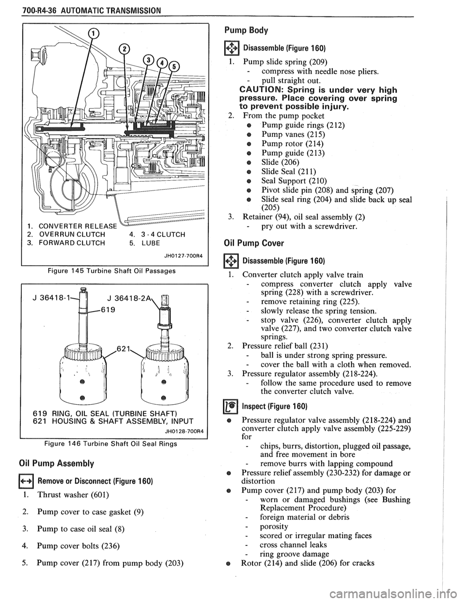
619 RING, OIL SEAL (TURBINE 621 HOUSING & SHAFT ASSE
JH0128-700R4
2. OVERRUN CLUTCH 4. 3 -4 CLUTCH
3. FORWARD CLUTCH
Figure
145 Turbine Shaft Oil Passages
Figure
146 Turbine Shaft Oil Seal Rings
Oil Pump Assembly
Remove or Disconnect (Figure 160)
1. Thrust washer (601)
2. Pump cover to case gasket (9)
3. Pump to case oil seal (8)
4. Pump cover bolts (236)
5. Pump cover (217) from pump body (203)
Pump Body
Disassemble (Figure 160)
1. Pump slide spring (209)
- compress with needle nose pliers.
- pull straight out.
CAUTION: Spring is under very high
pressure. Place covering over spring
to prevent possible injury.
2. From the pump pocket
e Pump guide rings (212)
Pump vanes (215)
e Pump rotor (214)
e Pump guide (213)
e Slide (206)
e Slide Seal (21 1)
e Seal Support (210)
e Pivot slide pin (208) and spring (207)
e Slide seal ring (204) and slide back up seal
(205)
3.
Retainer (94), oil seal assembly (2) - pry out with a screwdriver.
Oil Pump Cover
Disassemble (Figure 160)
1.
Converter clutch apply valve train
- compress converter clutch apply valve
spring (228) with a screwdriver.
- remove retaining ring (225). - slowly release the spring tension. - stop valve (226), converter clutch apply
valve
(227), and two converter clutch valve
springs.
2. Pressure relief ball (231)
- ball is under strong spring pressure. - cover the ball with a cloth when removed.
3. Pressure regulator assembly (2 18-224).
- follow the same procedure used to remove
the converter clutch valve.
Inspect (Figure 160)
e Pressure regulator valve assembly (2 18-224) and
converter clutch apply valve assembly (225-229)
for
- chips, burrs, distortion, plugged oil passage,
and free movement in bore
- remove burrs with lapping compound
e Pressure relief assembly (230-232) for damage or
distortion
e Pump cover (217) and pump body (203) for - worn or damaged bushings (see Bushing
Replacement Procedure)
- foreign material or debris
- porosity
- scored or irregular mating faces
- cross channel leaks
- ring groove damage
e Rotor (214) and slide (206) for cracks