1988 PONTIAC FIERO transmission oil
[x] Cancel search: transmission oilPage 1106 of 1825
AUTOMATIC TRANSMISSION 700-R4-55
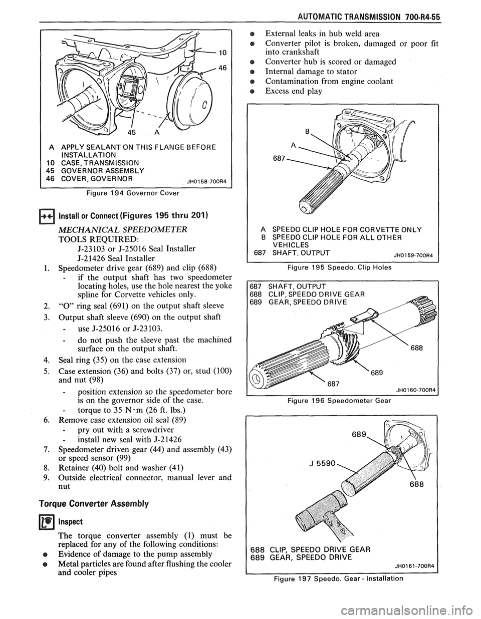
A APPLY SEALANT ON THIS FLANGE BEFORE
INSTALLATION
10 CASE TRANSMISSION
Figure
194 Governor Cover
Install or Connect (Figures 195 thru 201)
MECHANICAL SPEEDOMETER
TOOLS REQUIRED:
J-23 103 or J-25016 Seal Installer
J-21426 Seal Installer
1. Speedometer
drive gear (689) and clip (688)
- if the output shaft has two speedometer
locating holes, use the hole nearest the yoke
spline for Corvette vehicles only.
2. "0" ring seal (691) on the output shaft sleeve
3. Output shaft sleeve (690) on the output shaft
- use J-25016 or J-23103.
- do not push the sleeve past the machined
surface on the output shaft.
4. Seal
ring (35) on the case extension
5. Case extension
(36) and bolts
(37) or, stud (100)
and nut (98)
- position extension so the speedometer bore
is on the governor side of the case.
- torque to 35 N-m (26 ft. lbs.)
6. Remove case extension oil seal (89)
- pry out with a screwdriver
- install new seal with J-21426
7. Speedometer driven gear (44) and assembly (43)
or speed sensor (99)
8. Retainer (40) bolt and washer (41)
9. Outside
electrical connector, manual lever and
nut
Torque Converter Assembly
Inspect
The torque converter assembly (1) must be
replaced for any of the following conditions:
e Evidence of damage to the pump assembly
e Metal particles are found after flushing the cooler
and cooler pipes
a External leaks in hub weld area
e Converter pilot is broken, damaged or poor fit
into crankshaft
e Converter hub is scored or damaged
Internal damage to stator
e Contamination from engine coolant
a Excess end play
A SPEEDO CLlP HOLE FOR CORVETTE ONLY
B SPEEDO CLlP HOLE FOR ALL OTHER
VEHICLES
Figure
195 Speedo. Clip Holes
688 CLIP, SPEEDO DRIVE GEAR
689 GEAR, SPEEDO DRIVE
Figure 196 Speedometer Gear
688 CLIP, SPEEDO DRIVE GEAR
689 GEAR, SPEEDO DRIVE
Figure 197 Speedo. Gear
- Installation
Page 1107 of 1825
700-W4-56 AUTOMAT lC TRANSMISSION
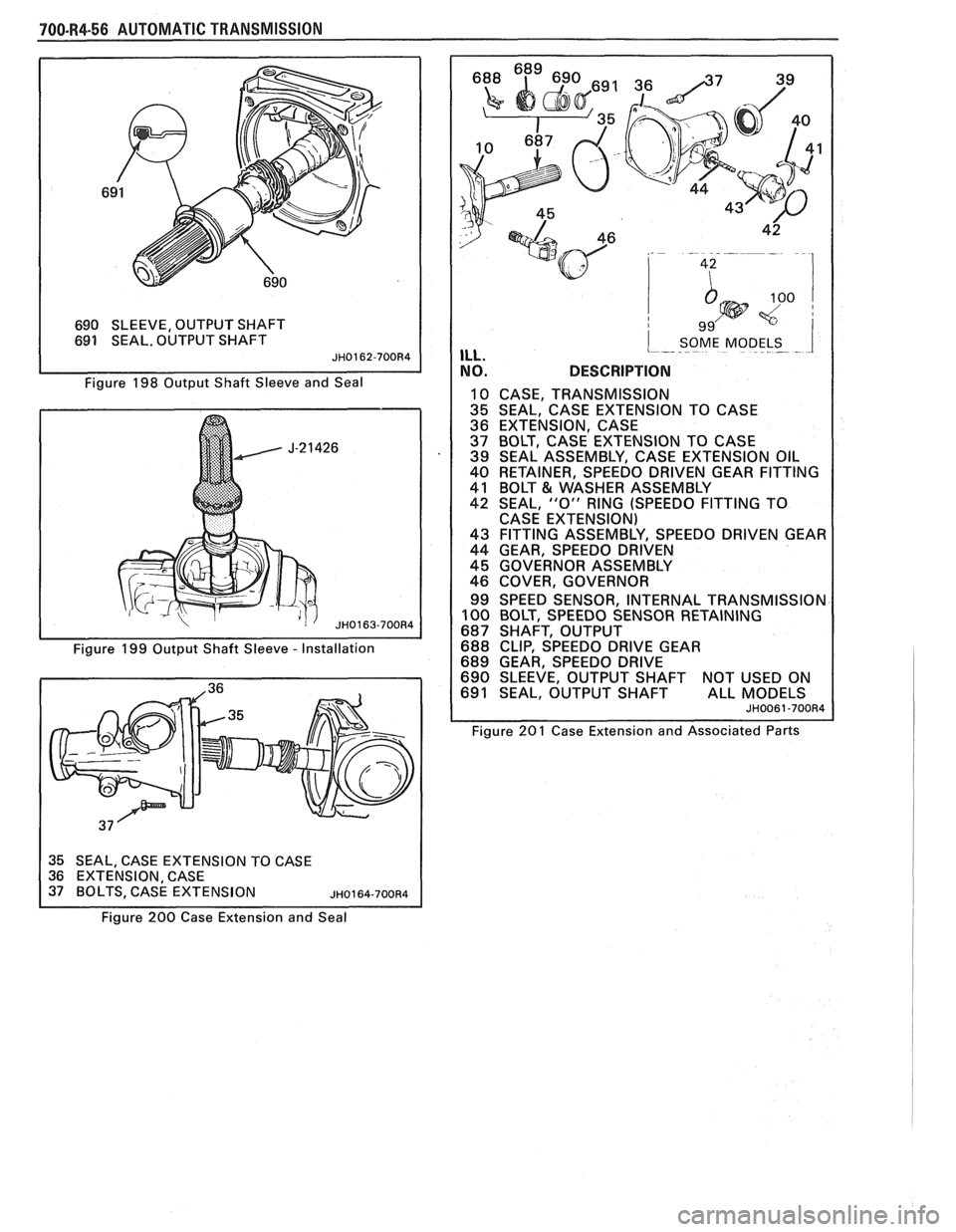
690 SLEEVE, OUTPUT SHAFT
691 SEAL. OUTPUT SHAFT
Figure 198 Output Shaft Sleeve and Seal
Figure 199 Output Shaft Sleeve
- Installation
35 SEAL, CASE EXTENSION TO CASE
36 EXTENSION CASE
9 9'
i SOME MODELS ILL. ----- - -- - 1
NO. DESCRIPTION
10 CASE, TRANSMISSION
35 SEAL, CASE EXTENSION TO CASE
36 EXTENSION, CASE
37 BOLT, CASE EXTENSION TO CASE
39 SEAL ASSEMBLY, CASE EXTENSION OIL
40 RETAINER, SPEEDO DRIVEN GEAR FITTING
41 BOLT
& WASHER ASSEMBLY
42 SEAL,
"0" RING (SPEEDO FITTING TO
CASE EXTENSION)
43 FITTING ASSEMBLY, SPEEDO DRIVEN GEAR
44 GEAR, SPEEDO DRIVEN
45 GOVERNOR ASSEMBLY
46 COVER, GOVERNOR
99 SPEED SENSOR, INTERNAL TRANSMISSION
100 BOLT, SPEEDO SENSOR RETAINING
687 SHAFT, OUTPUT
688 CLIP, SPEEDO DRIVE GEAR
689 GEAR, SPEEDO DRIVE
690 SLEEVE, OUTPUT SHAFT NOT USED ON
691 SEAL, OUTPUT SHAFT ALL MODELS
Figure 201 Case Extension and Associated Parts
Figure
200 Case Extension and Seal
Page 1108 of 1825
AUTOMATIC TRANSMISSION 700-R4-57
If:
e
Measure (Figure 203)
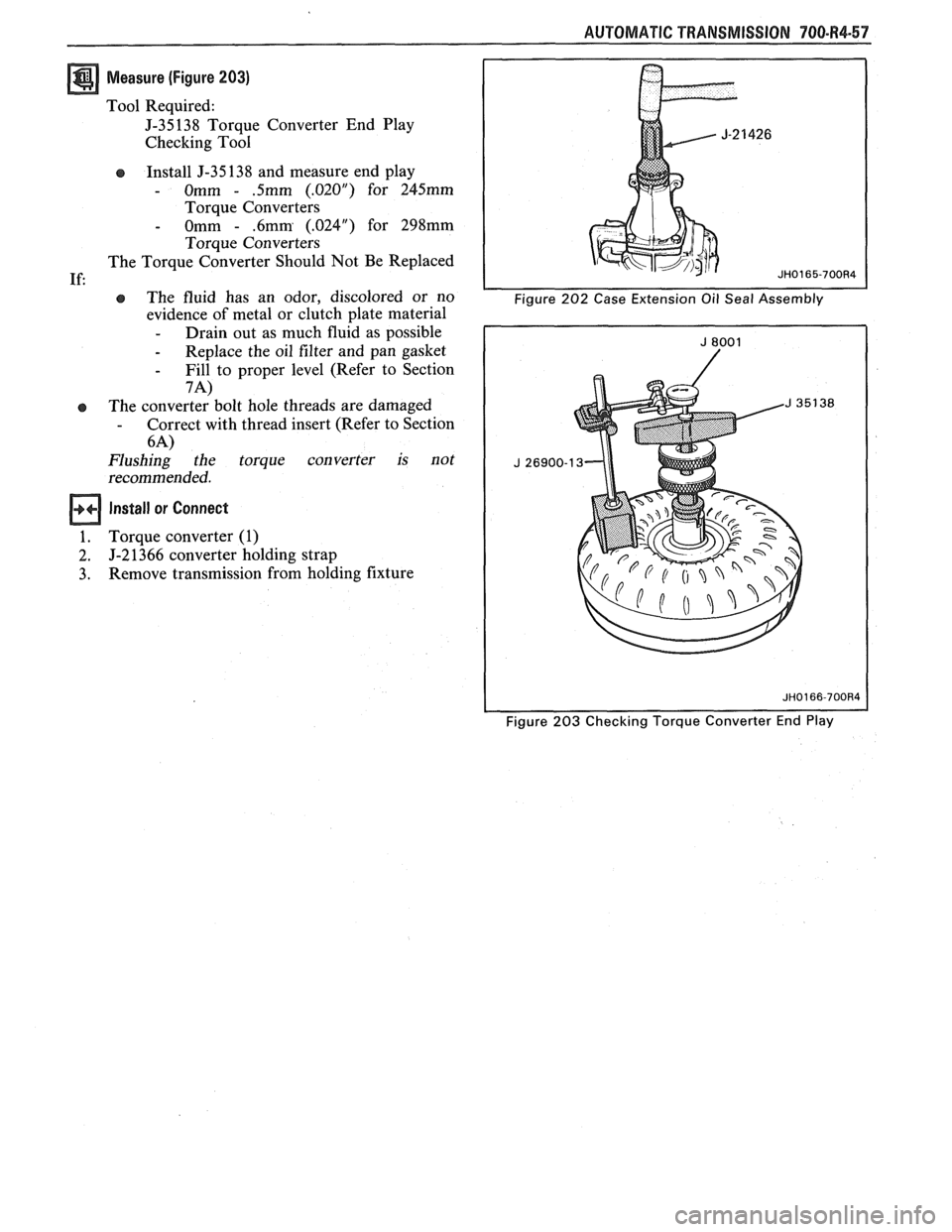
Tool Required:
J-35138 Torque Converter End Play
Checking Tool
Install J-35 138 and measure end play
- Omm - .5mm (.02OU) for 245mm
Torque Converters
- Omm - .6mm (.024") for 298mm
Torque Converters
The Torque Converter Should Not Be Replaced
e The fluid has an odor, discolored or no
evidence of metal or clutch plate material
- Drain out as much fluid as possible
- Replace the oil filter and pan gasket
- Fill to proper level (Refer to Section
7A)
The converter bolt hole threads are damaged - Correct with thread insert (Refer to Section
6-4)
Flushing the torque converter is not
recommended.
Install or Connect
Torque converter (1)
J-2 1366 converter holding strap
Remove transmission from holding fixture
Figure 203 Checking Torque Converter End Play
Page 1110 of 1825
AUTOMATIC TRANSMISSION 700.R4.59
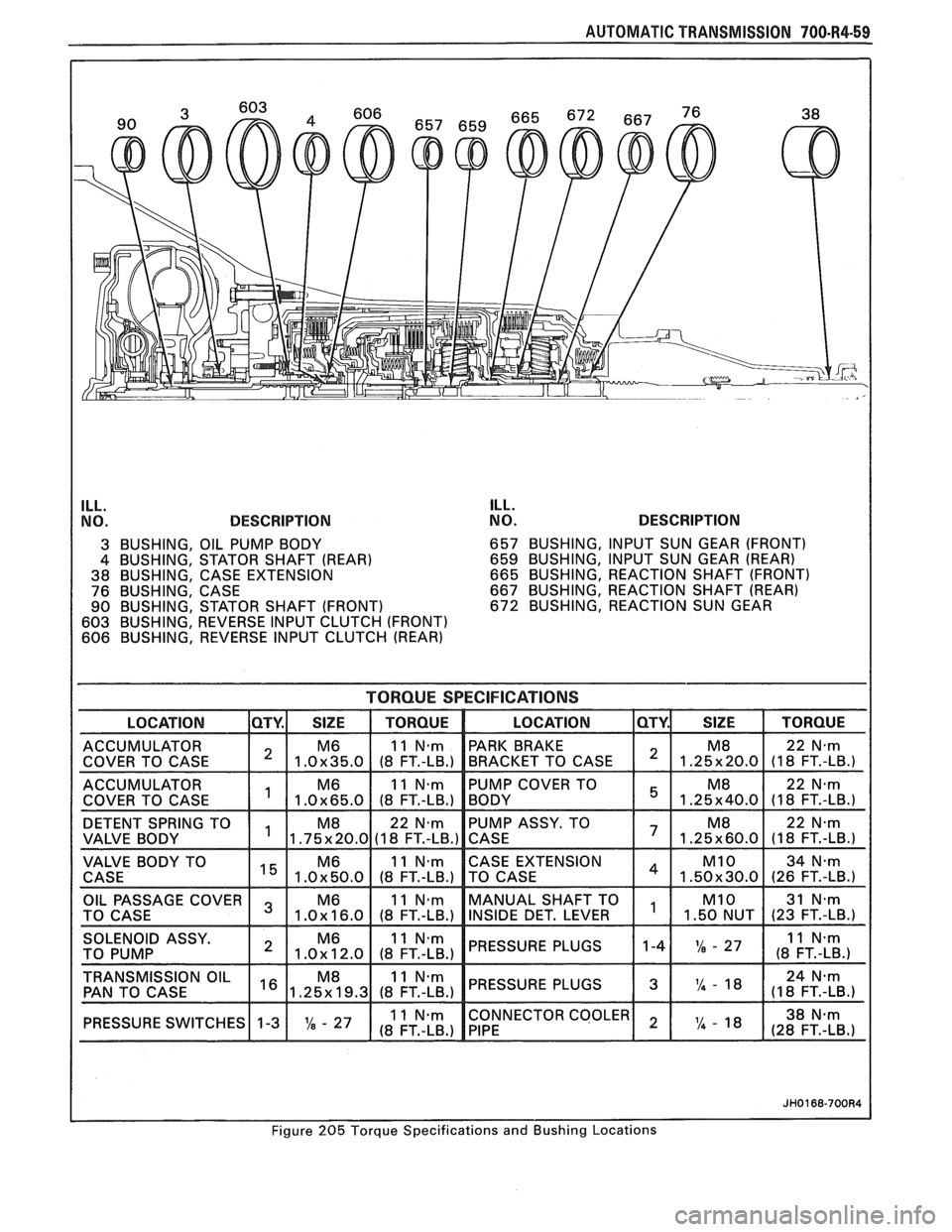
ILL.
NO. DESCRIPTION ILL.
NO. DESCRIPTION
3 BUSHING, OIL PUMP BODY 657
BUSHING, INPUT SUN GEAR (FRONT)
4 BUSHING, STATOR SHAFT (REAR) 659
BUSHING, INPUT SUN GEAR (REAR)
38 BUSHING, CASE EXTENSION 665
BUSHING, REACTION SHAFT (FRONT)
76 BUSHING, CASE 667
BUSHING, REACTION SHAFT (REAR)
90 BUSHING, STATOR SHAFT (FRONT) 672 BUSHING, REACTION SUN GEAR
603 BUSHING, REVERSE INPUT CLUTCH (FRONT)
606 BUSHING, REVERSE INPUT CLUTCH (REAR)
TORQUE SPECIFICATIONS
ACCUMULATOR 1 1 M6 I 11N.m COVER TO CASE 1.0~35.0 (8 FT.-LB.)
DETENT SPRING TO PUMP
ASSY. TO
CASE EXTENSION
PRESSURE PLUGS
TRANSMISSION OIL
PAN TO CASE PRESSURE
PLUGS
1 3 1 l4 - 8 1 (1 8 24 FT.-LB.) N'm
NECTOR COOLER
PRESSURE SWITCHES~ 1-3 1 X - 27 1
Figure 205 Torque Specifications and Bushing Locations
Page 1111 of 1825
700-R4-60 AUTOMATIC TRANSMISSION
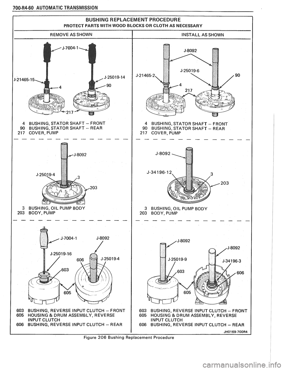
PROTECT PARTS WITH WOOD BLOCKS OR CLOTH AS NECESSARY
4 BUSHING, STATOR SHAFT - FRONT
90 BUSHING, STATOR
SHAFT
- REAR
217 COVER, PUMP 4 BUSHING, STATOR SHAFT - FRONT
90 BUSHING, STATOR SHAFT
- REAR
217 COVER, PUMP
3 BUSHING, OIL PUMP BODY
203 BODY, PUMP 3 BUSHING, OIL PUMP BODY
203 BODY, PUMP
603 BUSHING, REVERSE INPUT CLUTCH
- FRONT
605
HOUSlNG&DRUMASSEMBLY, REVERSE
INPUT CLUTCH
606 BUSHING, REVERSE INPUT CLUTCH
- REAR 603
BUSHING, REVERSE INPUT CLUTCH
- FRONT
605 HOUSING & DRUM ASSEMBLY, REVERSE
INPUT CLUTCH
606 BUSHING, REVERSE INPUT CLUTCH
- REAR
Figure 206 Bushing Replacement Procedure
Page 1114 of 1825
AUTOMATIC TRANSMISSION 700-R4-63
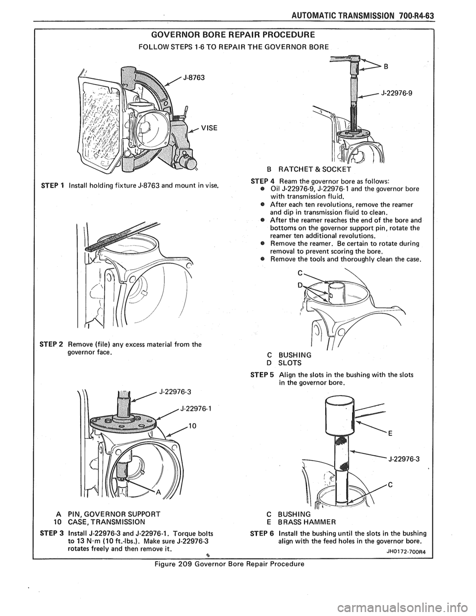
GOVERNOR BORE REPAIR PROCEDURE
FOLLOW STEPS 1-6 TO REPAIR THE GOVERNOR BORE
STEP
1 Install holding fixture J-8763 and mount in vise.
STEP
2 Remove (file) any excess material from the
governor face.
B RATCHET & SOCKET
STEP
4 Ream the governor bore as follows: @ Oil J-22976-9, J-22976-1 and the governor bore
with transmission fluid.
@ After each ten revolutions, remove the reamer
and dip in transmission fluid to clean.
@ After the reamer reaches the end of the bore and
bottoms on the governor support pin, rotate the
reamer ten additional revolutions.
Remove the reamer. Be certain to rotate during
removal to prevent scoring the bore.
Remove the tools and thoroughly clean the case.
C
C BUSHING
D SLOTS
STEP
5 Align the slots in the bushing with the slots
in the governor bore.
A PIN, GOVERNOR SUPPORT
10 CASE, TRANSMISSION
STEP
3 Install J-22976-3 and J-22976-1. Torque bolts
to 13 N.m (10 ft.-lbs.). Make sure J-22976-3
rotates freely and then remove it. *
C BUSHING
E BRASS HAMMER
STEP
6 Install the bushing until the slots in the bushing
align with the feed holes in the governor bore.
Figure 209 Governor Bore Repair Procedure
Page 1115 of 1825
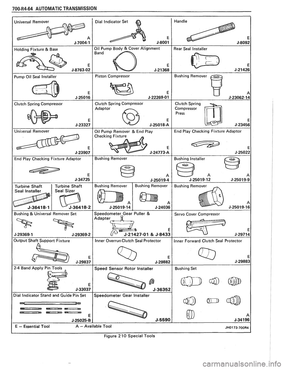
780-R4-64 AUTOMATIC TRANSMISSION
-
Universal Remover Dial Indicator Set
I - -
1 Pump Oil Seal Installer I Piston Compressor 1 Bushing Remover I
Clutch Spring Compressor Clutch Spring
Compressor
J-25022
End Play Checking Fixture Adaptor Bushing
Remover
Figure
2 10 Special Tools
Page 1117 of 1825
7A-2 AUTOMATIC TRANSMISSION
I I
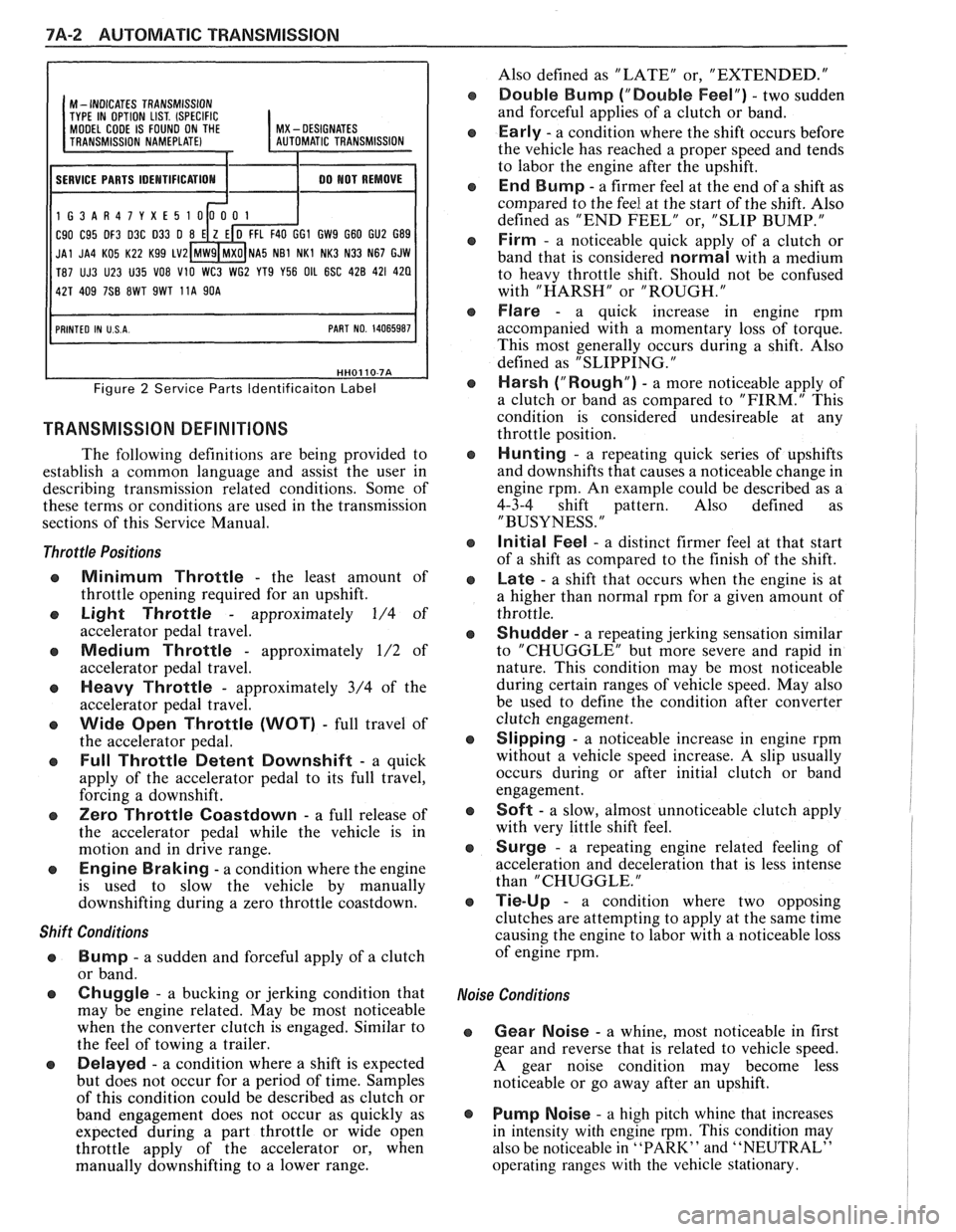
M - INDICATES TRANSMISSION
TYPE IN OPTION LIST. (SPECIFIC MODEL CODE IS FOUND ON THE I MX - DESIGNATES
11 SERVICE PARTS IDEMTIFICATIOM I 1 00 MOT REMOVE I
1G3AR47YXE5
C90 C95 DF3 D3C 033 0 GI GW9 G60 GU2 G89
JAl JA4 KO5 K22 Kg9 LV2 NA5 NB1 NKl NK3 N33 N67 GJW
T87 UJ3 U23 U35
VO8 V10 WC3 WG2 YT9 Y56 OIL 6SC 428 421 420
Figure 2 Service Parts ldentificaiton Label
TRANSMISSION DEFINITIONS
The following definitions are being provided to
establish a common language and assist the user in
describing transmission related conditions. Some of
these terms or conditions are used in the transmission
sections of this Service Manual.
Throttle Positions
Minimum Throttle - the least amount of
throttle opening required for an upshift.
Light Throttle - approximately 1/4 of
accelerator pedal travel.
Medium Throttle - approximately 1/2 of
accelerator pedal travel.
Heavy Throttle - approximately 3/4 of the
accelerator pedal travel.
Wide Open Throttle (WOT) - full travel of
the accelerator pedal.
Full Throttle Detent Downshift - a quick
apply of the accelerator pedal to its full travel,
forcing a downshift.
Zero Throttle Coastdown - a full release of
the accelerator pedal while the vehicle is in
motion and in drive range.
Engine Braking - a condition where the engine
is used to slow the vehicle by manually
downshifting during a zero throttle coastdown.
Shift Conditions
'a Bump - a sudden and forceful apply of a clutch
or band.
Q Chuggle - a bucking or jerking condition that
may be engine related. May be most noticeable
when the converter clutch is engaged. Similar to
the feel of towing a trailer.
e Delayed - a condition where a shift is expected
but does not occur for a period of time. Samples
of this condition could be described as clutch or
band engagement does not occur as quickly as
expected during a part throttle or wide open
throttle apply of the accelerator or, when
manually downshifting to a lower range. Also
defined as "LATE" or, "EXTENDED."
Double Bump ("Double Feel") - two sudden
and forceful applies of a clutch or band.
Early - a condition where the shift occurs before
the vehicle has reached a proper speed and tends
to labor the engine after the upshift.
End Bump - a firmer feel at the end of a shift as
compared to the feel at the start of the shift. Also
defined as "END FEEL" or, "SLIP BUMP."
Firm - a noticeable quick apply of a clutch or
band that is considered
normal with a medium
to heavy throttle shift. Should not be confused
with "HARSH" or "ROUGH."
Flare - a quick increase in engine rpm
accompanied with a momentary loss of torque.
This most generally occurs during a shift. Also
defined as "SLIPPING.
"
Harsh ("Rough") - a more noticeable apply of
a clutch or band as compared to "FIRM." This
condition is considered undesireable at any
throttle position.
Hunting - a repeating quick series of upshifts
and downshifts that causes a noticeable change in
engine rpm. An example could be described as a
4-3-4 shift pattern. Also defined as
"BUSYNESS.
"
Initial Feel - a distinct firmer feel at that start
of a shift as compared to the finish of the shift.
Late - a shift that occurs when the engine is at
a higher than normal rpm for a given amount of
throttle.
Shudder - a repeating jerking sensation similar
to "CHUGGLE" but more severe and rapid in
nature. This condition may be most noticeable
during certain ranges of vehicle speed. May also
be used to define the condition after converter
clutch engagement.
Slipping - a noticeable increase in engine rpm
without a vehicle speed increase.
A slip usually
occurs during or after initial clutch or band
engagement.
Soft - a slow, almost unnoticeable clutch apply
with very little shift feel.
Surge - a repeating engine related feeling of
acceleration and deceleration that is less intense
than "CHUGGLE.
"
Tie-Up - a condition where two opposing
clutches are attempting to apply at the same time
causing the engine to labor with a noticeable loss
of engine rpm.
,e Conditions
Gear Noise - a whine, most noticeable in first
gear and reverse that is related to vehicle speed.
A gear noise condition may become less
noticeable or go away after an upshift.
Pump Noise - a high pitch whine that increases
in intensity with engine
rpm. This condition may
also be noticeable in
"PARK" and "NEUTRAL"
operating ranges with the vehicle stationary.