1988 PONTIAC FIERO transmission oil
[x] Cancel search: transmission oilPage 1144 of 1825
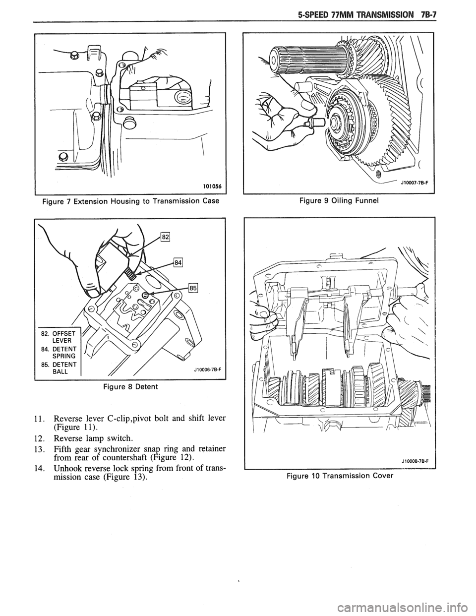
Figure 7 Extension Housing to Transmission Case Figure 9 Oiling
Funnel
Figure
8 Detent
11. Reverse lever C-clip,pivot bolt and shift lever
(Figure
1 I).
12. Reverse lamp switch.
13. Fifth gear synchronizer snap ring and retainer
from rear of countershaft (Figure
12).
14. Unhook reverse lock spring from front of trans-
mission case (Figure
13). Figure 10 Transmission Cover
Page 1150 of 1825
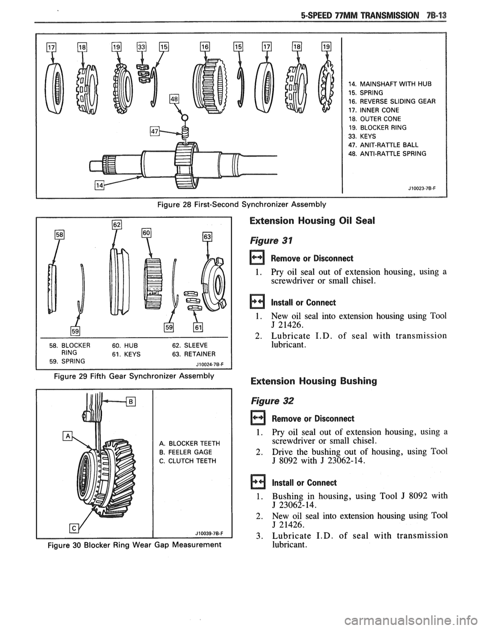
14. MAINSHAFT WITH HUB
15. SPRING
16. REVERSE SLIDING GEAR
17, INNER CONE
18. OUTER CONE
19. BLOCKER RING
33. KEYS
47.
ANIT-RAlTLE BALL
48. ANTI-RATTLE SPRING
Figure 28 First-Second Synchronizer Assembly
63. RETAINER
Figure 29 Fifth Gear Synchronizer Assembly
Extension Housing Oil Seal
Figure 31
Remove or Disconnect
1. Pry oil seal
out of extension housing, using a
screwdriver or small chisel.
Install or Connect
1. New oil seal into extension housing using Tool
J 21426.
2. Lubricate
I.D. of seal with transmission
lubricant.
Extension Housing Bushing
A. BLOCKER TEETH
B. FEELER GAGE
C. CLUTCH TEETH
Figure 32
rn Remove or Disconned
1. Pry oil seal out of extension housing, using a
screwdriver or small chisel.
2. Drive the bushing
out of housing, using Tool
J 8092 with J 23062-14.
Install or Connect
1. Bushing in housing, using Tool J 8092 with
J 23062-14.
2. New
oil seal into extension housing using
Tm1
J 21426.
3. Lubricate
I.D. of seal with transmission
Figure 30 Blocker Ring Wear Gap Measurement lubricant.
Page 1151 of 1825
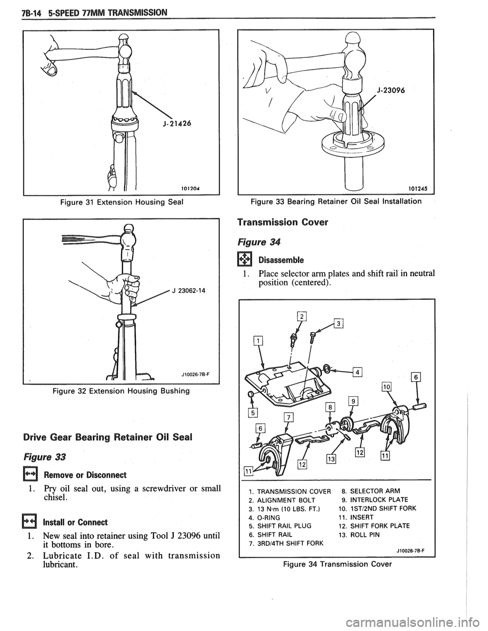
Figure 31 Extension Housing Seal
Figure
32 Extension Housing Bushing
Drive Gear Bearing Retainer Oil Seal
Figure 33
Remove or Disconnect
1. Pry oil seal out, using a screwdriver or small
chisel.
Install or Connect
1. New seal into retainer using Tool J 23096 until
it bottoms in bore.
2. Lubricate I.D. of seal with transmission
lubricant.
Figure 33 Bearing Retainer Oil Seal Installation
Transmission Cover
Figure 34
Disassemble
1. Place selector am plates and shift rail in neutral
position (centered).
1. TRANSMISSION COVER 8. SELECTOR ARM
2. ALIGNMENT BOLT
9. INTERLOCK PLATE
3. 13
Nm (10 LBS. FT.) 10. 1STI2ND SHlFT
FORK
11. INSERT
5. SHIFT RAIL PLUG 12. SHIFT FORK PLATE
6. SHIFT RAIL 13. ROLL PIN
7. 3RDl4TH SHlFT FORK
Figure 34 Transmission Cover
Page 1155 of 1825
78-18 5-SPEED 77MM TRANSMISSION
Blocker ring and fifth gear synchronizer in fifth
gear shift fork. Slide fork rail assembly and syn-
chronizer into position. (Figure 20)
Fifth gear synchronizer retainer and snap ring
(Figure 12).
Oiling funnel into rear of countershaft (Figure
9)
Position fifthlreverse shift lever in case.
Connect lever return spring to front of case.
Make sure reverse shift fork pin and fifth gear
shift rail pin are engaged with shift lever and
install fifth
gearlreverse lever, pivot bolt and
retaining clip. Coat pivot bolt threads with pipe
thread sealant
#lo52080 or equivalent.
Reverse lamp switch. Coat threads with pipe
thread sealant
# 1052080 or equivalent.
Speedometer gear and retaining clip.
Circlip.
Apply 3mm
(118in.) bead of RTV Sealant,
# 105275 1 or equivalent, to transmission cover
assembly.
Make sure all synchronizers are in the neutral
position and that the shift forks in the cover are
in the neutral (center) position. Lower cover
onto case while aligning shift forks and synchro-
nizer sleeves.
Center cover and install two dowel bolts.
Remaining cover bolts.
Tighten
@ Torque all cover bolts to 14 N*m (10 lbs.
ft.).
Apply 3mm (118 in.) bead of RTV Sealant,
#I05275 1 or equivalent, to extension housing
mating surface.
Coat detent spring with petroleum jelly and
insert in offset lever. Lubricate detent plate and
install detent ball in neutral position on plate.
Position offset lever in extension housing with
spring over detent ball. Slide lever and exten-
sion housing into position as an assembly.
Extension housing vent.
Press downward on offset lever to compress
detent spring and push lever and housing into
position.
Extension housing bolts. Apply pipe thread
sealant
#lo52080 or equivalent to threads of
top two bolts.
Tighten
@ Torque extension housing bolts to 30 Nm
(23 lbs. ft.)
Align and install roll pin in offset lever and shift
rail. 35. Damper
sleeve in offset lever.
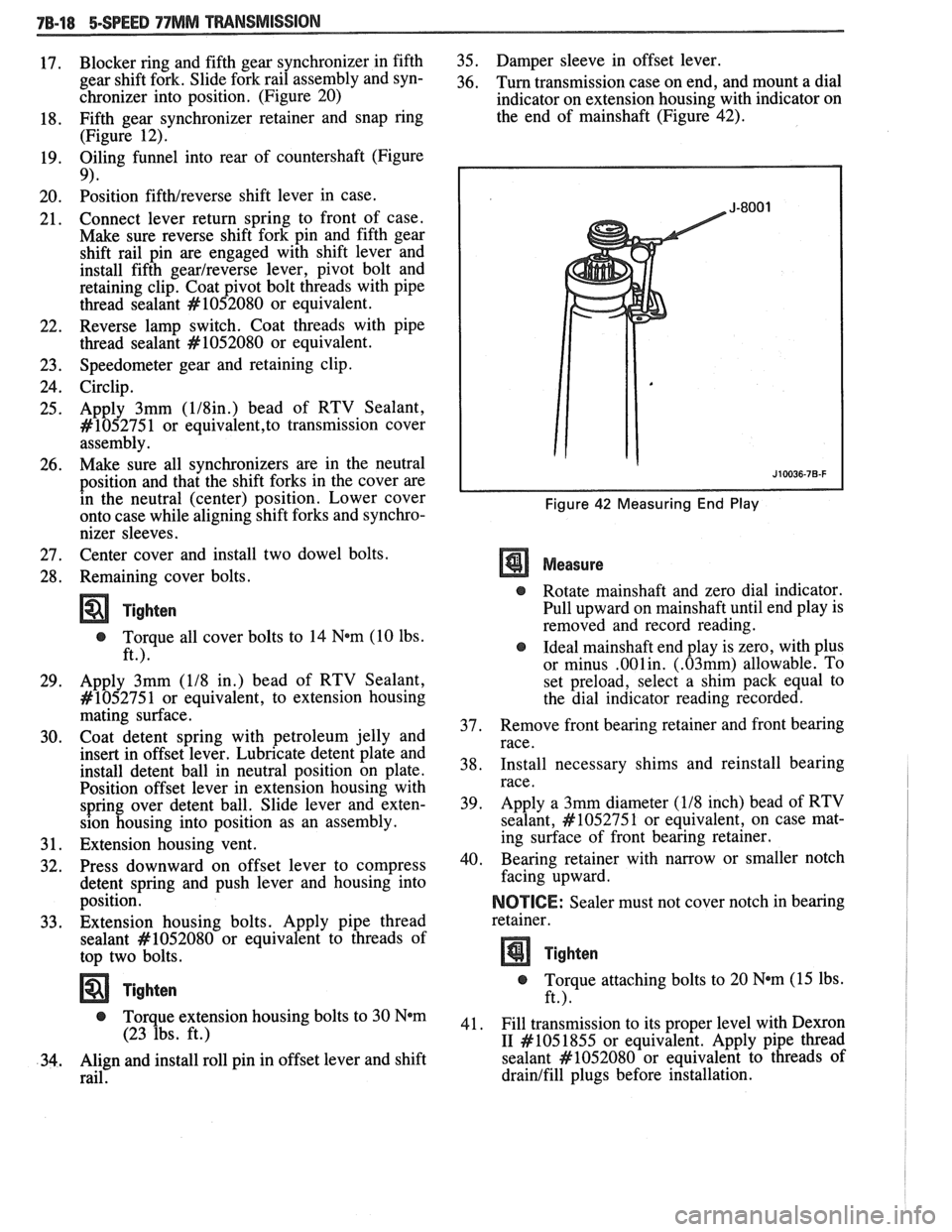
36. Turn transmission case on end, and mount a dial
indicator on extension housing with indicator on
the end of mainshaft (Figure 42).
Figure 42 Measuring End Play
Measure
@ Rotate mainshaft and zero dial indicator.
Pull upward on mainshaft until end play is
removed and record reading.
@ Ideal mainshaft end play is zero, with plus
or minus
.001in. (.03mm) allowable. To
set preload, select a shim pack equal to
the dial indicator reading recorded.
37. Remove
front bearing retainer and front bearing
race.
38. Install
necessary shims and reinstall bearing
race.
39. Apply
a 3mm diameter
(118 inch) bead of RTV
sealant,
#lo5275 1 or equivalent, on case mat-
ing surface of front bearing retainer.
40. Bearing retainer with narrow
or smaller notch
facing upward.
NOICE: Sealer must not cover notch in bearing
retainer.
Tighten
@ Torque attaching bolts to 20 N*m (15 lbs.
ft.).
41. Fill transmission to its proper level with
Dexron
I1 #I05 1855
or equivalent. Apply pipe thread
sealant
#lo52080 or equivalent to threads of
drainlfill plugs before installation.
Page 1162 of 1825
CLUTCH 7C-5
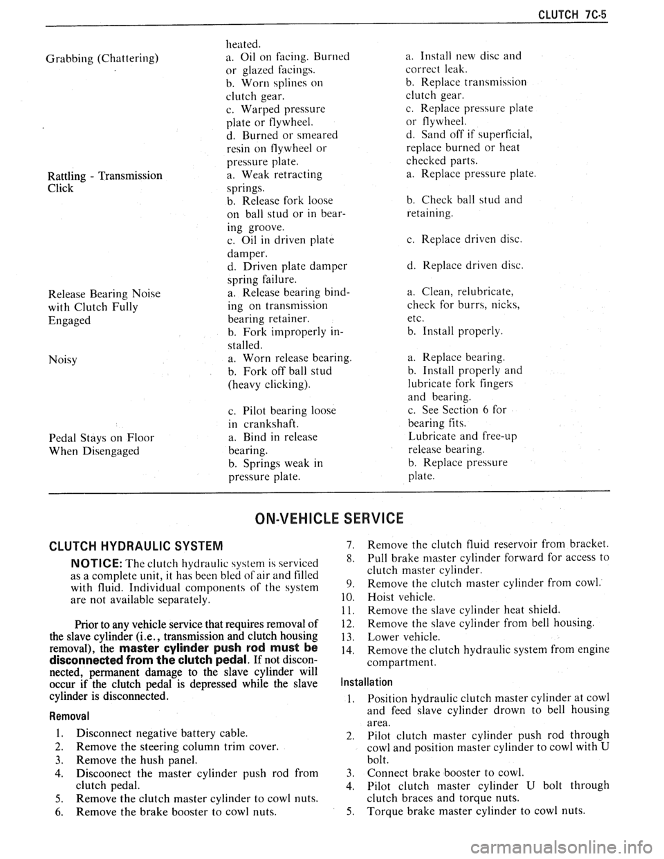
Grabbing (Chattering)
Rattling
- Transmission
Click
Release Bearing Noise
with Clutch Fully
Engaged
Noisy
Pedal Stays on Floor
When Disengaged heated.
a. Oil
on facing. Burned
or glazed facings.
b. Worn splines
on
clutch gear.
c. Warped pressure
plate or flywheel.
d. Burned or smeared
resin on flywheel or
pressure plate.
a. Weak retracting
springs.
b. Release fork loose
on ball stud or in bear-
ing groove.
c. Oil in driven plate
damper.
d. Driven plate damper
spring failure.
a. Release bearing bind-
ing on transmission
bearing retainer.
b. Fork improperly in-
stalled. a. Worn release bearing.
b. Fork off ball stud
(heavy clicking).
c. Pilot bearing loose
in crankshaft.
a. Bind in release
bearing.
b. Springs weak in
pressure plate. a.
Install new disc and
correct leak.
b. Replace transmission
clutch gear.
c. Replace pressure plate
or flywheel.
d. Sand off if superficial,
replace burned or heat
checked parts.
a. Replace pressure plate.
b. Check ball stud and
retaining.
c. Replace driven disc.
d. Replace driven disc.
a. Clean, relubricate,
check for burrs, nicks,
etc.
b. Install properly.
a. Replace bearing.
b. Install properly and
lubricate fork fingers
and bearing.
c. See Section
6 for
bearing fits.
Lubricate and free-up
release bearing.
b. Replace pressure
plate.
ON-VEHICLE SERVICE
CLUTCH HYDRAULIC SYSTEM 7. Remove the clutch fluid reservoir from bracket.
NOTICE: The clutch hydraul~c 4ystern is serviced 8. Pull brake niaster cylinder forward for access to
as a complete unit, it has been bled
of air and filled clutch master cylinder.
with fluid. Individual components of the system 9. Remove the clutch master cylinder from cowl.
are
not available separately. 10. Hoist vehicle.
1 1. Remove the slave cvlinder heat shield.
Prior to any vehicle service that requires removal of
the slave cylinder
(i.e., transmission and clutch housing
removal), the
master cylinder push rod must be
disconnected from the clutch pedal. If not discon-
nected, permanent damage to the slave cylinder will
occur if the clutch pedal is depressed while the slave
cylinder is disconnected.
Removal
1. Disconnect negative battery cable.
2. Remove the steering column trim cover.
3. Remove the hush panel.
4. Discoonect the master cylinder push rod from
clutch pedal.
5. Remove the clutch master cylinder to cowl nuts.
6. Remove the brake booster to cowl nuts.
12. Remove the slave cylinder from bell housing.
13. Lower vehicle.
14. Remove the clutch hydraulic system from engine
compartment.
Installation
1. Position
hydraulic clutch master cylinder at cowl
and feed slave cylinder drown to bell housing
area.
2. Pilot clutch master cylinder push rod through
cowl and position master cylinder to cowl with
U
bolt.
3. Connect brake booster to cowl.
4. Pilot clutch master cylinder
U bolt through
clutch braces and torque nuts.
5. Torque brake master cylinder to cowl nuts.
Page 1163 of 1825
7C-6 CLUTCH
6. Clutch master cylinder push rod to clutch pedal.
7. Install brake switch.
8. Install hush panel.
9. Install steering column trim cover.
10. Install clutch reservoir to bracket.
1 1. Hoist vehicle.
12. Pilot slave cylinder into clutch fork.
NOTICE: With a new system, the slave cylinder
contains a shipping strap that pre-positions the
push rod for installation, and also provides a
bearing insert.
Follojving installation of the slave
cylinder, the first actuation of the clutch pedal will
break the shipping strap and give
normal system
operation.
13. Install slave cylinder and heat shield to bell
housing.
14.
Lojver vehicle.
15. Connect negative battery cable.
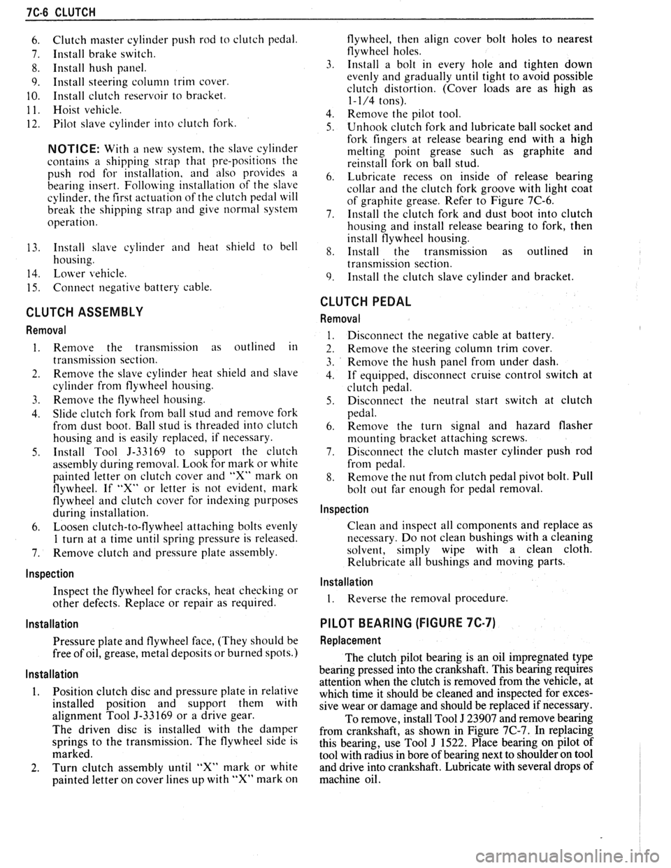
CLUTCH ASSEMBLY
Removal
1. Remove the transmission as outlined in
transmission section.
2. Remove the slave cylinder heat shield and slave
cylinder
from flywheel housing.
3. Reniove the flywheel housing.
4. Slide clutch fork from ball stud and remove fork
from dust boot. Ball stud is threaded into clutch
housing and is easily replaced, if necessary.
5. Install Tool 5-33169 to support the clutch
assen~bly during removal. Look for mark or white
painted letter on clutch cover and
"X" mark on
flywheel. If
"Xu or letter is not evident, mark
flywheel and clutch cover for indexing purposes
during installation.
6. Loosen clutch-to-flywheel attaching bolts evenly
1 turn at a time until spring pressure is released.
7. Remove clutch and pressure plate assembly.
lnspection
Inspect the flywheel for cracks, heat checking or
other defects. Replace or repair as required.
Installation
Pressure plate and flywheel face, (They should be
free of oil, grease, metal deposits or burned spots.)
Installation
1. Position clutch disc and pressure plate in relative
installed position and support them with
alignment Tool J-33169 or a drive gear.
The driven disc is installed with the damper
springs to the transmission. The flywheel side is
marked.
2. Turn clutch assembly until "X" mark or white
painted letter on cover lines up with
"X" mark on flywheel,
then align cover bolt holes to nearest
flywheel holes.
3. Install a bolt in every hole and tighten down
evenly and gradually until tight to avoid possible
clutch distortion. (Cover loads are as high as
1- 1/4 tons).
4. Remove the pilot tool.
5. Unhook clutch fork and lubricate ball socket and
fork fingers at release bearing end with a high
melting point grease such as graphite and
reinstall fork on ball stud.
6. Lubricate recess on inside of release bearing
collar and the clutch fork groove with light coat
of graphite grease. Refer to Figure 7C-6.
7. Install the clutch fork and dust boot into clutch
housing and install release bearing to fork, then
install flywheel housing.
8. Install the transmission as outlined in
transmission section.
9. Install the clutch slave cylinder and bracket.
CLUTCH PEDAL
Removal
Disconnect the negative cable at battery.
Remove the steering column trim cover.
Remove the hush panel from under dash.
If equipped, disconnect cruise control switch at
clutch pedal.
Disconnect the neutral start switch at clutch
pedal.
Renlove the turn signal and hazard flasher
mounting bracket attaching screws.
Disconnect the clutch master cylinder push rod
from pedal.
Remove the nut from clutch pedal pivot bolt. Pull
bolt out far enough for pedal removal.
Inspection
Clean and inspect all components and replace as
necessary. Do not clean bushings with a cleaning
solvent, simply wipe with a clean cloth.
Relubricate all bushings and moving parts.
Installation
1. Reverse the removal procedure.
PILOT BEARING (FIGURE 7C-7)
Replacement
The clutch pilot bearing is an oil impregnated type
bearing pressed into the crankshaft. This bearing requires
attention when the clutch is removed from the vehicle, at
which time it should be cleaned and inspected for exces-
sive wear or damage and should be replaced if necessary.
To remove, install Tool
J 23907 and remove bearing
from crankshaft, as shown in Figure
7C-7. In replacing
this bearing, use Tool
J 1522. Place bearing on pilot of
tool with radius in bore of bearing next to shoulder on tool
and drive into crankshaft. Lubricate with several drops of
machine oil.
Page 1320 of 1825
VEHICLE SPEED SENSOR
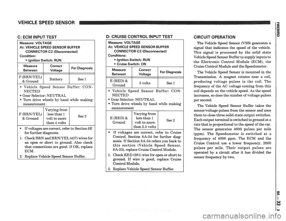
C: ECM INPUT TEST
At: VEHICLE SPEED SENSOR BUFFER
CONNECTOR
62 (Disconnected)
Gear Selector: NEUTRAL
1. Check BRN and
BRNIYEL (437) wires for
an open or short to ground. Also check
that connections are good. If
OK, replace
1 2. Replace Vehicle Speed Sensor Buffer.
At: VEHICLE SPEED SENSOR BUFFER
CONNECTOR
C2 (Disconnected)
Gear Selector: NEUTRAL
nosis. If Section 8A-34 refers you back to
this section (Vehicle Speed Sensor,
8A-33), replace Cruise Control Module.
1. Check RED (381) wire for open or short to
ground. If wire is good, replace Cruise
Control Module.
D: CRUISE CONTROL lNPUT TEST CIRCUIT OPERATION
The Vehicle Speed Sensor (VSS) generates a
signal that indicates the speed of the vehicle.
This signal is processed by the solid state
Vehicle Speed Sensor Buffer to supply inputs to
the Electronic Control Module (ECM), the
Cruise Control Module
and the Speedometer.
The Vehicle Speed Sensor is mounted in the
Transmission.
A magnet rotates near a coil,
producing voltage pulses in the coil. The
frequency of the AC voltage coming from this
coil depends on the vehicle speed. As the speed
increases, so does the number of voltage pulses
per second.
The Vehicle Speed Sensor Buffer takes the
sensorlvoltage pulses from the sensor and uses
them to close three solid state output switches.
Each output terminal is switched to ground at a
rate that is proportional to the speed of the car.
The sensor generates 4000 pulses per mile
(ppm). The Speedometer is switched at
a
frequency of 4000 ppm. The ECM and the
Cruise Control use a lower frequency, 2000
pulses per mile. Their output pulses are
operated by a circuit after it has divided the
sensor frequency by two.
Page 1327 of 1825
CRUISE CONTROL
(Continued from previous page)
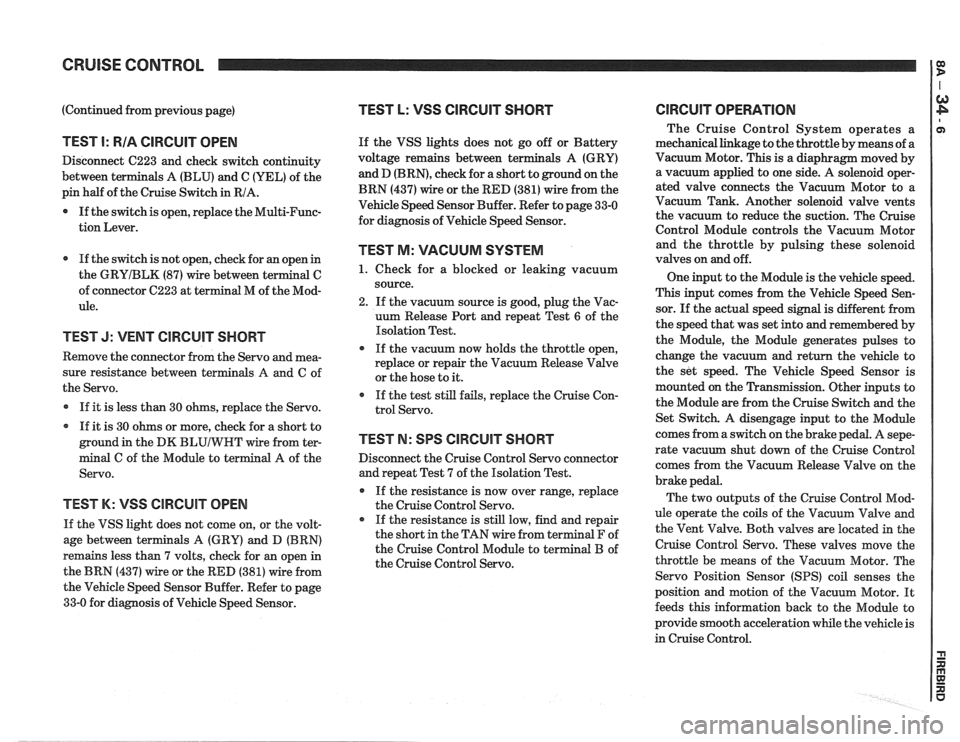
TEST I: RIA CIRCUIT OPEN
Disconnect C223 and check switch continuity
between terminals A (BLU) and C (YEL) of the
pin half of the Cruise Switch in RIA.
0 If the switch is open, replace the Multi-Func-
tion Lever.
If the switch is not open, check for an open in
the
GRYIBLK (87) wire between terminal C
of connector C223 at terminal M of the Mod-
ule.
TEST J: VENT CIRCUIT SHORT
Remove the connector from the Servo and mea-
sure resistance between terminals
A and C of
the Servo.
If it is less than 30 ohms, replace the Servo.
If it is 30 ohms or more, check for a short to
ground in the DK
BLUIWHT wire from ter-
minal C of the Module to terminal A of the
Servo.
TEST K: VSS ClRCUlT OPEN
If the VSS light does not come on, or the volt-
age between terminals A (GRY) and D (BRN)
remains less than 7 volts, check for an open in
the BRN (437) wire or the RED (381) wire from
the Vehicle Speed Sensor Buffer. Refer to page
33-0 for diagnosis of Vehicle Speed Sensor.
TEST L: VSS CIRCUIT SHORT
If the VSS lights does not go off or Battery
voltage remains between ter
and D
(BRN), check for a short to ground on the
BRN (437) wire or the RED (381) wire from the
Vehicle Speed Sensor Buffer. Refer to page 33-0
for diagnosis of Vehicle Speed Sensor.
TEST M: VACUUM SYSTEM
1. Check for a blocked or leaking vacuum
source.
2. If the vacuum source is good, plug the Vac-
uum Release Port and repeat Test
6 of the
Isolation Test.
If the vacuum now holds the throttle open,
replace or repair the Vacuum Release Valve
or the hose to it.
If the test still fails, replace the Cruise Con-
trol Servo.
TEST N: SPS CIRCUIT SHORT
Disconnect the Cruise Control Servo connector
and repeat Test 7 of the Isolation Test.
If the resistance is now over range, replace
the Cruise Control Servo.
If the resistance is still low, find and repair
the short in the TAN wire from terminal F of
the Cruise Control Module to terminal B of
the Cruise Control Servo.
ClRCUlT OPERATION
The Cruise Control System operates a
mechanical linkage to the throttle by means of a
Vacuum Motor. This is a diaphragm moved by
a vacuum applied to one side. A solenoid oper-
ated valve connects the Vacuum Motor to a
Vacuum Tank. Another solenoid valve vents
the vacuum to reduce the suction. The Cruise
Control Module controls the Vacuum Motor
and the throttle by pulsing these solenoid
valves on and off.
One input to the Module is the vehicle speed.
This input comes from the Vehicle Speed Sen-
sor. If the actual speed signal is different from
the speed that was set into and remembered by
the Module, the Module generates pulses to
change the vacuum and return the vehicle to
the set speed. The Vehicle Speed Sensor is
mounted on the Transmission. Other inputs to
the Module are from the Cruise Switch and the
Set Switch. A disengage input to the Module
comes from a switch on the brake pedal. A
sepe-
rate vacuum shut down of the Cruise Control
comes from the Vacuum Release Valve on the
brake pedal.
The two outputs of the Cruise Control Mod-
ule operate the coils of the Vacuum Valve and
the Vent Valve. Both valves are located in the
Cruise Control Servo. These valves move the
throttle be means of the Vacuum Motor. The
Servo Position Sensor
(SPS) coil senses the
position and motion of the Vacuum Motor. It
feeds this information back to the Module to
provide smooth acceleration while the vehicle is
in Cruise Control.