1988 PONTIAC FIERO transmission oil
[x] Cancel search: transmission oilPage 1428 of 1825
INSTRUMENT PANEL: DIGITAL CLUSTER n 23 rn E
ClRCUlT OPERATION
The Instrument Cluster uses a microprocessor
to develop data for fuel supply, coolant tem-
perature, oil pressure, voltage, engine rpm, and
vehicle speed. The Digital Cluster also contains
an Odometer, Warning Indicators, and an Audi-
ble Alarm. The Audible Alarm signals low oil
pressure, high temperature, low or high voltage,
and low fuel.
With the Ignition Switch in RUN, voltage is
applied through the GAGES Fuse to the Battery
Power inputs of the Instrument Cluster. With the
Light Switch in PARK or HEAD, voltage is ap-
plied at all times to the Lights On Dim Input.
The car's speed is displayed in mph or
krnh by
selecting either English or Metric with the
En-
glishNetric selector switch.
Gages and Audible Alarm
With the Ignition Switch in RUN, voltage is
applied through the GAGES Fuse to the Battery
Power Input terminal. With the Light Switch in
PARK or HEAD, voltage is applied at all times
to the Lights On Dim Input.
Fuel Display
The Fuel Display Sender provides a signal to
the cluster that is related to fuel level. With a
full tank the resistance is 90 ohms, and with an
empty tank the resistance is less than
1 ohm.
The microprocessor converts this signal and
activates a 12 segment bar graph which dis-
plays the fuel level. When the bar graph fuel
gage display changes from two segments to
one, the Audible Alarm beeps briefly.
Oil Pressure Display
The Oil Pressure Sender, with a resistance of
0 to 90 ohms, sends a signal to the cluster that is
related
to oil pressure. At zero pressure (0 PSI),
resistance is 0 ohms, and at maximum pressure
(80 PSI), resistance is approximately 90 ohms.
The microprocessor converts the signal and
activates a 12 segment bar graph which dis-
plays the oil pressure. When the bar graph
changes from two segments to one segment
(approximately
4 PSI), the Audible Alarm
beeps briefly.
kmperature Display
The Coolant Temperature Sender sends a sig-
nal to the Instrument Cluster that is related to
coolant temperature. Coolant Temperature
Sender resistance drops from 1,365 ohms at
100°F
(38"C), to 55 ohms at 260°F (127°C). The
temperature display is a bar graph display with
12 segments. When the bar graph changes to all
segments activated (hot coolant temperature),
the Audible Alarm beeps.
Volts Display
The microprocessor in the gages module re-
ceives a signal from the Battery Power Input ter-
minal. This signal activates the 12 segment bar
graph volts display. The volts gage ranges from 8
volts
(1 segment lit) to 18 volts (all segments lit).
Under idling and normal driving conditions, 7 or
8 segments are lit. When the volts gage displays
less than
4 segments or more than 12 segments,
the Audible Alarm beeps.
Tachometer
The Thchometer displays engine speed in rpm.
Voltage pulses are taken from the
Ignition Sys-
tem and sent to the Tachometer. Solid state cir-
cuits process these pulses into a signal that con-
trols the Tachometer display. The Tachometer
responds to the frequency of the voltage pulses,
the number of pulses in a second. This increases
with engine speed. The
'Pdchometer Filter in the
circuit rounds off the pulses and removes voltage
spikes.
Speedometer
The digital Speedometer is operated by an
electronic circuit. The Vehicle Speed Sensor, lo-
cated in the Transmission, generates an AC volt-
age whose frequency is proportional to the speed
of the vehicle. This goes to the Vehicle Speed
Sensor Buffer and then to the Speedometer cir-
cuit board in the Instrument Cluster. The solid
state circuit processes this signal into a control
signal for the Speedometer display.
Odometer
The digital Odometer display is operated by an
electronic circuit. The Vehicle Speed Sensor, lo-
cated in the Transmission, generates an
AC volt-
age whose frequency is proportional to miles
(kilometers) traveled. This goes to the Buffer
and then to the Odometer circuit board in the
Instrument Cluster. The solid state circuit
processes this signal into a control signal for
the Odometer display. Distance Data is stored
in
NV RAM Chip.
Page 1600 of 1825
LIGHTING SYSTEMS AND HORNS 8B-I
SECTION 8B
NG SYSTEMS AND HORNS
CONTENTS
........................... GENERAL DESCRIPTION 8B-1
Exterior Lights
....................... ................... Back-up Lights .. 8B- 1
Center High-Mounted Stoplight .................... 8B-1
Exterior Light Monitor .................................. 8B-1
............................ .................... Fog Lights .. 8B-1
Front Parking/Turn Signal Lights ................ 8B-2
............................... Hazard Flashers .. ........ 8B-2 .................................................... Headlights 8B-2
License Plate Lights ..................................... 8B-2
Light Switch ............................................... 8B-2
............... Rear Tail/Stop/Turn Signal Lights 8B-2
Sidemarker Lights ........................................ 8B-2
Turn Signals .......................................... 8B-2
......................... Underhood Light ... ........ 8B-2
Horns .......................................................... 8B-3
....................................... ON-CAR SERVICE 8B-3
Exterior Lights
............................................. Back-up Lights 8B-3
Center High-Mounted Stoplight .................... 8B-3
Fog Lights .................................................... 8B-4
Front Parking/Turn Signal Lights ................ 8B-4
Hazard Flasher .............................................. 8B-5
....................................................... Headlights 8B-5
License Plate Lights ..................................... 8B-7
............... Rear Tail/Stop/Turn Signal Lights 8B-8
.......................................... Sidemarker Lights 8B-8
................... ............... Turn Signal Flasher .. 8B-9
......................................... Underhood Light 8B-9
Horns ................................................................. 8B-9
REPLACEMENT BULB
.................................... SPECIFICATIONS 8B- 10
The following information, previously shown in this section,
has been moved to the sections shown.
Back-up Lights Switch
............................. ... ............................................................................ 7
................................................................................................................................. Fuse Block 8A
Ignition Switch ........................................................................................................................... 3B
Interior Lights
................................................................................................................... 8A, 8C
Neutral Start Switch ..................................................................................................................... 7
Parking Brake Warning Switch
......................... ... .................................................................... 5
........................................................................ Seat Belt, Key and Headlight Warning Alarm 8A
Stoplight Switch .......................... .. ............................................................................................... 5
Windshield
Wipers/Washers .................................................................................................... 8E
GENERAL DESCRIPTION
The exterior lighting system includes the
headlights (and headlight motors to raise or lower the
headlights), front
parkinghurn signal lights, front
cornering lights, fog lights, rear
tail/stop/turn signal
lights, back-up lights, license plate lights, center
high-mounted stoplight, and the underhood light; it
also includes all associated wiring, controls and related
hardware for these lights.
BACK-UP LIGHTS - The back-up lights are
next to the rear license plate. They will come on when
the transmission is shifted to Reverse. On cars with an
automatic transmission, the back-up lights are
activated by the neutral start switch. On cars with a
manual transmission, they are activated by a separate
back-up light switch on the transmission. For more
information, see Section 7.
CENTER HIGH-MOUNTED STOPLIGHT-
The center high-mounted stoplight, in the center of the
rear spoiler, will come on whenever the brake pedal is
pushed down. The light is powered separately from the rear
tail/stop/turn signal
lights through a separate
circuit in the stoplight switch (see Section
8A).
EXTERIOR LIGHT MONITOR - The Driver
Information Center, on cars so equipped, also monitors
certain front and rear lights. When a bulb burns out,
the message
"FRONT LAMP" or "REAR LAMP"
will appear in the DIC display, and a light will come
on to indicate which bulb has burned out. For more
information, see Section
8A.
FOG LIGHTS -The fog light switches are to the
left of the steering column on the edge of the
instrument panel. To use the fog lights, first turn on the
headlights or parking lights. Then, push the middle
switch (with the fog light symbol) to turn on the fog
lights. Push the left
("OFF") switch to turn off the fog
lights.
The fog lights should not be used as a substitute
for the headlights.
Switching to high-beam headlights will turn off
the fog lights; switching back to low-beams will turn
the fog lights on again.
Page 1602 of 1825
LIGHTING SYSTEMS AND HORNS 8B-3
HORNS the steering wheel sounds the horn by closing the horn
relay (in the convenience center behind the instrument
panel, to the right of the steering column). The horns
The holm(§) are mounted behind the front fascia use a solenoid-operated diaphragm to generate sound.
on the driver's side. $ushing the pad in the center of See Section 8A-40 for wiring and circuit information.
ON-CAR SERVICE
Wiring diagrams and other diagnosis information
is given in Section
8A. Information on properly
repairing wiring harnesses, connectors, etc., is on
8A-5.
Most lighting problems are caused by loose
connectors, open or shorted wiring, burned-out bulbs,
bad switches, inadequate ground or blown fuses. Many
of these require only replacement of a defective part.
When replacing a part that requires a special procedure
(such as a lens and housing assembly sealed together),
follow the instructions normally included in the
replacement parts package.
When removing a part that requires special
sealing items (such as sealing washers), be sure to
reinstall those items when replacing the part. Also, if
any body sealing items (grommets, etc.) are disturbed,
be sure to repair them so the passenger compartment
remains properly sealed.
EXTERlOR LIGHTS
BACK-UP LIGHTS
Fig. 8B-8
Replacement Bulb: Trade No. 1156, 32
Candlepower
To replace a back-up light bulb, see "Rear
Tail/Stop/Turn Signal Lights9' in this section. For
information on the back-up light switch on the
transmission, see Section
7.
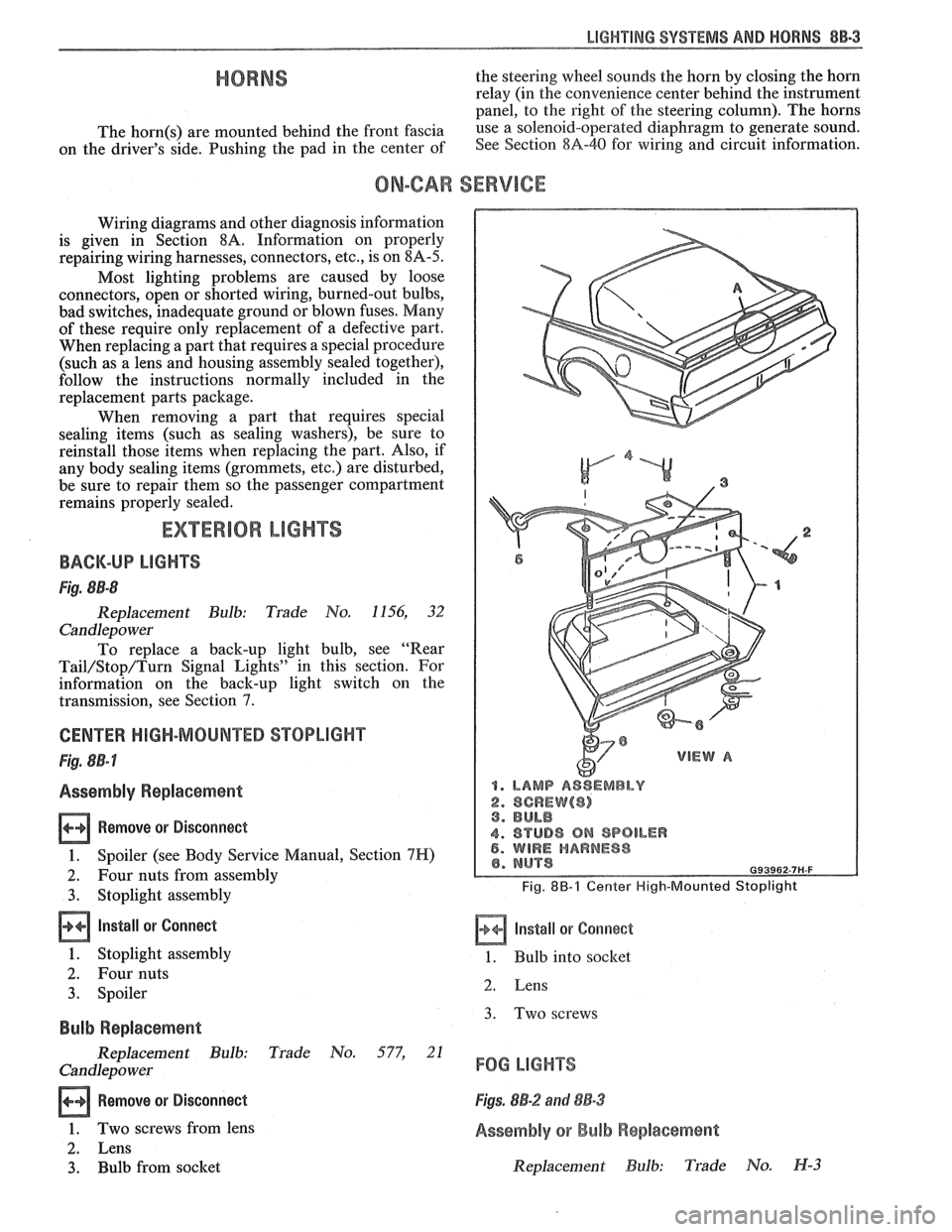
CENTER HIGH-MOUNTED STOPLIGHT
Fig. 8B-7
Assembly Replacement
Remove or Disconnect
1. Spoiler (see Body Service Manual, Section 7H)
2. Four nuts from assembly
3. Stoplight assembly
Install or Connect
1. Stoplight assembly
2. Four nuts
3. Spoiler
Bulb Replacement
Replacement Bulb: Trade No. 577, 21
Candlepo wer
Remove or Disconnect
1. Two screws from lens
2. Lens
3. Bulb from socket
1. LAMP ASSEMBLY
2. SCREW($) 3. BULB
4. STUD8 ON SPOILER 5. WIRE HARNESS
Fig. 8B-1 Center High-Mounted Stoplight
Install or Corrnect
1. Bulb into socket
2. Lens
3. Two screws
FOG LIGHTS
Figs. 8B-2 and 88-3
Assembly or Bulb Replacement
Replacement Bulb: Trade No. H-3
Page 1614 of 1825
INSTRUMENT PANEL. GAGES & CONSOLE 8C-3
tank only when ignition switch is turned to "ON" or
"ACCESSORY" positions.
When ignition is turned to "OFF" or "START"
positions, the pointer may come to rest at any position.
The letters
"E" and "F" on the fuel gage are used to
point out direction of indicator travel only.
TEMPERATURE WARNING LIGHT
The engine temperature warning light is
controlled by a thermal switch which senses engine
coolant temperatures.
When the ignition switch is turned to "START"
position, a test circuit is closed and the light will come
on to indicate whether the light is functioning properly.
It is important to note that with low boiling-point
coolants (such as plain water) the temperature light
may not come on even though the coolant is boiling.
GENERATOR WARNING LIGHT
The generator warning light, located in the
instrument cluster, should come on when the ignition
switch is turned
"ON" and engine is not running. If
not, either the bulb is burned out or wiring to generator
has an open circuit.
When the generator voltage output becomes
greater than the battery voltage, the
"GEN" light
should go out. This does not, however, indicate
whether the battery is being charged or if the voltage
regulator is functioning properly.
Checks of the charging system are covered in
Section 6D, 'Engine Electrical'.
ENGINE OIL PRESSURE LIGHT
The engine oil pressure warning light is mounted
in the instrument cluster and controlled by a pressure
operated switch located on the engine block. When the ignition switch is
in the
"run" or "start9' position, the
oil pressure light should come on. If not, the bulb is
burned out, there is an open circuit between the bulb
and the oil pressure switch, or there is an open circuit
between the oil pressure switch and the choke heater.
After the engine is running, the oil pressure light
should go out when the oil pressure reaches the correct
specification. If not an oil pressure problem, a faulty oil
pressure switch or an open circuit from the choke
heater fuse to the oil pressure switch is indicated.
"SERVICE ENGINE SOON" LIGHT
All cars have a "SERVICE ENGINE SOON"
light mounted in the instrument cluster. The
"SERVICE ENGINE SOON9' light should come on
during engine starting. The light may stay on
a short
time after the engine starts.
If the light comes on while
driving, service to the emission control system may be
required. See Section
6E and Section 8A-80,
'Instrument Cluster', for complete diagnosis and
wiring diagrams of the
""P;RVICE ENGINE SOON"
light circuit.
UPSHIFT INDICATOR LIGHT
If your vehicle has a manual transmission, there
may be an
''Upshift" light on the instrument panel.
This light is illuminated to indicate optimum shift
points throughout the range from optimum fuel
economy to optimum performance. When this light is
on, shift your transmission to the next higher gear
range if conditions permit. For fuel economy,
accelerate slowly and shift when the light goes on. For
performance, accelerate as desired and shift when the
light goes on.
Safe operation of the vehicle may require shifting
differently than indicated by the "Upshift" light to
adapt to weather, road or traffic conditions.
Downshifting one or more gears may be required
to keep the engine running smoothly or to maintain
satisfactory performance.
DIAGNOSIS
Diagnostic information for all instrument panel
electrical systems is found in Section
8A-80,
'Instrument Panel'.
CAUTION: When removing or
installing any electrical units,
disconnect the negative battery cable
to prevent possible short circuits
which could lead to personal injury
and/or property damage. When
replacing a speedometer or
odometer assembly, the law requires the
odometer reading of the replacement unit to
be set to register the same mileage as the
prior odometer.
if the same mileage cannot be
set, the
law requires that the replacement
odometer be set to zero and a label be
installed on the driver's door frame to show
the previous odometer reading and the date
of replacement.
GENERAL BNFORMATlOM
INSTRUMENT PANEL AND GAGES
The instrument panel is a single unit design and
and screws. To service the instrument panel and
all parts attach to the main instrument panel with clips components see Figs. 601 through 610.
Page 1638 of 1825
WINDSHIELD WIPER SYSTEMS - F CARLINE BE -11
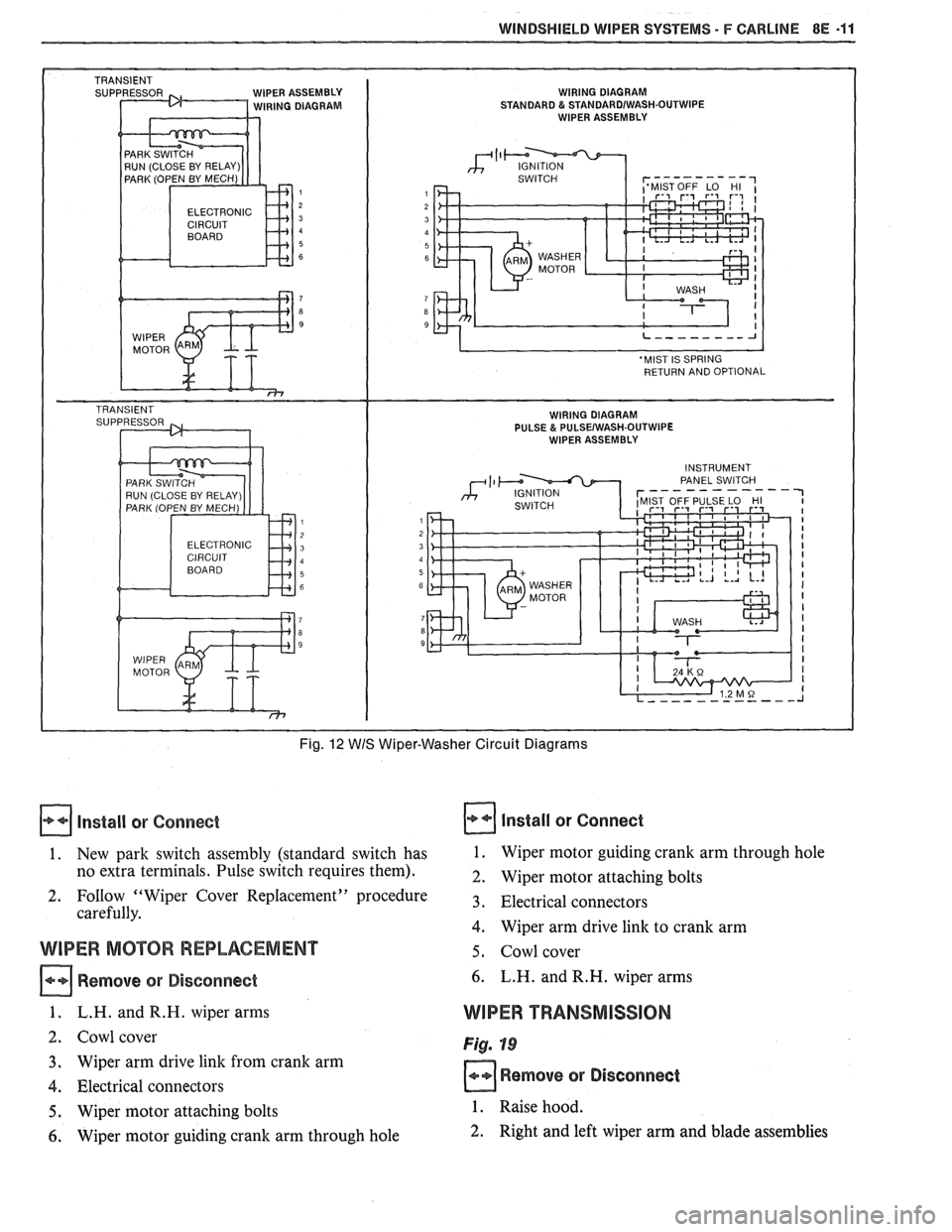
IPER ASSEMBLY WIRING DIAGRAM IRING DIAGRAM STANDARD & STANDARDIWASH.OUTWIPE WIPER ASSEMBLY
ELECTRONIC
Fig. 12 WIS Wiper-Washer Circuit Diagrams
Install or Connect
1. New park switch assembly (standard switch has
no extra terminals. Pulse switch requires them).
2. FoIlow "Wiper Cover Replacement" procedure
carefully.
WIPER MOTOR REPLACEMENT
Remove or Disconnect
1. L.H. andR.H. wiper arms
2. Cowl cover
3. Wiper arm drive link from crank arm
4. Electrical connectors
5. Wiper motor attaching bolts
6. Wiper motor guiding crank arm through hole
Install or Connect
1. Wiper motor guiding crank arm through hole
2. Wiper motor attaching bolts
3. Electrical connectors
4. Wiper arm drive link to crank arm
5. Cowl cover
6. L.H. and R.H. wiper arms
WIPER TRANSMISSION
Fig. 19
Remove or Disconnect
1. Raise hood.
2. Right and left wiper arm and blade assemblies
Page 1665 of 1825
98-2 CRUISE CONTROL
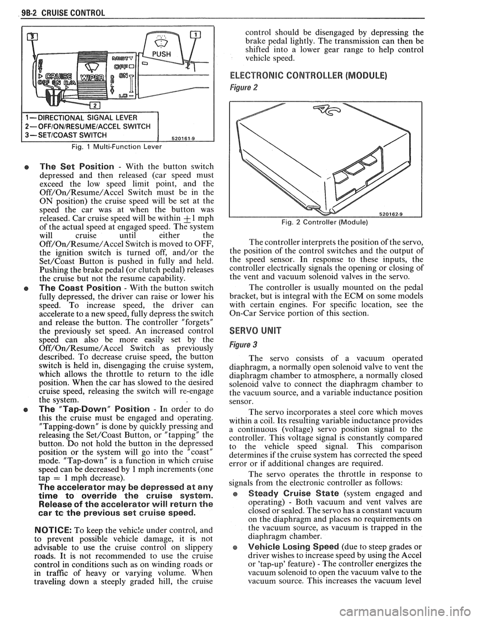
Fig. 1 Multi-Function Lever
e The Set Position - With the button switch
depressed and then released (car speed must
exceed the low speed limit point, and the
Off/On/Resume/Accel Switch must be in the
ON position) the cruise speed will be set at the
speed the car was at when the button was
released. Car cruise speed will be within
& 1 mph
of the actual speed at engaged speed. The system
will cruise until either the
Off/On/Resume/Accel Switch is moved to OFF,
the ignition switch is turned off, and/or the
Set/Coast Button is pushed in fully and held.
Pushing the brake pedal (or clutch pedal) releases
the cruise but not the resume capability.
The Coast Position - With the button switch
fully depressed, the driver can raise or lower his
speed. To increase speed, the driver can
accelerate to a new speed, fully depress the switch
and release the button. The controller "forgets"
the previously set speed. An increased control
speed can also be more easily set by the
Off/On/Resume/Accel Switch as previously
described. To decrease cruise speed, the button
switch is held in, disengaging the cruise system,
which allows the throttle to return to the idle
position. When the car has slowed to the aesired
cruise speed, releasing the switch will re-engage
the system.
e The "Tap-Down" Position - In order to do
this the cruise must be engaged and operating.
"Tapping-down" is done by quickly pressing and
releasing the
Set/Coast Button, or "tapping" the
button. Do not hold the button in the depressed
position or the system will go into the "coast"
mode. "Tap-down" is a function in which cruise
speed can be decreased by
1 mph increments (one
tap = 1 mph decrease).
The accelerator may be depressed at any
time
to override the cruise system.
Release of the accelerator will return the
car
te the previous set cruise speed.
NOTICE:
To keep the vehic:e under control, and
to prevent possible vehicle damage, it is not
advisable to use the cruise control on slippery
roads. It is not recommended to use the cruise
control in conditions such as on winding roads or
in traffic of heavy or varying volume. When
traveling down
a steeply graded hill, the cruise control
should be disengaged by depressing the
bralte pedal lightly. The transmission can then be
shifted into a lower gear range to help control
vehicle speed.
ELECTRONIC CONTROLLER (MODULE)
Figure 2
Fig. 2 Controller (Module)
The controller interprets the position of the servo,
the position of the control switches and the output of
the speed sensor. In response to these inputs, the
controller electrically signals the opening or closing of
the vent and vacuum solenoid valves in the servo.
The controller is usually mounted on the pedal
bracket, but is integral with the ECM on some models
with certain engines. For specific location, see the
On-Car Service portion of this section.
SERVO UNIT
Figure 3
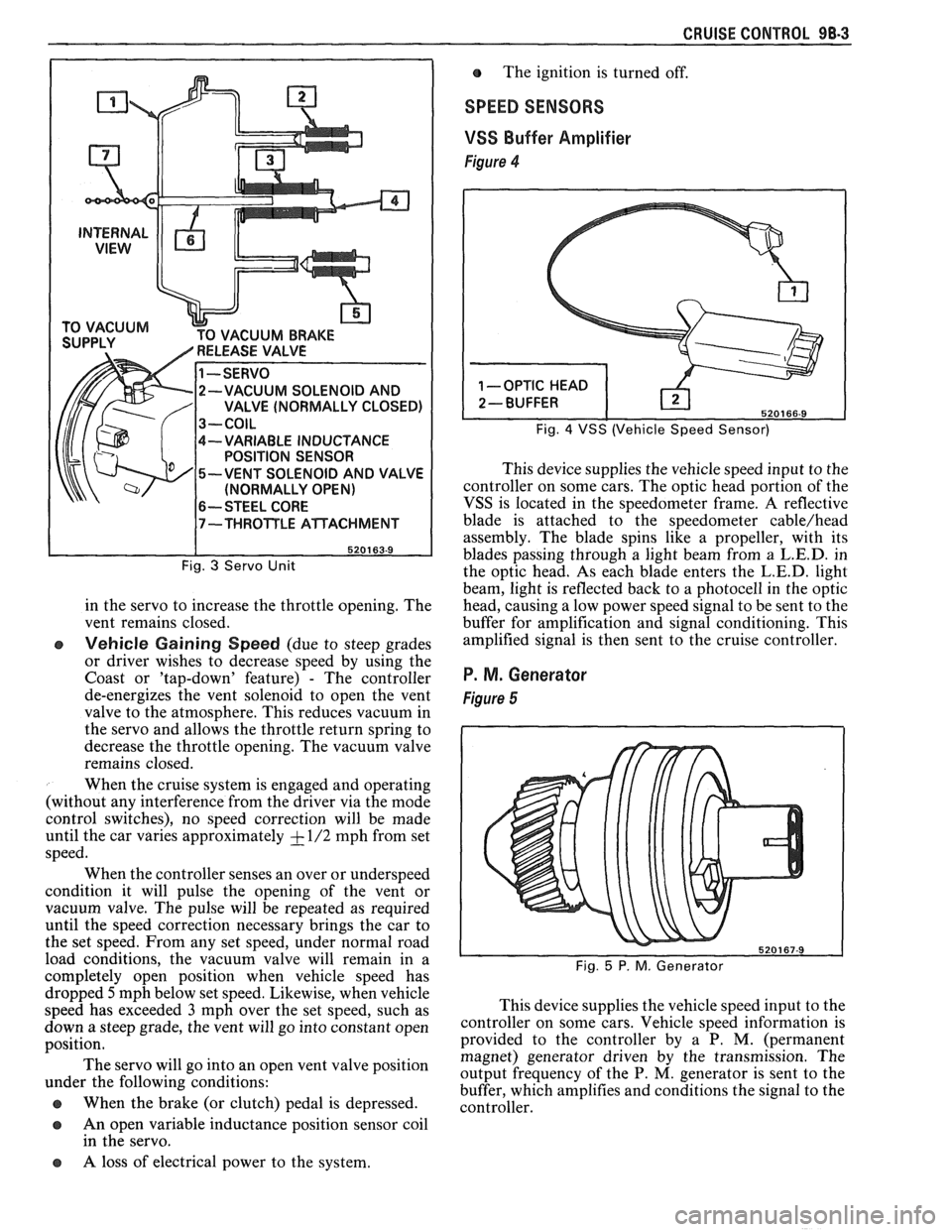
The servo consists of a vacuum operated
diaphragm, a normally open solenoid valve to vent the
diaphragm chamber to atmosphere, a normally closed
solenoid valve to connect the diaphragm chamber to
the vacuum source, and a variable inductance position
sensor.
The servo incorporates a steel core which moves
within a coil. Its resulting variable inductance provides
a continuous (voltage) servo position signal to the
controller. This voltage signal is constantly compared
to the vehicle speed signal. This comparison
determines if the cruise system has corrected the speed
error or if additional changes are required.
The servo operates the throttle in response to
signals from the electronic controller as follows:
Steady Cruise State (system engaged and
operating)
- Both vacuum and vent valves are
closed or sealed. The servo has a constant vacuum
on the diaphragm and places no requirements on
the vacuum source, as vacuum is trapped in the
diaphragm chamber.
e Vehicle Losing Speed (due to steep grades or
driver wishes to increase speed by using the Accel
or 'tap-up' feature)
- The controller energizes the
vacuum solenoid to open the vacuum valve to the
vacuum source. This increases the vacuum level
Page 1666 of 1825
CRUISE CONTROL 98-3
CUUM BRAKE
-VARIABLE INDUCTANCE
POSITION SENSOR
-VENT SOLENOID AND VALVE
(NORMALLY OPEN)
6-- STEEL CORE
Fig. 3 Servo Unit
in the servo to increase the throttle opening. The
vent remains closed.
e Vehicle Gaining Speed (due to steep grades
or driver wishes to decrease speed by using the
Coast or 'tap-down' feature)
- The controller
de-energizes the vent solenoid to open the vent
valve to the atmosphere. This reduces vacuum in
the servo and allows the throttle return spring to
decrease the throttle opening. The vacuum valve
remains closed.
When the cruise system is engaged and operating
(without any interference from the driver via the mode
control switches), no speed correction will be made
until the car varies approximately
+ - 1/2 mph from set
speed.
When the controller senses an over or underspeed
condition it will pulse the opening of the vent or
vacuum valve. The pulse will be repeated as required
until the speed correction necessary brings the car to
the set speed. From any set speed, under normal road
load conditions, the vacuum valve will remain in a
completely open position when vehicle speed has The
ignition is turned off.
SPEED SENSORS
VSS
Buffer Amplifier
Figure 4
Fig. 4 VSS (Vehicle Speed Sensor)
This device supplies the vehicle speed input to the
controller on some cars. The optic head portion of the
VSS is located in the speedometer frame. A reflective
blade is attached to the speedometer
cable/head
assembly. The blade spins like a propeller, with its
blades passing through a light beam from a
L.E.D. in
the optic head. As each blade enters the
L.E.D. light
beam, light is reflected back to a photocell in the optic
head, causing a low power speed signal to be sent to the
buffer for amplification and signal conditioning. This
amplified signal is then sent to the cruise controller.
P. M. Generator
Figure 5
dropped 5mph below set speed. Likewise, when vehicle
speed has exceeded
3 mph over the set speed, such as This
device supplies the vehicle speed input to the
down a steep grade, the vent will go into ,-onstant open ~0ntI-011er on some cars. Vehicle speed information is
position. provided
to the controller by a P. M. (permanent
magnet) generator driven by the transmission. The
The servo go into an 'Pen vent position output frequency of the P. M, generator is sent to the under the following conditions:
buffer, which amplifies and conditions the signal to the
@ When the brake (or clutch) pedal is depressed. controller.
a An open variable inductance position sensor coil
in the servo.
a A loss of electrical power to the system.
Page 1714 of 1825
DOORS - F STYLE 5H-1
SEC"610N 5H
DOORS
NOTICE: The anit-theft label found on some major sheet metal, engines, and transmissions must be masked
prior to painting, rustproofing, undercoating, etc. The mask
must be removed following the above operations.
Failure to keep the label clean and readable may result in liability for violation of Federal Vehicle Theft Prevention
Standard, and subject the vehicle owner to possible suspicion that the part was stolen.
Door Trim
...................................................... 5H- 1
Armrest and Pull Handle .......................... 5H- 1
Mirror Remote Controls/Bezel ................... 5H- 1
Inside Handles and Cover Plates ................ 5H- 1
Lock Knob .................................... .... ........... 5H-2
Trim Panel Assemblies .............................. 5H-2
Doors ............................................................ 5H-3
Door Weatherstrip ....................................... 5H-4
Side Roof Rail Weatherstrip ....................... 5H-4
Window Belt Sealing Strips ......................... 5H-6
Insulator Pads - Optional ............................ 5H-6
Inner Panel Water Deflectors ...................... 5H-6
Door Hinge System .................................. .... 5H-7
Door Side Hinge Strap ............................... 5H-8
Body Side Hinge Strap ................................ 5H- 10
Door Window ..................... .. ................... 5H- 10
Window Sash Channel ................................. 5H- 1 1
Window Regulator and Motor .................... 5H- 1 1
Filler Assembly (at Belt) ......................... ... . 5H- 13
Up Stop ............................ .. ...................... 5H- 14
Rear Guide Channel .................................... 5H- 15
DOOR SECnONS
This section of the manual contains the service
operations necessary for the removal, installation,
adjustment and sealing of door assemblies and
individual hardware and trim components. It is divided
into three subsections:
1. DOOR TRIM
- removal and installation
procedures for all door trim items.
2. DOORS - including hinges, door and side roof
rail weatherstrip and all lock system components.
3. EXTERIOR MOLDINGS - removal and
installation of exterior door moldings. Standard Mirror
......................................... 5H- 15
........................... Remote
Control Mirrors 5H- 15
Power-Operated Outside Mirror ................. 5H-16
Spring Clips .................................................. 5H- 16
Connecting Rods and Locking Rods .......... 5H-16
Inside Remote Handle ................................ 5H- 16
......................................... Outside Handle 5H- 16
............................. Lock Cylinder Assembly 5H- 17
...................................... Door Lock Striker 5H- 17
....................................... Door Wedge Plate 5H- 18
....................................... Door Jamb Switch 5H- 19
........................ Door Hardware Lubrication 5H- 19
Hardware Attachment Thread
.................................................. Locking 5H- 19
................................... Door Lock Assembly 5H- 19
............................ Power Door Lock System 5H-20
........................ Power Door Lock Actuator 5H-20
............. .................................... Bell Crank ... 5H-20
.......................................... Exterior Moldings 5H-20
.......................................... Spoiler on Door 5H-21
.......................................... Spoiler on Body 5H-2 1
DOOR OUTSIDE MIRROR REMOTE CONTROLS
AND BEZEL
On styles with remote control door outside
mirror, the remote control mirror cable must be
disengaged from the bezel on the door trim panel to
permit trim panel removal. To disengage the remote
cable from the door trim panel, refer to Figure
2.
DOOR INSIDE HANDLES AND COVER PLATES
Door inside handles are retained by either rivets
or spring clips (Fig.
4). On styles equipped with rivet
retained handles, the rivets are covered by a screw
retained cover plate that can be removed as shown in
Figure
3.
DOOR TRIM Removal and Installation
DOOR ARMREST AND PULL HANDLE 1.
ASSEMBLIES
The armrest and pull handle is a one-piece
assembly and is secured to the door inner panel with
screws after door trim panel is installed (Fig. 1). Clips hidden
by window regulator handles (Fig,
4) can be disengaged by depressing door trim
assembly enough to permit inserting tool J-9886
or equivalent between handle and trim panel or
plastic bearing plate (Fig.
5). Then, with tool in
same plane as inside handle, push tool as
indicated to disengage clip. Pull handle inboard
The removal of the door trim panel on styles with to
remove from
s$n>le. -
door armrest and pull handle assemblies requires 2. To install window regulator handles, engage
removal of screws inserted through the assembly's base retaining clip on handle. Position handle at same
into the armrest hanger plate and removal of the screw angle as opposite side handle and press handle
at the top of the pull handle section.
outboard until clip engages regulator spindle.