1988 PONTIAC FIERO transmission oil
[x] Cancel search: transmission oilPage 990 of 1825
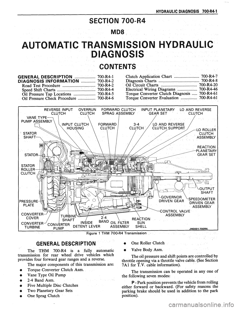
HYDRAULIC DIAGNOSIS 700.R4-1
SECTION 700-R4
AUTOMAT C TRANSM
CONTENTS
GENERAL DESCRIPTION
The THM 700-R4 is a fully automatic
transmission for rear wheel drive vehicles which
provides four forward gear ranges and a reverse.
The major components of this transmission are:
e Torque Converter Clutch Asm.
e Vane Type Oil Pump
e 2-4 Band Asm.
e Five Multiple Disc Clutches
0 Two Planetary Gear Sets
0 One Sprag Clutch
0 One Roller Clutch
e Valve Body Asm.
The oil pressure and shift points are controlled by
throttle opening via a throttle valve cable. (See Section
7A1 for T.V. cable information).
The transmission can be operated in any one of
the following seven modes:
P
- Park position prevents the vehicle from rolling
either forward or backward. (For safety reasons the
parking brake should be used in addition to the park
position).
Page 992 of 1825
HYDRAULIC DIAGNOSIS 700434-3
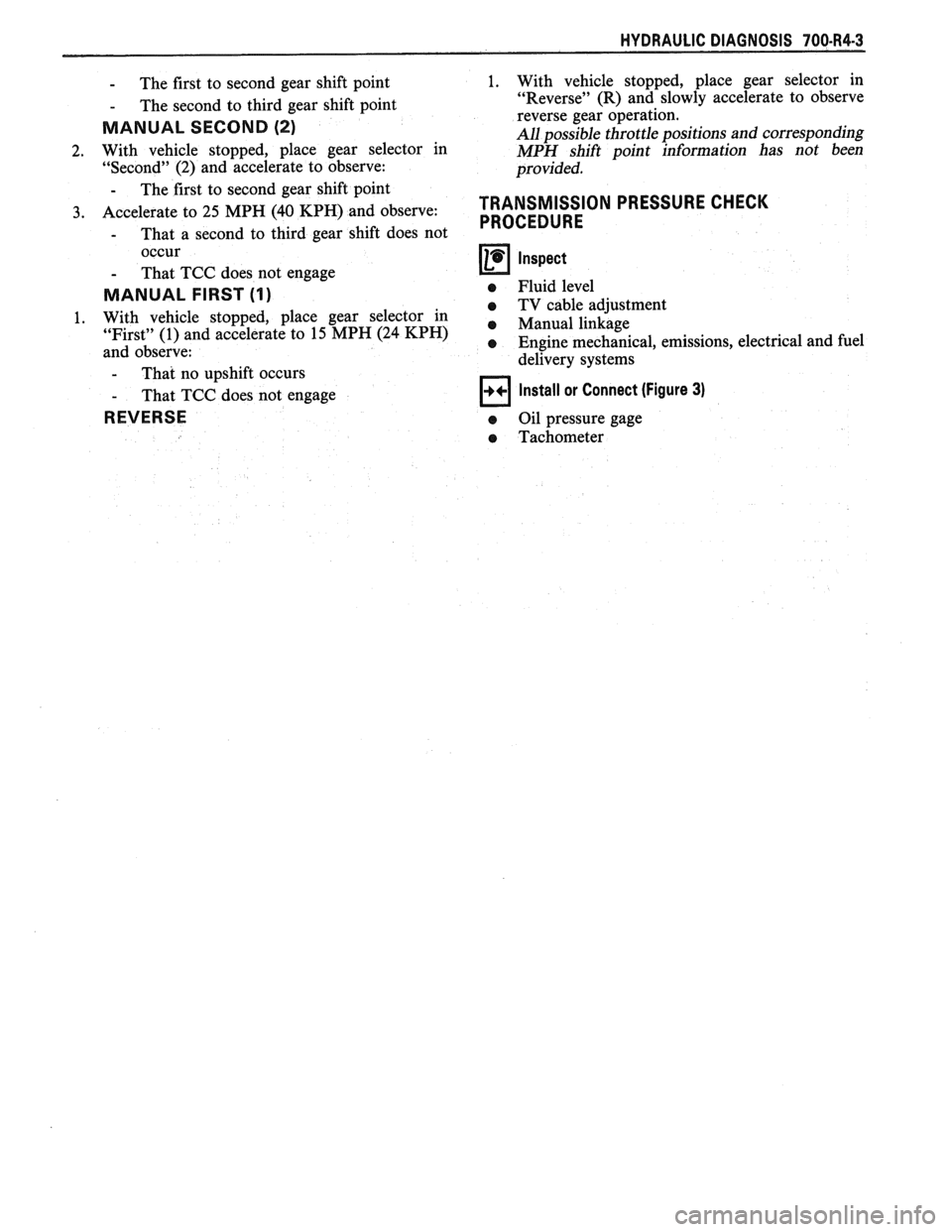
- The first to second gear shift point
- The second to third gear shift point
MANUAL SECOND (2)
2. With vehicle stopped, place gear selector in
"Second" (2) and accelerate to observe:
- The first to second gear shift point
3. Accelerate to 25 MPH (40 KPH) and observe:
- That a second to third gear shift does not
occur
- That TCC does not engage
MANUAL FIRST (I)
1. With vehicle stopped, place gear selector in
"First" (1) and accelerate to 15 MPH (24
KPH)
and observe:
- That no uoshift occurs
- That TCC does
REVERSE
1. With
vehicle stopped, place gear selector in
"Reverse" (R) and slowly accelerate to observe
reverse gear operation.
All possible throttle positions and corresponding
MPH shift point information has not been
provided.
TRANSMISSION PRESSURE CHECK
PROCEDURE
Inspect
e Fluid level
e TV cable adjustment
e Manual linkage
e Engine mechanical, emissions, electrical and fuel
delivery systems
not engage
Install or Connect (Figure 3)
a Oil pressure gage
a Tachometer
Page 995 of 1825
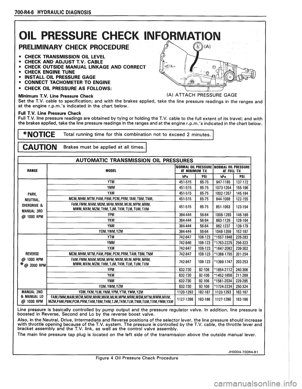
700-R4-6 HYDRAULIC DIAGNOSIS
L PRESSURE CHECK NFORMAT
PRELIMINARY CHECK PROCEDURE
0 CHECK TRANSMISSION OIL LEVEL 0 CHECK AND ADJUST T.V. CABLE
0 CHECK OUTSIDE MANUAL LINKAGE AND CORRECT
@ CHECK ENGINE TUNE
0 INSTALL OIL PRESSURE GAGE
CONNECT TACHOMETER TO ENGINE
0 CHECK OIL PRESSURE AS FOLLOWS:
Minimum T.V. Line Pressure Check (A) ATTACH PRESSURE GAGE
Set the T.V. cable to specification; and with the brakes applied, take the line pressure readings in the ranges and
at the engine
r.p.m.'s indicated in the chart below.
Full T.V. Line Pressure Check Full T.V. line pressure readings are obtained by tying or holding the T.V. cable to the full extent of its travel; and with
the brakes applied, take the line pressure readings in the ranges and at the engine
r.p.m.'s indicated in the chart below.
MODEL
Line pressure is basically controlled by pump output and the pressure regulator valve. In addition, line pressure is
boosted in Reverse, Second and Lo by the reverse boost valve.
Also, in the Neutral, Drive, Intermediate and Reverse positions of the selector lever, the line pressure should increase
with throttle opening because of the T.V. system. The pressure is controlled by the T.V. cable, the throttle lever and
bracket assembly and the T.V. link, as well as the control valve assembly.
The main line pressure tap plug is located on the left side of the transmission above the outside manual lever.
Figure
4 Oil Pressure Check Procedure
Page 997 of 1825
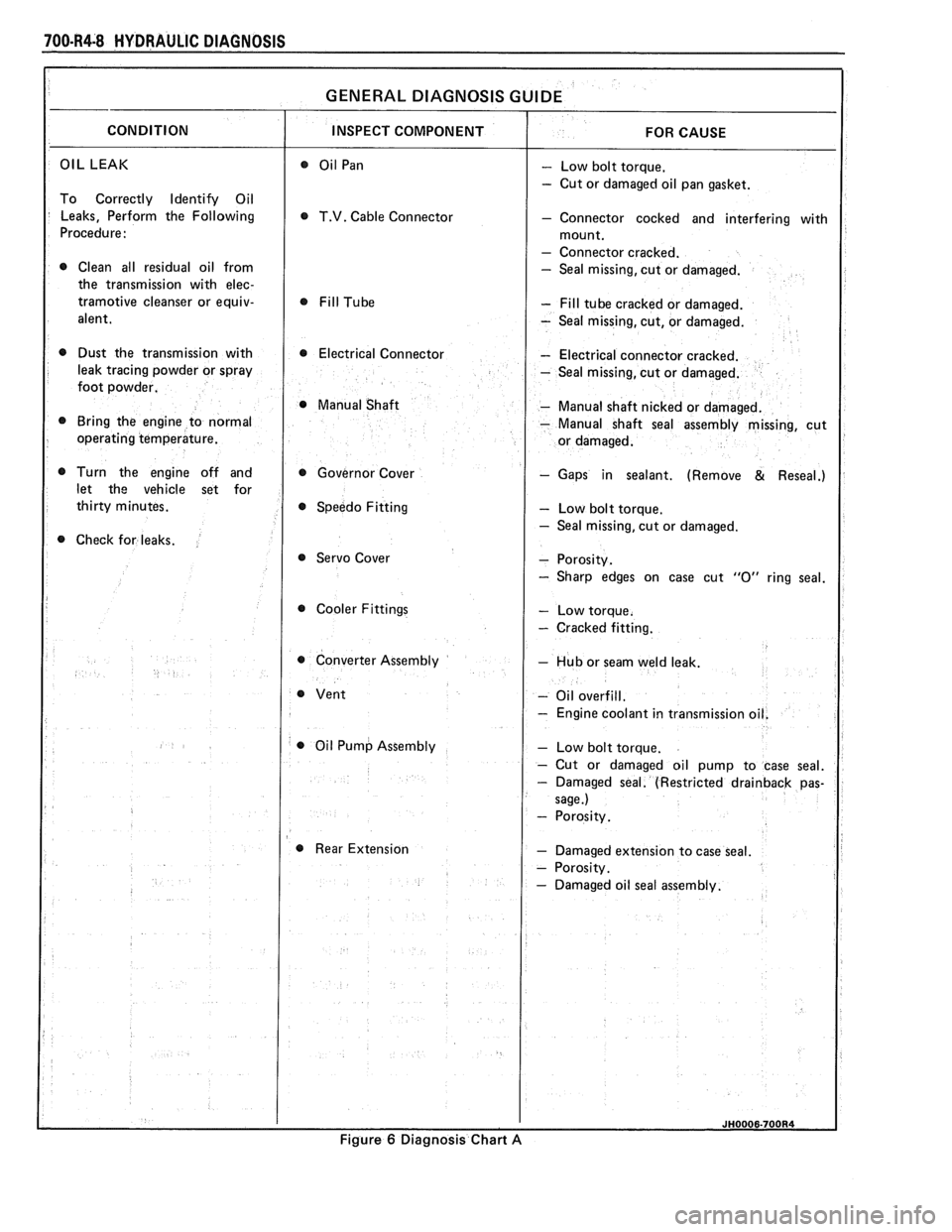
700-R4-8 HYDRAULIC DIAGNOSIS
OIL LEAK - Low bolt torque.
- Cut or damaged oil pan gasket.
To Correctly Identify Oil
Leaks, Perform the Following
T.V. Cable Connector - Connector cocked and interfering with
Procedure:
- Connector cracked.
0 Clean all residual oil from - Seal missing, cut or damaged.
the transmission with
elec-
tramotive cleanser or equiv- - Fill tube cracked or damaged.
alent.
- Seal missing, cut, or damaged.
0 Dust the transmission with 0 Electrical Connector - Electrical connector cracked.
leak tracing powder or spray
- Seal missing, cut or damaged.
foot powder.
@ Manual Shaft - Manual shaft nicked or damaged.
Bring the engine to normal
- Manual shaft seal assembly missing, cut
operating temperature.
Turn the engine off and Governor Cover
- Gaps in sealant. (Remove & Reseal.)
let the vehicle set for
Speedo Fitting
- Low bolt torque.
- Seal missing, cut or damaged.
Check for leaks.
@ Servo Cover
Cooler Fittings
- Cracked fitting.
0 Converter Assembly - Hub or seam weld leak.
- Oil overfill.
- Engine coolant in transmissio
0 Oil Pump Assembly
Rear Extension
- Damaged extension to case seal.
Figure
6 Diagnosis Chart A
Page 1010 of 1825
HYDRAULIC DIAGNOSIS 700.R4-21
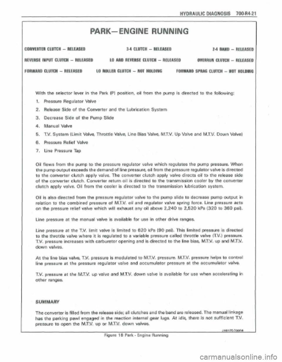
PARK- ENGlNE RUNNING
CONVERTER CLUTCH - RELEASED 34 CLUTCH - RELEASED 2.4 MUD - RELEASE0
REVERSE INPUT CLUTCH - RELEASED LO AND REVERIE CLUTCH - RELEASED OVERRUN CLUTCH - RELEASE0
FORWARD WUTCH - RELEASED LO ROUM CLUfCH - NOT HOLOlWO FORWARD SPRAQ CLUTCH - NaT HOLDIIYG
With the selector lever in the Park (PI position, oil from the pump is directed to the following:
1. Pressure Regulator Valve
2. Releasg Side of the Converter and the Lubrication System
3, Decrease Side of the Pump Slide
4. Manual Valve
5. T.V. System (Limit Valve, Throttle Valve, Line Bias Valve, M.T.V. Up Valve and M.T.V. Down Valve)
6. Pressure Relief Valve
7. Line Pressure Tap
Oil
flows from the pump to the pressure regulator vatve which regulates the pump pressure. When
the pump output exceeds the demand of line pressure, oil from the pressure regulator valve is directed
to the converter clutch apply valve. The converter clutch apply valve directs oil to the release side
of the converter clutch. Converter return oil is directed to the transmission cooler by the converter
clutch
apply valve, Oil from the cooler is directed to the transmission lubrication system.
Oil is also directed from the pressure regulator valve to the pump slide to decrease pump output in
relation to the combined pressure of M.T.V. oil and regulator valve spring force. Line pressure acts
on the pressure relief valve which will exhaust any oil above 2,240 to 2,520 kPa (320 to 360 psi).
Line pressure at the manual valve is available for use in other drive ranges.
Line pressure at the T.V. limit valv~ is limited to 620 kPa (90 psi). This limited pressure is directed
to the throttle valve where it is regulated to a variable pressure called throttle valve (T.V,) pressurn
T.V. pressure increases with carburetor opening and is directed to the line bias, MXV. up and M.T.V.
down valves.
At the line bias valve, T.V. pressure is modulated to M.T.V. pressure. M.T.V. pressure helps to control
line pressure
at the pressure regulator valve and accumulator pressure at the sceumulator valve.
T.V, pressure at the M.T.V. up valve and M.T,V. down valve js available for use when accelerating in
other ranges.
SUMMARY
The convener is filled from the release side; all clutches and the band are released. The manual linkage
has the parking pawl engaged in the reaction internal gehr lugs. At idle, them is not sufficient T,V.
pressure to open the MXV, up or M.T.V. down vakes.
JHO176.7OOR4 1
Figure 18 Park - Engine Running
Page 1014 of 1825
HYDRAULIC DIAGNOSIS 70064-2
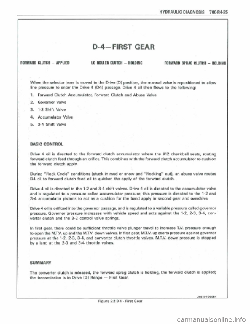
FORWARD CLUTCH - APPLIED
D-4-FIRST GEAR
LO ROLLER CLUTCH - HOLDlllO FORWARO SPRRQ CLUTCH - HOLDING
When the selector lever is moved to the Orive {Dl position, the manual valve is repositioned to allow
line pressure to enter the Drive 4 104) passaga Drive 4 oil then flows to the following:
1. Forward Clutch Accumulator, Forward Clutch and Abuse Valve
2. Governor Valve
. 3. 1-2 Shift Valve
4, Accumulator Valve
5. 3-4 Shift Valve
BASIC CONTROL
Drive 4 oil is directed to the forward clutch accumulator where the #I2 checkball seats, routing
forward clutch feed through an orifice. This combines with the forward clutch accumuIator to cushion
the forward clutch
apply,
During "Rock Cyclea' cpnditions (stuck in mud or snow and "Rocking" out), an abuse valve routes
D4 oil to forward clutch feed oil to quicken the apply of the forward clutch.
Driw 4 oil is directed to the 1-2 and 3-4 shift valves, Drive 4 oil is directed to the accumulator valve
and is regulated to a pressure called accumulator pressure; this pressure is directed to the 1-2 and
3-4 accumulator pistons to act as a cushion for the band apply in second gear and overdrive.
'Drive
4 oil is orificed into the gwernor passage, and is regulated to a variable pressure called governor
pressure. Governor pressure increases with vehicle speed and acts against the 1-2, 2-3, 3-4, con-
verter clutch and the 3-2 control valve springs.
In first gear, there could
be sufficient throttle valve plunger travel to increase T.V. pressure enough
to open the MW. up and the M.T.V. down valves. In first gear, MXV. up exerts pressure against governor
pressure at the 1-2, 2-3, 3-4, and converter clutch throttle valves. M.T.V. down pressure is stopped
by a land at the 2-3 and 34 throttle valves,
SUMMARY
The converter clutch is released, the forward sprag dutch is holding, the forward clutch is applied;
the transmission is i'n Drive (Dl Range - First Gear.
I Jn0177-700M Figure 22 D4 - First Gsar
Page 1016 of 1825
HYDRAULIC PlAONOSlS fOO-R4-27
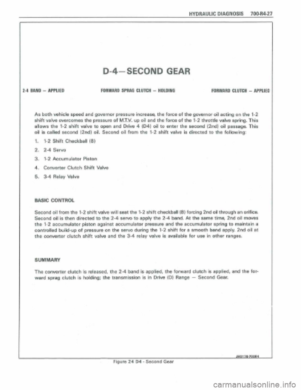
D-4-SECOND GEAR
FORWARD SPRAE CLUTCH - HOLDlMO 24 BAND - APPLIED FOIWARD CLUTCH - APPLIEP
As both vehicle speed and govanor pressure increase, the force of the governor oil acting on the 1-2
shift valve overcomes the pressure of M.T.V. up oil and the force of the 1-2 throttle valve spring. This
allows the 1-2 shift valve to open and Drive 4 (041 oil to enter the second (2nd) oil passage. This
oil is called second (2nd) oil. Second oil from the 1-2 shift valve is directed to the following:
1. 1-2 Shift Checkbatl (8)
2, 2-4 Servo
3. 1-2 Accumulator Piston
4. Converter Clutch Shift Valve
5. 3-4 Relay Valve
WlC CONTROL
Second ail from the 1-2 shift valve will seat the 1-2 shift checkball (8) forcing 2nd oil through an orifice.
Second oil Is then directed to the 2-4 servo to apply the 2-4 band. At the same time, 2nd oil moves
the 1-2 eccumulator piston against accumulator pressure and the accumulator spring to maintain a
controlled build-up of pressure on the servo during tho 1-2 shift for a smooth bend apply 2nd oil at
the converter clutch shift vatve and the 3-4 relay valve is availabl~ for use in other ranges.
SUMMARY
The converter clutch is released, the 2-4 band is applied, the forward clutch is applied, and the for-
ward spmg clutch is holding; the transmission is in Drive (Dl Range - Second Gear,
dH017B.7OOR4 -
Figure 24 D4 - Second Gear
Page 1020 of 1825
HYDRAULIC DfAQNOSIS 70044-31
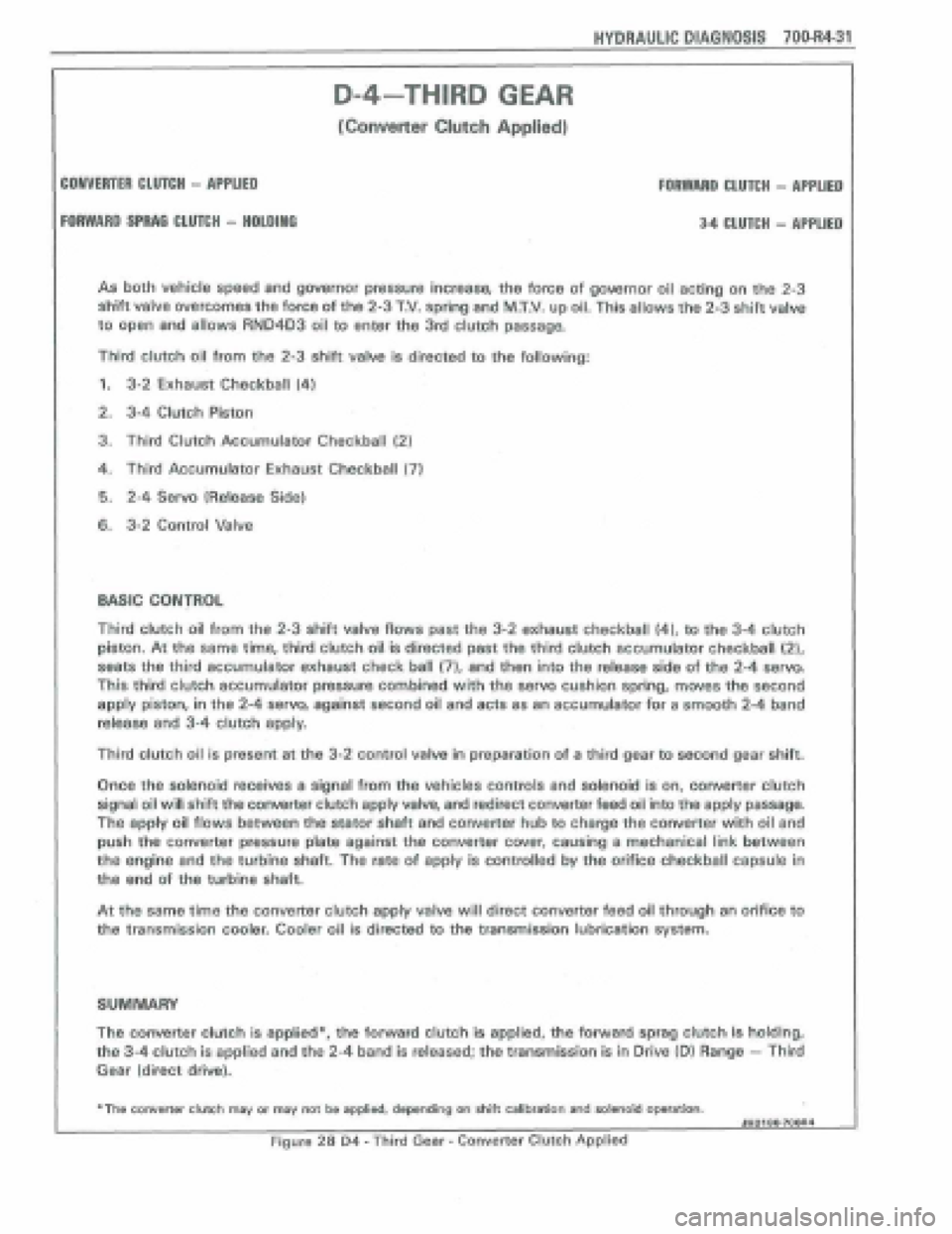
As both vehicle speed and governor pressure increase, the force of gowrnor oil acting on the 2-3
shift valve overcomes the force of the 2-3 T.V. spring and MXV. up oil, This allows the 2-3 shift valve
to
open and allows RN04D3 oil to enter the 3rd clutch passage.
Third clutch oil from the 2-3 shift valve is directed to the following:
1. 3-2 Exhaust Checkball (4)
2. 3-4 Clutch Piston
3. Third Clutch Accumulator Checkball (2)
4. Third Accumulator Exhaust: Checkball (7)
6. 2-4 Servo 1Release Side)
6. 3-2 Control Valve
D-4-THIRD GEAR
[Converter CItPtch Applied)
COMVERTER CtUTCli - APPLIED FOAWARD CLUTCH - APPLIED
FORWARD SFRAG CLU7CH - HPLDINO 34 CLUTCH - APPLIED
Third clutch oil from the 2-3 shift valve flows past the 3-2 exhaust checkball (4), to the 3-4 clutch
piston. At the same time, third clutch oil is directed past the third clutch accumulator checkball {2),
seats the third accumula'tor exhaust check ball (71, and then into the release side of the 2-4 serva
This third clutch accumulator pressure combined with the servo cushion spring, moves the second
apply piston, in the 2-4 servo, against second oil and acts as an accumulator for a smooth 2-4 band
release and 3-4 clutch apply.
Third clutch oil is present at the 3-2 control valve In preparation of a third gear to second gear shift.
Once the solenoid teceives a signal from the vehicles controls and solenoid is on, convefier clutch
signal oil will shift the converter clutch apply valve, and redirect converter feed oil into the apply passage.
the apply oil flows between the stator shaft and converter hub to charge the converter with oil and
push the converter pressure plate against the converter cwer, causing a mechanical link between
the engine and the turbhe shaft. The rate of apply is controlled by the orifice checkball capsule in
tha end of the turbine shaft.
At tho same time the converter clutch appfy valve will direct converter feed oil through an orifice to
the transmission cooler. Cooler oil is directed to the transmission lubrication sysm.
SUMMARY
The converter clutch is applied*, the forward clutch is applied, tho forward sprag clutch is holding,
the 3-4 clutch is applied and the 2-4 band is released; the transmission is in Drive (Dl Range - Third
Gear (direct drive).
+The converter clwh msy or may not be applied, depending on Aitt calibration and salenoid operation. JHOI 80+7OOA4
Figure 28 D4 - Third Gear - Converter Clutch Applkd