1988 PONTIAC FIERO sensor
[x] Cancel search: sensorPage 1612 of 1825
INSTRUMENT PANEL, GAGES & CONSOLE 8C-'I
SECTION 8C
NSTRUMENT PANEL, GAGES & CONSOLE
CONTENTS
General Description ................................... 8C-1
Instrument Panel and Gages ........................ 8C-1
Printed Circuit .......................................... 8C-1
Instruments ................................................... 8C- 1
Speed Sensors
............................ .. ............. 8C- 1
Pinion Gear
............................................. 8C-2
Photo Speed Sensor ................................ 8C-2
PM Generator ................... .. ...... ............... 8C-2
Speedometer ................................................ 8C-2
Mechanical ....................... .. .................... 8C-2
Quartz ........................ .. .......................... 8C-2
Digital .................... .. ...... ................. 8C-2
Fuel Gage .................................................... 8C-2
Temperature Warning Light ...................... 8C-3
Generator Warning Light ............................ 8C-3
Engine Oil Pressure Light ............................ 8C-3
"Service Engine Soon" Light ....................... 8C-3
Upshift Indicator Light .............................. 8C-3
Diagnosis .................... .. ........................... 8C-3
General Information .................................. 8C-3
Instrument Panel & Gages ...................... ..... 8C-3
On-Car Service ......................... .. ........... 8C-4
Instrument Panel Pad ................................... 8C-4
Instrument Panel Cluster ........................... 8C-4
Instrument Panel Carrier ............................. 8C-4
Headlight Switch .......................................... 8C-4
Console Mounted Switches and
Accessories
............................................... 8C-4
Console ......................................................... 8C-4
Speedometer .................................................. 8C-5
Illustra3ions ................................................. 8C-5
IP Pad ........................................................... 8C-5
IP Carrier ................................................... 8C-6
Instrument Cluster ....................................... 8C-6
Lower IP Covers ......................................... 8C-7
IP Trimplates ............................................... 8C-7
IP Hush Panels; with A/C .......................... 8C-8
..................... IP Lower Trim Pad (Console) 8C-8
Map Holder or Map Pocket ........................ 8C-8
IP Hush Panels; without A/C ..................... 8C-9
Radio Mounting ........................................... 8C-9
Subwoofer & Hatch Release
Switches/Covers ........................................ 8C- 10
Foglamp Switch/Cover ................................ 8C- 10
Oil Pressure and Temperature
Switches
..................................................... 8C-11
Heater/Ventilation/Defroster
Ductwork .................................................. 8C- 12
A/C and Defroster Ductwork ..................... 8C-13
Ram Vent System Ductwork ....................... 8C-14
Console Mounted Switches
&
Accessories ................................................. 8C- 14
Dash Insulators
............................................ 8C- 15
Heater Floor Outlet
..................................... 8C-15
................ Headlamp/Parking Lamp Switch 8C- 15
............. Dash Mounted Accessory Switches 8C- 15
GENERAL DESCRIPTION
INSTRUMENT PANEL AND GAGES
INSTRUMENTS
Instruments consist of fuel gage, temperature
The instrument panel on most cars is a sing,e unit indicator light, generator light, oil pressure indicator
design and all parts attach to the main instrument light, and speedometer. See Section 9F for optional
panel with clips and screws. To service the instrument Gages and tachometer. Service on instruments
panel and components see on-car service information, can be obtained through authorized repair stations.
However, knowledge of instrument circuit checks will
PRINTED CIRCUIT
All models are equipped with printed circuits
which supply current to most instrument panel lights
and instruments. These circuits are made of copper foil
which is die cut and bonded to a polyester base film
(usually mylar). The printed circuit electrical power is
supplied by a connector containing several wires, as
shown in the instrument panel wiring harness
installation instructions. The connector also helps
retain the printed circuit to the speedo cluster. The rest
of the circuit is retained by additional connectors (if
used) and snap-in
bulbs/sockets. For individual
printed circuit diagrams, see Section
8A-80/8 1/82/83,
'Instrument Panel'. help
in determining if operating difficulties lie in the
instrument itself or its related circuit.
Instruments have been designed for easy removal
by elimination of separate wiring. With the wiring
provisions integrated with the instrument panel wiring,
the instruments can be removed after removing the
trim and lens.
SPEED SENSORS
There are three speed sensors currently in use:
1. PINION GEAR; used in mechanical systems
2. PHOTO SPEED SENSORS; used in mechanical
systems
3. PM GENERATOR; used in electronic systems
Page 1613 of 1825

842-2 INSTRUMENT PANEL. GAGES & CONSOLE
Pinion Gear
The PINION GEAR is attached to the
traaasmission/transaxle output shaft and rotates in
proportion to the speed of the car. This rotation is
transferred from the pinion gear to the speedometer
head by the speedometer cable.
Photo Speed Sensor
On vehicles that use a mechanical drag-cup
speedometer, the PHOTO SPEED SENSOR is
inserted into the frame of the mechanical speedometer
to provide an electrical feedback to the ECM that
represents vehicle speed. The ECM needs to know how
fast the car is traveling in order to control and operate
the cruise control, cooling fan, and transmission and
evaporative systems.
The photo speed sensor is made up of two special
electronic devices: a Eight-Emitting Diode (LED) and
a photo transistor (a light-sensitive amplifying device).
In the mechanical speedometer, there is a reflective
blade attached to the rotating magnet that is polished
to
reflect light from the LED back to the photo
transistor. Whenever the light strikes the photo
transistor, it conducts electricity. The rate that the
transistor conducts and does not conduct is
proportional to the speed of the magnet, which reflects
the speed of the vehicle. This voltage signal from the
photo transistor is sent to a buffer amplifier (part of the
speed sensor) to be conditioned to a signal the ECM
can understand and use.
PM Generator
The PM (Permanent Magnet) GENERATOR is
a small
AC generator used to sense vehicle speed. The
shaft of the generator fits into a pinion gear in the
transmission/transaxle output shaft (as does the cable
in
a mechanical system).
When the output shaft rotates, the magnet rotates
and generates a voltage. Except for the permanent
magnet, the
PM Generator is exactly like a miniature
alternator. The PM generator is constructed to provide
a voltage whose frequency is about
1.1 cycles per
second for every mile per hour of vehicle speed. This
signal is sent to a buffer amplifier, and then to the
speedometer and the
EGM.
SPEEDOMETER
The speedometer is a road speed indicator with
an odometer to record total mileage, and, on some cars,
a resettable trip odometer.
The major types of speedometers in use are
mechanical instruments and electronic instruments.
Mechanical speedometers use a dial needle to indicate
road speed. Electronic speedometers include
instruments that use a dial indicator and those using
bar-graph
LCD's (Liquid Crystal Displays) or VTF
(Vacuum Tube Fluorescent) displays.
Meehanice! Speedometers
A mechanical speedometer uses a cable driven
(through a pinion gear) by the transmission output
shaft. The cable connects to a magnetic drag-cup inside the
speedometer, which rotates the speedometer
needle. The end of the rotating cable causes a small bar
magnet to rotate within a metal cup. As the magnet
rotates within the cup, it magnetically attracts (drags)
the metal cup along behind it. Two things work to
prevent the cup from rotating as quickly as the magnet.
1. The distance of the magnet from the cup reduces
its effect on the cup.
2. A counterspring is wound around the shaft of the
cup in such a way as to oppose the normal
rotation of the cup. The counterspring loads the
drag-cup to give correct indication of the speed,
prevent needle overshoot, and also to return the
drag cup to a zero point.
Mechanical speedometers require a photo speed
sensor to provide road speed information for the ECM
and other systems, such as Cruise Control and the TCC
(Torque Converter Clutch).
The odometer on these instruments consists of
numbered wheels that are rotated by the speedometer
cable through worm gears.
Quartz Speedometer
The quartz speedometer is an electrically driven
instrument. The indicator needle is driven by a
precision DC motor, and is countersprung to provide
a mechanical load, prevent overshoot of the needle, and
return the indicator to zero when the road speed is
zero.
The source of speed information for a quartz
speedometer is the PM generator. From the PM
generator, speed information goes to the buffer
amplifier to be converted to digital voltage, and then
to the cluster circuitry, which interprets the speed of
the vehicle and produces small voltage to apply to the
speedometer motor.
The odometer on this instrument consists of
numbered wheels that are electrically driven by a
special precision DC motor called a stepper motor.
Digital Speedometer
Digital clusters utilize two types of displays: LCD
(Liquid Crystal Display) and VTF (Vacuum Tube
Fluorescent). They are used in digital speedometers
and bar-graph tachometers, fuel gages, etc.
Speed information entering the cluster from the
buffer amplifier is interpreted by a microcomputer
which controls the speed indication, the tachometer
display and the odometer reading.
The odometers associated with these instruments
utilize either numbered wheels driven by a small motor
or electronic displays. With an electronic display, the
mileage reading is stored in a computer chip (called a
non-volatile RAM chip; NVRAM) that does not
become 'erased' when the vehicle is turned off,
as the
display does not retain the information.
FUEL GAGE
An electrical fuel gage is used on all models,
consisting of an instrument panel gage and a fuel tank
pick-up. The fuel gage indicates the quantity of fuel in
Page 1622 of 1825
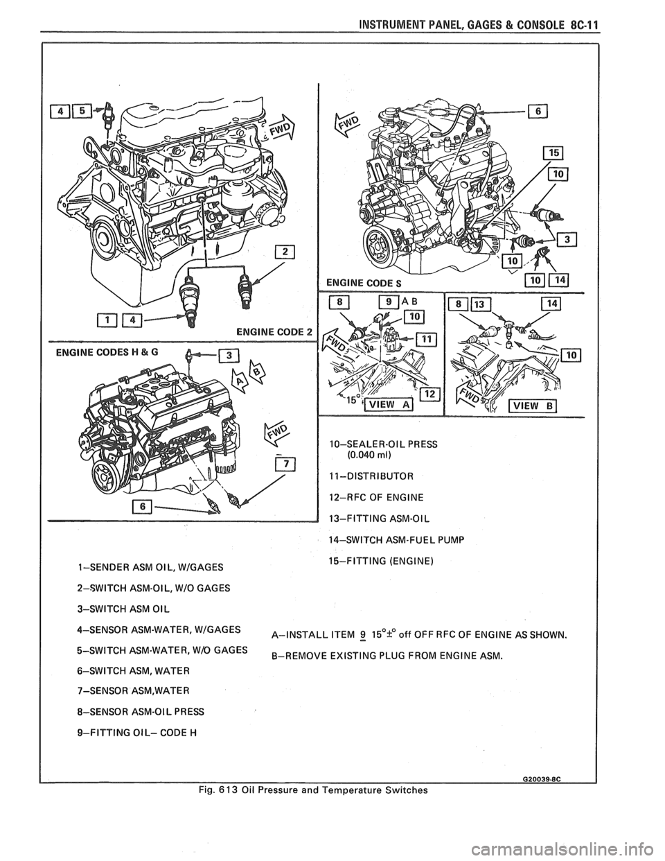
INSTRUMENT PANEL. GAGES & CONSOLE 8C-11
ENGINE CODE 2
ENGINE CODES H & G
10-SEALER-OI L PRESS
(0.040 ml)
12-RFC OF ENGINE
13-FITTING ASM-OIL
14-SWITCH ASM-FUEL PUMP
I
1-SENDER ASM OIL, WIGAGES 15-FITTING (ENGINE)
I
2-SWITCH ASM-OI L, WIO GAGES
3-SWITCH ASM OIL
4-SENS0R ASM-WATER' A-INSTALL ITEM g 15'9 off OFF RFC OF ENGINE AS SHOWN.
ASM-WATER' W1O GAGES B-REMOVE EXISTING PLUG FROM ENGINE ASM.
6-SWITCH ASM, WATER
8-SENSOR ASM-OI L
PR ESS
I 9-FITTING OIL- CODE H
Fig.
6 13 Oil Pressure and Temperature Switches
Page 1664 of 1825
CRUISE CONTROL 9B-1
SECTION 9B
SE CONTROL
CONTENTS
General Description ................................... 9B-1
Off/On/Resume/Accel Switch
Operation
................................................ 9B- 1
Set/Coast Button Switch .............................. 9B- 1
Electronic Controller (Module) .................... 9B-2
Servo Unit ..................................................... 9B-2
Speed Sensors ............................................. 9B-3
VSS Buffer Amplifier ................................ 9B-3
PM Generator Speed Signal ..................... 9B-3
Vacuum Supply ............................................. 9B -4
Electrical and Vacuum Release
Switches
..................................................... 9B-4
Electrical Harness ...................................... 9B-4
Diagnosis .................................................. 9B-4
Cruise System Surges .................................... 9B-4
Cruise Set Speed High or Low ..................... 9B-4
Excessive Cruise Speed Loss on Hills .......... 9B-4
Cruise Tap-Up and Tap-Down .................... 9B-4
On-Gar Service (Illustrated) ..................... 9B-6
Cruise Release Switches ............................... 9B-6
............................. Cruise Processor Module 9B-6
Vacuum Harness and Cable Routing -
VIN E ..................................................... 9B-7
Vacuum Harness and Cable Routing -
VIN S ......................................................... 9B-8
Vacuum Harness and Cable Routing -
VIN F,8 ..................................................... 9B-9
Servo Mounting - VIN S,F .......................... 9B-10
....................... Servo and Bracket - VIN E 9B-10
Vacuum Tank - VIN S,F,E ....................... 9B-10
GENERAL DESCRIPTION
Cruise control is a speed control system which
maintains a desired car speed under normal driving
conditions. However, steep grades up or down may
cause variations in the selected speeds. The electronic
cruise control system has the capability to cruise, coast,
resume speed, accelerate, and "tap-up" and
" tap-down" .
The main parts of the cruise control system are
the mode control switches, controller (module), servo
unit, speed sensor, vacuum supply, electrical and
vacuum release switches, and electrical harness.
The cruise control system uses vacuum to operate
a throttle servo unit. The servo unit maintains a desired
car speed by trapping vacuum in the servo unit at the
proper servo position. The controller monitors vehicle
speed and servo position and operates the vacuum and
vent valves in the servo to maintain desired speed. The
controller contains a low speed limit which will prevent
system engagement below a minimum speed of about
25 mph. The operation of the controller is controlled
by mode control switches located in the end of the
directional signal lever. To disengage the system, two
release switches are provided. An electrical release
switch mounted on the brake pedal bracket (brake and
clutch pedal bracket on cars equipped with manual
transmission) disengages the system electrically when
the brake pedal (or clutch pedal) is depressed. A
vacuum release valve, mounted on the brake pedal
bracket, vents the trapped vacuum in the servo to
atmosphere when the brake pedal is depressed,
allowing the servo unit to quickly return the throttle
to idle position.
.
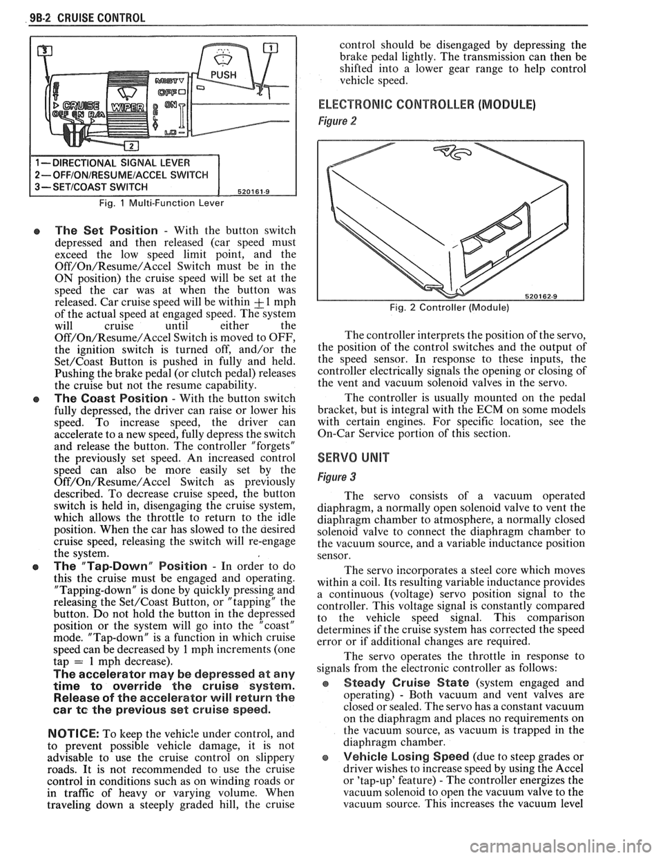
OFF/ON/RESUME/ACCEL SWITCH
(OPERATION)
Figure 1
The Off/On/Resume/Accel Switch has three
positions. This switch turns the cruise control system
ON and OFF and also returns cruise control operation
to the last speed setting when MOMENTARILY
moved towards the R/A position after braking. (Do
not hold the slider in the R/A position
... release it
immediately.) If the slider is held in the R/A position
for more than one second, the system goes into the
Accel mode. To accelerate the car, move the slider
switch to the R/A position and hold it there until the
car reaches the desired speed. When the slider switch
is released, the system will maintain the new cruise
speed. In order to use the Accel mode, the cruise
OFF/ON/Resume/Accel switch must be in the "ON"
position and the car must be above the low speed limit
of
25 mph.
The slide switch can also be used to "tap-up" car
speed. In order to do this the cruise must be engaged
and operating. "Tapping-up" is done by quickly
pressing the slide switch toward the R/A position and
quickly releasing it, or "tapping" the lever. Do not hold
the lever in the R/A position or the system will go into
the Accel mode. "Tap-up" is a function in which cruise
speed can be increased by
1 mph increments (one tap
= 1 mph increase).
SET/COAST BUTTON SWITCH
Figure 1
The cruise control Set/Coast Switch (located in
the end of the turn signal lever) has two positions
-
"Normal" and "Depressed".
Page 1665 of 1825
98-2 CRUISE CONTROL
Fig. 1 Multi-Function Lever
e The Set Position - With the button switch
depressed and then released (car speed must
exceed the low speed limit point, and the
Off/On/Resume/Accel Switch must be in the
ON position) the cruise speed will be set at the
speed the car was at when the button was
released. Car cruise speed will be within
& 1 mph
of the actual speed at engaged speed. The system
will cruise until either the
Off/On/Resume/Accel Switch is moved to OFF,
the ignition switch is turned off, and/or the
Set/Coast Button is pushed in fully and held.
Pushing the brake pedal (or clutch pedal) releases
the cruise but not the resume capability.
The Coast Position - With the button switch
fully depressed, the driver can raise or lower his
speed. To increase speed, the driver can
accelerate to a new speed, fully depress the switch
and release the button. The controller "forgets"
the previously set speed. An increased control
speed can also be more easily set by the
Off/On/Resume/Accel Switch as previously
described. To decrease cruise speed, the button
switch is held in, disengaging the cruise system,
which allows the throttle to return to the idle
position. When the car has slowed to the aesired
cruise speed, releasing the switch will re-engage
the system.
e The "Tap-Down" Position - In order to do
this the cruise must be engaged and operating.
"Tapping-down" is done by quickly pressing and
releasing the
Set/Coast Button, or "tapping" the
button. Do not hold the button in the depressed
position or the system will go into the "coast"
mode. "Tap-down" is a function in which cruise
speed can be decreased by
1 mph increments (one
tap = 1 mph decrease).
The accelerator may be depressed at any
time
to override the cruise system.
Release of the accelerator will return the
car
te the previous set cruise speed.
NOTICE:
To keep the vehic:e under control, and
to prevent possible vehicle damage, it is not
advisable to use the cruise control on slippery
roads. It is not recommended to use the cruise
control in conditions such as on winding roads or
in traffic of heavy or varying volume. When
traveling down
a steeply graded hill, the cruise control
should be disengaged by depressing the
bralte pedal lightly. The transmission can then be
shifted into a lower gear range to help control
vehicle speed.
ELECTRONIC CONTROLLER (MODULE)
Figure 2
Fig. 2 Controller (Module)
The controller interprets the position of the servo,
the position of the control switches and the output of
the speed sensor. In response to these inputs, the
controller electrically signals the opening or closing of
the vent and vacuum solenoid valves in the servo.
The controller is usually mounted on the pedal
bracket, but is integral with the ECM on some models
with certain engines. For specific location, see the
On-Car Service portion of this section.
SERVO UNIT
Figure 3
The servo consists of a vacuum operated
diaphragm, a normally open solenoid valve to vent the
diaphragm chamber to atmosphere, a normally closed
solenoid valve to connect the diaphragm chamber to
the vacuum source, and a variable inductance position
sensor.
The servo incorporates a steel core which moves
within a coil. Its resulting variable inductance provides
a continuous (voltage) servo position signal to the
controller. This voltage signal is constantly compared
to the vehicle speed signal. This comparison
determines if the cruise system has corrected the speed
error or if additional changes are required.
The servo operates the throttle in response to
signals from the electronic controller as follows:
Steady Cruise State (system engaged and
operating)
- Both vacuum and vent valves are
closed or sealed. The servo has a constant vacuum
on the diaphragm and places no requirements on
the vacuum source, as vacuum is trapped in the
diaphragm chamber.
e Vehicle Losing Speed (due to steep grades or
driver wishes to increase speed by using the Accel
or 'tap-up' feature)
- The controller energizes the
vacuum solenoid to open the vacuum valve to the
vacuum source. This increases the vacuum level
Page 1666 of 1825
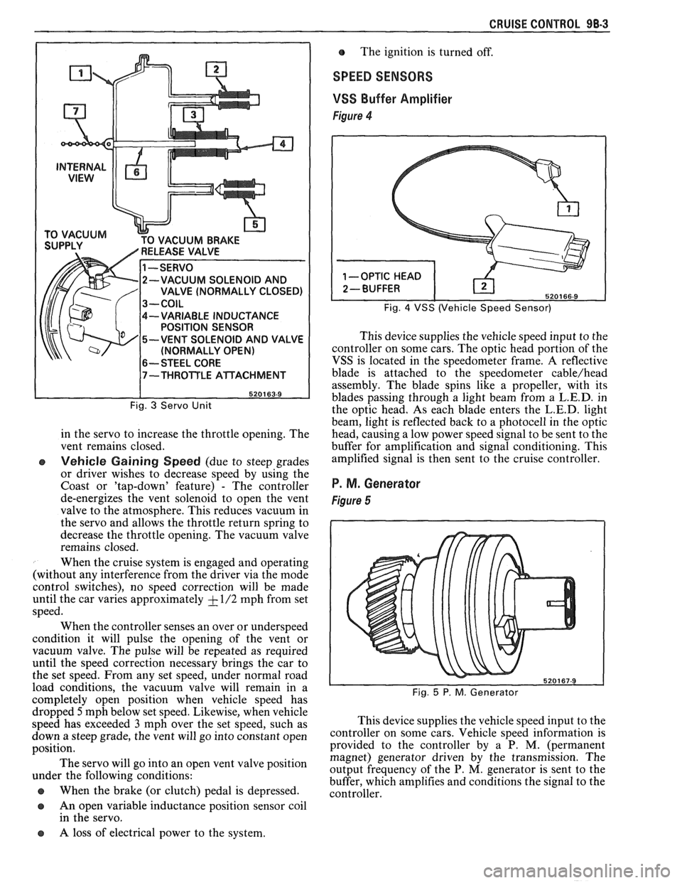
CRUISE CONTROL 98-3
CUUM BRAKE
-VARIABLE INDUCTANCE
POSITION SENSOR
-VENT SOLENOID AND VALVE
(NORMALLY OPEN)
6-- STEEL CORE
Fig. 3 Servo Unit
in the servo to increase the throttle opening. The
vent remains closed.
e Vehicle Gaining Speed (due to steep grades
or driver wishes to decrease speed by using the
Coast or 'tap-down' feature)
- The controller
de-energizes the vent solenoid to open the vent
valve to the atmosphere. This reduces vacuum in
the servo and allows the throttle return spring to
decrease the throttle opening. The vacuum valve
remains closed.
When the cruise system is engaged and operating
(without any interference from the driver via the mode
control switches), no speed correction will be made
until the car varies approximately
+ - 1/2 mph from set
speed.
When the controller senses an over or underspeed
condition it will pulse the opening of the vent or
vacuum valve. The pulse will be repeated as required
until the speed correction necessary brings the car to
the set speed. From any set speed, under normal road
load conditions, the vacuum valve will remain in a
completely open position when vehicle speed has The
ignition is turned off.
SPEED SENSORS
VSS
Buffer Amplifier
Figure 4
Fig. 4 VSS (Vehicle Speed Sensor)
This device supplies the vehicle speed input to the
controller on some cars. The optic head portion of the
VSS is located in the speedometer frame. A reflective
blade is attached to the speedometer
cable/head
assembly. The blade spins like a propeller, with its
blades passing through a light beam from a
L.E.D. in
the optic head. As each blade enters the
L.E.D. light
beam, light is reflected back to a photocell in the optic
head, causing a low power speed signal to be sent to the
buffer for amplification and signal conditioning. This
amplified signal is then sent to the cruise controller.
P. M. Generator
Figure 5
dropped 5mph below set speed. Likewise, when vehicle
speed has exceeded
3 mph over the set speed, such as This
device supplies the vehicle speed input to the
down a steep grade, the vent will go into ,-onstant open ~0ntI-011er on some cars. Vehicle speed information is
position. provided
to the controller by a P. M. (permanent
magnet) generator driven by the transmission. The
The servo go into an 'Pen vent position output frequency of the P. M, generator is sent to the under the following conditions:
buffer, which amplifies and conditions the signal to the
@ When the brake (or clutch) pedal is depressed. controller.
a An open variable inductance position sensor coil
in the servo.
a A loss of electrical power to the system.
Page 1677 of 1825
96.4 MISCELLANEOUS ACCESSORIES
DASH AND CONSOLE MOUNTED ACCESSORY
SWITCHES
Installation for various dash and console
mounted accessory switches is shown in Section
8C.
GENERAL DESCRIPIIOM
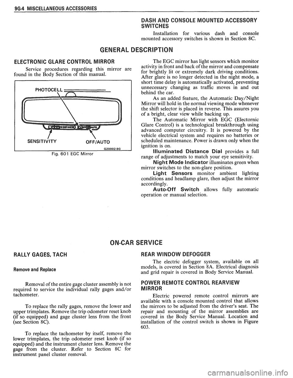
ELECTRONIC GLARE CONTROL MIRROR
Service procedures regarding this mirror are
found in the Body Section of this manual.
Fig. 601 EGC Mirror
The EGC mirror has light sensors which monitor
activity in front and back of the mirror and compensate
for brightly lit or extremely dark driving conditions.
After glare is no longer detected in the night mode, a
short time delay is automatically activated, preventing
unnecessary changing as traffic moves in and out
behind the car.
As an added feature, the Automatic
Day/Night
Mirror will hold in the normal viewing mode whenever
the shift selector is placed in reverse. This assures you
of a bright, clear view while backing up.
The Automatic Mirror with EGC (Electornic
Glare Control) is a technological breakthrough using
advanced computer circuitry. It is powered by the
vehicle electrical system and requires no batteries or
scheduled maintenance. Power is drawn only when the
ignition is on.
Illuminated Distance Dial provides a full
range of adjustments to match your eye sensitivity.
Night Mode Indicator illuminates green when
mirror switches to the non-glare position.
Light Sensors monitor ambient lighting
conditions and
headlamp glare, then adjust the mirror
accordingly.
Auto-Off Switch allows fully automatic
operation or manual selection.
ON-CAR SERVICE
RALLY GAGES, TACH REAR WINDOW DEFOGGER
Remove
and Replace
The electric defogger system, available on all
models, is covered in Section
8A. Electrical diagnosis
and grid repair is covered in Body Service Manual.
Removal of the entire gage cluster assembly is not
POWER RmOTE CONTROL REARVIEW
required to service the individual rally gages and/or MIRROR
tachometer.
Electric powered remote control mirrors are
available with a console mounted control that allows
To replace the rally gages, remove the lower and the
mirrors to be adjusted from the driver's seat. The
upper trimplates. Remove the trip odometer reset knob repair
and mounting of the mirror assemblies are
(if so equipped) and gage cluster lens from the front covered in
the Body Service Manual. Location and
(see Section
8C). installation of the control switch is shown in Figure
603.
To replace the tachometer by itself, remove the
lower trimplates, the trip odometer reset knob (if so
equipped) and the instrument cluster lens. Remove the
gage from the cluster. Refer to Section
8C for
hstrument panel cluster removal.
Page 1817 of 1825
2 - CHASSIS INDEX
Backup Lamp Switch (Circuit) .......... 8A- 1 12. 7A 1-5
Backup Lights
..................................................... 8B-1
...................................................... Battery Section 6D 1
............................ Battery Specification Chart 6D 1-7
.................................... Body Identification ... .... OA- 1
Borg Warner Rear Axle .......................... Section 4B1
...................................................... Blower Motor 1A-14
Blower Switch
.................................................... 1 A- 13
Booster Assembly
............................................. 5D2-2
Brakes
- General ......................................... Section 5
Adjustment
.................................................... 5C3-4
Booster Assembly
. Tandem
Diaphragm
................... .... ..................... 5D2- 1
................................................ Components 5C3- 1
Diagnosis and Inspection
................................. 5-3
Disc Brake Caliper Assembly
.................................................... 3548 Series 5B6-1
Drum Brake Assembly ........................ Section 5C3
General Description
.......................................... 5-2
On-Car Service
.................................................... 5-7
Specifications & Special Tools ......................... .5 F. 1
...................................................... Unit Repair 5A3- 1
.......................................... Warning System 8A-4 1-0
............ Brake Pedal Mounting .. ......................... 5-1 7
Bulb Usage Chart
............................................ 8B-10
............................................ Bumpers Section 2B,3 D.6
Bumper Energy Absorbing Units
.................... 2B-2
Bench Testing
................................................ 2B-3
........................................ Damage/Leakage 2B-3
................................ Removal After Collision 2B-2
............................................. Fascia Rub Strips .2 B. 1
.................................................... Front Bumper 2B-2
Assembly
........................................................ 2B-4
Energy Absorber
........................................... 2B-4
............................................................. Fascia .2 B. 1
On-Vehicle Service
...................................... 2B-4
Rear Bumper
.................................... .... ............ 2B-2
........................................................ Assembly 2B-5
Energy Absorber
............................................ 2B-4
............. .................... Fascia Molding Strip .. 2B-5 ........................................... Service Procedures .2 B. 1
.................................................. Specifications 2B-5
C
Caliper Assembly . Disc Brake
.............................................. 3000/3 100 Series 5B 1-2
3548 Series
...................................................... 5B6-2
Caliper Overhaul
....................... 3000/3 100 Series .. ............... 5B 1-4
3548 Series
.................................................... 5B6-5
Caster and Camber Adjustment
........................ 3A- 1
............................................. Catalytic Converter 6F-2
Center High-Mounted Stoplight
....................... ... 8B- 1
Charging System
...................... 8A.30.7, Section 6D3
Chassis Electrical
.................................... Section 8B
Center High Mounted Stoplight
...................... 8B-1 ................................. Exterior Light Monitor .8 B. 1
................................................................ Chimes 8A-77
................................ Cigar Lighter (Circuit) 8A- 1
14-0
.............................. Circuit Breaker Details Section 8A
Power ACC Circuit Breaker .... 8A- 10.1.10.3.10.5.
11-3
.... Window Circuit Breaker 8A~10~1,10~3.10~5.1 1.4
Clutch
........................................................ Section 7C
......................................... General Description .7 C. 1 ........................................................... Diagnosis 7C-2 Bleeding
Hydraulic Clutch System
................. .7 C.2
Preliminary Checks ..................................... ... 7C-2
On-Vehicle Service
........................................... 7C-5
Clutch Hydraulic System
.................................. 7C-5
Clutch Pedal ...................................................... 7C-6
Pilot Bearing
..................................................... 7C-6
Pressure Plate and Disc
.................................... 7C-6
Special Tools
......................... ....... ................ 7C-8
Specifications
................................................... 7C-8
Coil Springs and Insulators .............................. 3D-1
Component Fluid Capacities
................................ OB-6
Component Location Views
........................ 8A-201-0
Composite Master Cylinder
................... Section 5A3
Compression Test
.................. .. ............................. 6-5
Condenser Mounting
....................................... 1B 1-24
Connectors
.................................................... 8A-202-0
Coolant Fan Temperature Switch
...................... 8A-3 1
Cooling and Radiator
................................ Section 6B
Cooling System Capacities
................................. OB-6
Cooling System Diagnosis
.................................... 6B-3
Cranking System
...................................... Section 6P*
Diagnosis ..................................................... 6~2
General Description ................................ 6D2- 1
Cranking System
........................................ 6D2- 1
Solenoid
................................................... 6D2- 1
Starter Motor ......................................... 6D2-1
On-Vehcile Service
...................................... 6D2-4
Specifications
............................................ 6D2- 1
Starter
........................................................ 6D2-4
Unit Repair
............................................ 6D2-6- 11
Service Procedures
...................................... 6D2-3
Cruise Control
.............................. 8A-34-0, Section 9B
Diagnosis
............................................................ 9B-4
Cruise Set Speed High or Low
.................... 9B-4
Cruise System Surges
.................................. 9B-4
Cruise Tap-Up and Tap-Down
...................... 9B-4
Excessive Cruise Speed Loss on
Hills
........................................................... 9B-4
General Description
........................................ 9B-1
Electrical and Vacuum Release
Switches
...................................................... 9B-4
Electrical Harness
.......................................... 9B-A
Electronic Controller (Module) .................... 9B .
Off/On/Resume/Accel Switch
Operation
.................................................. .91 B-
Servo Unit
.................................................... 9B-2
Set/Coast Button Switch .............................. 9B-1
................................................ Speed Sensors 9B-3
Vacuum Supply
............................................ 9B-4
On-Car Service
.................................................. 9B-6
................................ Cruise Release Switches 9B-6
.......................................... Servo Mounting 9B-10
Vacuum Harness and Cable Routing
VIN
E ................................. .. .................. 9B,7
.................................................... VIN F, 8 9B-9
....................................................... VIN S 9B-8
........................ Vacuum Tank - VIN S,F,E, 9B-10
.............................. Cruise Control (Circuit) 8A-34-0
D
......................................... Defogger (Circuit) $A-6 1-0
..................... ...... Defroster Duct Assembly ... .812 C-
Diagnosis
Air Conditioning
- General ........................... 1B-5
.................... Automatic Transmission - General 7A
Automatic Transmission
- ................ HD-700-R4-2