Page 1553 of 1825

RADIO I
(Continued from previous page) from back of Radio
If noise persists with replacement antenna, the
problem must be repaired at the source of noise
(generator, ignition system, accessory, etc.). See
Delco Manual for noise "Sniffing" procedures.
Ignition Noise
Trv the following. fixes in the piven order: 8. Install a braided ground strap on the hood. Replace
defective antenna with a good antenna.
If noise disappears repair or replace the defective
antenna. Check antenna ground, Coaxial Cable
Braid, and ground at connectors.
unplugged
- -
1. Check
for loose or defective spark plug wire.
2. Check for defective spark plug.
3. Move all wiring away from Ignition System
and spark plug wires. Antenna
noise
4. Reroute spark plug wires laying against
anything that could possibly transmit noise
to the Radio (car
g or sensor leads that
travel into the passenger compartment).
5. Inspect Ignition system for the following
and replace if necessary:
r Distributor cap carbon ball eroded away,
cracked or loose cap.
A rotor with burned black spot on wiper or
pits in wiper surface.
r A defective coil.
r An oily film on some of the lead terminals or
inside the cap.
Defective
WE1 module; can cause ignition
noise on
FM only.
6. Replace distributor cap and rotor.
9. Check Heater Core ground; clean or install a
braided ground strap if necessary.
10. Check air conditioner accumulator ground;
clean or install a braided ground strap if
necessarv.
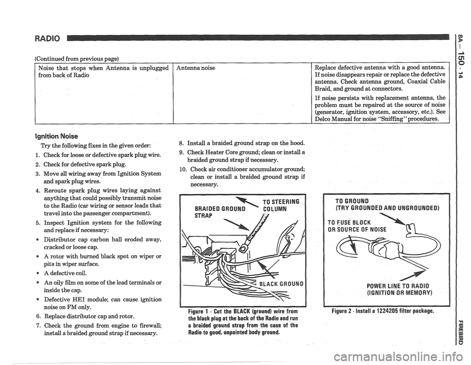
TO STEERING
BRAIDED
GROUN GO LUMN
Figure 1 - Gut the BLACK (ground) wire from
the black plug
at the back of the Radio and run
7. Check the ground from engine to firewall, a braided ground strap from the ease of the
install a braided ground strap if necessary. Radio to good, unpainted body ground.
(TRY GROUNDED AND UNGROUNDED)
POWER LlNE TO RADIO
(IGNITION OR MEMORY)
Figure 2 - install a 1224205 filter package.
Page 1561 of 1825
-. COMPONENT LOCATION VIEWS
PRESSURE WBPER MOTOR FUEL
COO LAMT CUT-OBIT MODULE
TEMPERATURE SMITGH C2
SENSOR CBSMMECTBBR
CONNECTOR
FUEL SWITCH (WITHOUT GAGES)
PUMP
SWITCH
STEERING
SWITCH
12H8.1
Figure A - LN Side Of VIN S Engine Cornpartwent
TEMPERATURE
Figglare B - Top LH Frcswt Of VIM S Engine
COLD
START
INJECTOR
Figure G - Top LN Rear Of VIN S Engine
Page 1562 of 1825
COMPONENT LOCATION VIEWS
I
MASS AI R FUELPUMP EANlSTER (MAT) SENSOR
FLOW IN-LINE IN-LBNE PURGE FAN PRESSURE
FUSE FUSE
SOLENOlD SVVlTEH
VALVE
12H7.1
- - Figure A - VIN S Engine CompaFtment
Figure B - Lower LN Front Of VIM S Engine
. SPARK TlMlNG
--
Figure C - Top LM Rear Of VlN S Engjne
Page 1563 of 1825
COMPONENT LOCATION VIEWS IS
FRo&, MANIFOLD ABSOLUTE IDLE AIR
) PRESSURE (MAP) CONTROL ELECTRONIC SPARK
SENSOR STEPPER CONTROL
(ESC)
MOTOR MODULE
CONNECTOR
I
VVASNER
S143
S172 MOTOR
S120 CONNECTOR
S174 S127
AIR SELECT
JUNCTION
A, B AND J AND DIVERTER BLOCK
VALVES FUSIBLE
LINKS
N AND K LOW
COOLANT
Figure B
- RN Front Of Radiator (Except VIN S)
Figure C - LN Side Of Radiator (VlN S)
Page 1565 of 1825
COMPONENT LOCATION VIEWS I?
MANIFOLD AIR
TEMPERATURE
h
(MAT) SENSOR
EXHAUST GAS
RECIRCULATION
(EGR) SOLENOID
IGNITION
COIL
THROTTLE POSITION
-- -
SENSOR
FUEL
INJECTORS
SWITCH COMPRESSOR
TCN
CONNECTOR
FUSIBLE (DIODE INSIDE)
LINK ti 12Hll.l
Figure A - RN Side Of VIN E Engine Compartment
STARTER
FeOlyr DETONATION
SOLENOID SENSOR
a
Figure B - RH Front Of VlN E Engine Figure
C - Lower RH Side Of VIN E Engine Figure
D - Top LN Front
Of VIN E Engine
Figure E -Top Rear Of
VIN F Engine
(VIN 8 Similar)
Page 1569 of 1825
COMPONENT LOCATION VIEWS I $
6143 COOLANT
TEMPERATURE
SENDER (WITH
GAGES) OR
SWITCH (WITHOUT
GAGES)
FUEL
1) F~oer PUMP
OF c.4 Fj SWITCH
12H21.3
Figure A - Lower LH Side Of VIN F Engine
(VIN 8 Similar)
Figure
B - Lower LH Front Of VIN F Engine
(VIN 8 Similar) THROTTLE
POSITION
START
WITCH 12H20.2
Figure C - Front Of VIN F Engine (VIM 8 Similar)
SENSOR
12H22.1
Figure D - LH Side Of Transmission (Manual
Shown, Automatic Similar) Figure
E
- Center Frcpt Of Dash
Figure
F - LN Side Of Manual Transmission
Page 1593 of 1825
HARNESS CONNECTOR FACES
BLK
MASS AIR FLOW SENSOR
(V8 WIN F) (V8 WIN 8)
V00526.2
WHT
OUTSIDE MIRROR SWITCH
V00184 2
PASSENGER'S LUMBAR CONTROL SWITCH,
SEE DRIVER'S LUMBAR CONTROL SWITCH
, PASSENGER'S LUMBAR VALVE ASSEMBLY,
1 SEE DRIVER'S LUMBAR VALVE ASSEMBLY
C2 BLK C1 CRY
RADIO (WITH SUBWOOFER)
~00320 0
C4 BLK
C1 BLK
C2 WHT
C3 BLU
RADIO (WITHOUT SUBWOOFER AND
UK3)
V00236 1
C2 BLK
(C218 WITH UK3 AND SUBWOOFER)
C4 BLU
(C217 WITH UK3 AND SUBWOOFER)
RADIO
(WITH UK3)
V00578.0
Page 1595 of 1825
HARNESS CONNECTOR FACES
C1 BLK C2 BLK
VEHICLE SPEED SENSOR BUFFER
Ct BLK CZ BLK
WIPER MOTOR MODULE
VOW09 1