1988 PONTIAC FIERO transmission
[x] Cancel search: transmissionPage 1714 of 1825
DOORS - F STYLE 5H-1
SEC"610N 5H
DOORS
NOTICE: The anit-theft label found on some major sheet metal, engines, and transmissions must be masked
prior to painting, rustproofing, undercoating, etc. The mask
must be removed following the above operations.
Failure to keep the label clean and readable may result in liability for violation of Federal Vehicle Theft Prevention
Standard, and subject the vehicle owner to possible suspicion that the part was stolen.
Door Trim
...................................................... 5H- 1
Armrest and Pull Handle .......................... 5H- 1
Mirror Remote Controls/Bezel ................... 5H- 1
Inside Handles and Cover Plates ................ 5H- 1
Lock Knob .................................... .... ........... 5H-2
Trim Panel Assemblies .............................. 5H-2
Doors ............................................................ 5H-3
Door Weatherstrip ....................................... 5H-4
Side Roof Rail Weatherstrip ....................... 5H-4
Window Belt Sealing Strips ......................... 5H-6
Insulator Pads - Optional ............................ 5H-6
Inner Panel Water Deflectors ...................... 5H-6
Door Hinge System .................................. .... 5H-7
Door Side Hinge Strap ............................... 5H-8
Body Side Hinge Strap ................................ 5H- 10
Door Window ..................... .. ................... 5H- 10
Window Sash Channel ................................. 5H- 1 1
Window Regulator and Motor .................... 5H- 1 1
Filler Assembly (at Belt) ......................... ... . 5H- 13
Up Stop ............................ .. ...................... 5H- 14
Rear Guide Channel .................................... 5H- 15
DOOR SECnONS
This section of the manual contains the service
operations necessary for the removal, installation,
adjustment and sealing of door assemblies and
individual hardware and trim components. It is divided
into three subsections:
1. DOOR TRIM
- removal and installation
procedures for all door trim items.
2. DOORS - including hinges, door and side roof
rail weatherstrip and all lock system components.
3. EXTERIOR MOLDINGS - removal and
installation of exterior door moldings. Standard Mirror
......................................... 5H- 15
........................... Remote
Control Mirrors 5H- 15
Power-Operated Outside Mirror ................. 5H-16
Spring Clips .................................................. 5H- 16
Connecting Rods and Locking Rods .......... 5H-16
Inside Remote Handle ................................ 5H- 16
......................................... Outside Handle 5H- 16
............................. Lock Cylinder Assembly 5H- 17
...................................... Door Lock Striker 5H- 17
....................................... Door Wedge Plate 5H- 18
....................................... Door Jamb Switch 5H- 19
........................ Door Hardware Lubrication 5H- 19
Hardware Attachment Thread
.................................................. Locking 5H- 19
................................... Door Lock Assembly 5H- 19
............................ Power Door Lock System 5H-20
........................ Power Door Lock Actuator 5H-20
............. .................................... Bell Crank ... 5H-20
.......................................... Exterior Moldings 5H-20
.......................................... Spoiler on Door 5H-21
.......................................... Spoiler on Body 5H-2 1
DOOR OUTSIDE MIRROR REMOTE CONTROLS
AND BEZEL
On styles with remote control door outside
mirror, the remote control mirror cable must be
disengaged from the bezel on the door trim panel to
permit trim panel removal. To disengage the remote
cable from the door trim panel, refer to Figure
2.
DOOR INSIDE HANDLES AND COVER PLATES
Door inside handles are retained by either rivets
or spring clips (Fig.
4). On styles equipped with rivet
retained handles, the rivets are covered by a screw
retained cover plate that can be removed as shown in
Figure
3.
DOOR TRIM Removal and Installation
DOOR ARMREST AND PULL HANDLE 1.
ASSEMBLIES
The armrest and pull handle is a one-piece
assembly and is secured to the door inner panel with
screws after door trim panel is installed (Fig. 1). Clips hidden
by window regulator handles (Fig,
4) can be disengaged by depressing door trim
assembly enough to permit inserting tool J-9886
or equivalent between handle and trim panel or
plastic bearing plate (Fig.
5). Then, with tool in
same plane as inside handle, push tool as
indicated to disengage clip. Pull handle inboard
The removal of the door trim panel on styles with to
remove from
s$n>le. -
door armrest and pull handle assemblies requires 2. To install window regulator handles, engage
removal of screws inserted through the assembly's base retaining clip on handle. Position handle at same
into the armrest hanger plate and removal of the screw angle as opposite side handle and press handle
at the top of the pull handle section.
outboard until clip engages regulator spindle.
Page 1736 of 1825
REAR QUARTERS - F STYLE 8H-1
SECTION 6H
REAR QUARTERS
NOTICE: The anti-theft label found on some major sheet metal, engines, and transmissions must be masked
prior to painting, rustproofing, undercoating, etc. The mask
must be removed following the above operations.
Failure to keep the label clean and readable may result in liability for violation of Federal Vehicle Theft Prevention
Standard, and subject the vehicle owner to possible suspicion that the part was stolen.
CONTENTS
Quarter Trim .................................................... 6H- 1
Lower Trim Finishing Panel ....................... 6H- 1
Body Lock Pillar Trim Finishing
Panel
., ....................................................... 6H- 1
Upper Trim Finishing Panel Insert ............. 6H- 1
....................................................... Speakers 6H- 1
Lift Window Upper Finishing
Molding
..................................................... 6H-2
....................... Upper Trim Finishing Panel 6H-2
QUARTER TRlM
QUARTER LOWER TRlM FINISHING PANEL
Removal and Installation (Fig. 1)
Remove body lock pillar finishing panel (Fig. 3).
Remove rear
seatback lock striker.
Remove retaining screw in rearward area of
quarter lower trim panel.
Remove rear screws from sill plate and carpet
retainer (Fig.
2).
Grasp quarter lower trim panel with hand; then
pull forward and down to disengage from
pinchweld flange at weatherstrip and quarter
upper trim finishing panel.
Remove seat belt through slot in trim panel.
Remove quarter lower trim finishing panel from
car by lifting up on rear portion of sill plate and
carpet retainer; then pull quarter trim rearward.
To install, place panel retaining slots under
quarter upper trim panel and apply upward
pressure to secure.
Position panel assembly to body. Thread lap and
shoulder belt through respective slots in panel.
Install attaching screws to secure panel to body.
Replace all previously removed components.
BODY LOCK PILLAR TRlM FINISHING PANEL
Removal and lnstallation (Fig. 3)
1. Remove trim panel attaching screws.
2. Using trim removing tool J-24595B, BT-7323A
or equivalent, carefully disengage nylon fasteners
that retain body lock pillar panel to quarter upper
trim finishing panel.
3. To install, reverse removal procedures. Spare
Tire Cover Trim Finishing
Panel
........................................................ 6H-3
Rear Stowage Compartment Box
Assembly
................................................... 6H-4
Luggage Shade Cover Assembly
................. 6H-4
Exterior Moldings
........................................... 6H-6
Fuel Tank Filler Door and Pocket
Assembly
....................................................... 6H-7
Spoiler Extension
............................ .. ........... 6H-7
QUARTER UPPER TRlM FINISHING PANEL
INSERT
Removal and Installation (Fig. 4)
1. Remove coat hook.
2. Grasp panel insert with hand and pull upward to
disengage retainers from cutout slots in quarter
upper trim finishing panel (Fig. 4).
3. To install, reverse removal procedures.
REAR QUARTER SPEAKERS
The rear quarter speakers are installed to a
speaker retainer. The retainer and speaker are then
attached to the quarter inner panel by screws.
Standard Speakers
Remove or Disconnect
1. Quarter upper trim finishing panel insert
2. Screws securing speaker retainer
3. Disconnect electrical
connector from speaker
4. Speaker
Install or Connect
1. Speaker to body
2. Electrical connector
3. Screws securing speaker to retainer
4. Quarter upper trim finishing panel insert
Subwoofer Speakers (2FS/FW/FX Styles)
Remove or Disconnect (Fig. 5)
1.
Quarter upper trim finishing panel insert (Fig. 4)
2. Body lock pillar trim finishing panel (Fig. 3)
3. Two rear screws from carpet retainer (Fig.
2)
4.
Quarter lower trim finishing panel
Page 1744 of 1825
REAR END - F STYLE 7H-1
SECTION 7H
REAR END
NOTICE: The anti-theft label found on some major sheet metal, engines, and transmissions must be masked
prior to painting, rustproofing, undercoating, etc. The mask
must be removed following the above operations.
Failure to keep the label clean and readable may result in liability for violation of Federal Vehicle Theft Prevention
Standard, and subject the vehicle owner to possible suspicion that the part was stolen.
CONTENTS
Moldings, Emblems and Name Plates ............ 7H- 1
Compartment Lift Window
.......................... ... 7H-2
Adjustments ........................... .. ................ 7H-2
Removal and Installation ............................. 7H-3
Removal of Lift Window Panel from
Glass
....................................................... 7H-3
Glass Replacement and Adjustment ........... 7H-5
Gas Support Assembly ............................. 7H-7
Lock Cylinder ....................... .. .............. 7H-8
REAR COMPARTMENT
The service operations for the removal,
installation, adjustment and sealing of the
compartment lift window assembly, individual
hardware components, moldings, emblems and name
plates attached to the compartment lift window or rear
end panel are contained in this section.
MOLDINGS, EMBLEMS AND NAME PLAES
The moldings, emblems and name plates used on
the rear compartment and rear end panels are adhesive
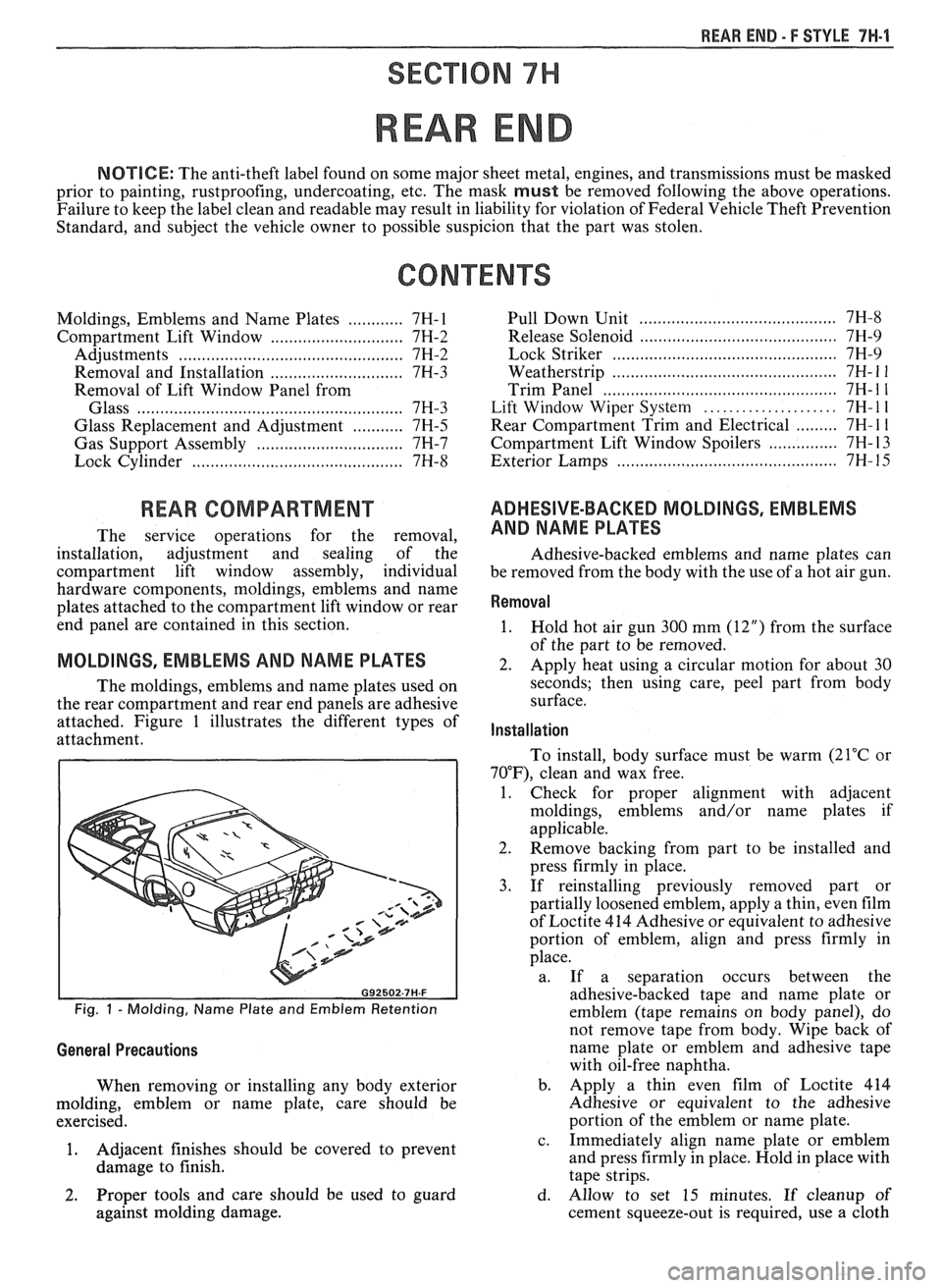
attached. Figure 1 illustrates the different types of
attachment.
Fig. 1 - Molding, Name Plate and Emblem Retention
General Precautions
When removing or installing any body exterior
molding, emblem or name plate, care should be
exercised.
1. Adjacent
finishes should be covered to prevent
damage to finish.
...................................... Pull Down Unit 7H-8
.......................................... Release Solenoid 7H-9
......... ..................................... Lock Striker ... 7H-9
................... ....................... Weatherstrip .. 7H- 1 1
.................................................. Trim Panel 7H- 1 1
..................... Lift Window Wiper System 7H- l l
......... Rear Compartment Trim and Electrical 7H- 1 1
............... Compartment Lift Window Spoilers 7H- 13
.......................................... Exterior Lamps 7H- 15
ADHESIVE-BACKED MOLDINGS, EMBLEMS
AND NAME PLATES
Adhesive-backed emblems and name plates can
be removed from the body with the use of a hot air gun.
Removal
1.
Hold hot air gun 300 mm (12") from the surface
of the part to be removed.
2. Apply heat using a circular motion for about 30
seconds; then using care, peel part from body
surface.
Installation
To install, body surface must be warm (21°C or
70"F), clean and wax free.
1. Check for proper alignment with adjacent
moldings, emblems and/or name plates if
applicable.
2. Remove backing from part to be installed and
press firmly in place.
3. If reinstalling previously removed part or
partially loosened emblem, apply a thin, even film
of Loctite 414 Adhesive or equivalent to adhesive
portion of emblem, align and press firmly in
place.
a. If a separation occurs between the
adhesive-backed tape and name plate or
emblem (tape remains on body panel), do
not remove tape from body. Wipe back of
name plate or emblem and adhesive tape
with oil-free naphtha.
b. Apply a thin even film of Loctite 414
Adhesive or equivalent to the adhesive
portion of the emblem or name plate.
c. Immediately align name plate or emblem
and press firmly in place. Hold in place with
tape strips.
2. Proper tools and care should be used to guard d. Allow to set 15 minutes. If cleanup of
against molding damage. cement squeeze-out is required, use a cloth
Page 1766 of 1825
ROOF - F STYLE 8H-7
SECTION A-A VIEW A
Fig. 8 - Lift-off Panel Opening Weatherstrip Installation
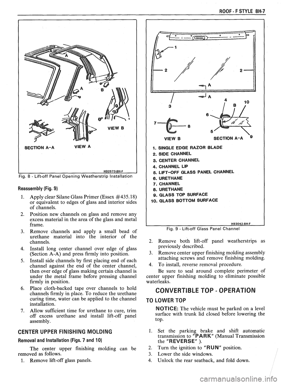
Reassembly (Fig. 9)
1. Apply clear Silane Glass Primer (Essex #435.18)
or equivalent to edges of glass and interior sides
of channels.
2. Position new channels on glass and remove any
excess material in the area of the glass and metal
frame.
3. Remove channels and apply a small bead of
urethane material into the interior of the
channels.
4. Install long center channel over edge of glass
(Section A-A) and press firmly into position.
5. Install side channels by first placing end of each
channel against the end of the center channel,
then over edge of glass making certain channel is
under the metal frame before pressing channel
firmly in position.
6. Place cloth-backed tape over channels to hold
channels firmly in place. To reduce the urethane
curing time, water can be applied to the channel
installation.
7. Allow sufficient time for urethane to cure, trim
off excess urethane and install lift-off panel
assembly.
CENTER UPPER FINISHING MOLDING
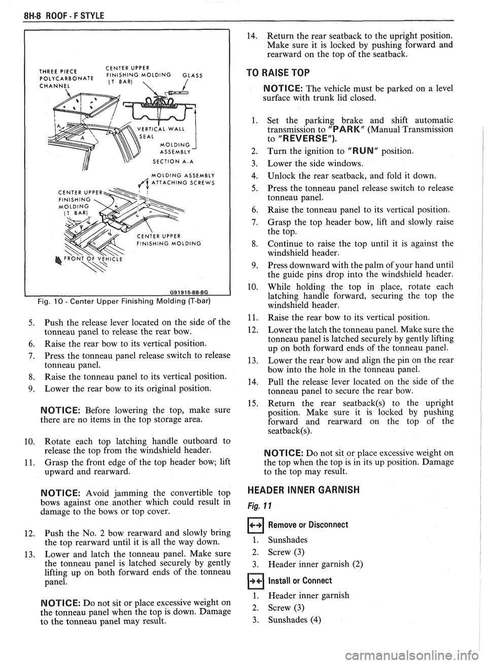
Removal and Installation (Figs. 7 and 10)
The center upper finishing molding can be
removed as follows.
1. Remove lift-off glass panels.
1 VlEWB SECTION A-A
1. SINGLE EDGE RAZOR BLADE
2. SIDE CHANNEL
3. CENTER CHANNEL
4. CHANNEL LIP
5. LIFT-OFF GLASS PANEL CHANNEL
6. URETHANE
7. CHANNEL
8. URETHANE
9. GLASS TOP SURFACE
10. GLASS BOTTOM SURFACE
Fig. 9 - Lift-off Glass Panel Channel
2. Remove both lift-off panel weatherstrips as
previously described.
3. Remove center upper finishing molding assembly
attaching screws and remove finishing molding.
4. To install, reverse removal procedure.
Be sure to seal around complete perimeter of
center upper finishing molding to eliminate possible
waterleaks.
CONVERTIBLE TOP - OPERATION
TO LOWER TOP
NOTICE: The vehicle must be parked on a level
surface with trunk lid closed before lowering the
top.
1. Set the parking brake and shift automatic
transmission to
"PARK" (Manual Transmission
the
"REVERSE" ).
2. Turn the ignition to "RUNN position.
3. Lower the side windows.
4. Unlock the rear seatback, and fold down.
Page 1767 of 1825
8H.8 ROOF - F STYLE
THREE PIECE CENTER
UPPER POLYCARBONATE FINISHING MOLDING GLASS (1 BAR)
CHANNEL 1
VERTICAL WALL
SECTION A-A
MOLDING ASSEMBLY
A ATTACHING SCREWS
Fig. 10 - Center Upper Finishing Molding (T-bar)
5. Push the release lever located on the side of the
tonneau panel to release the rear bow.
6. Raise the rear bow to its vertical position.
7. Press the tonneau panel release switch to release
tonneau panel.
8. Raise the tonneau panel to its vertical position.
9. Lower the rear bow to its original position.
NOTICE: Before lowering the top, make sure
there are no items in the top storage area.
10. Rotate
each top latching handle outboard to
release the top from the windshield header.
11. Grasp
the front edge of the top header bow; lift
upward and rearward.
N OTI C E: Avoid jamming the convertible top
bows against one another which could result in
damage to the bows or top cover.
12. Push the
No. 2 bow rearward and slowly bring
the top rearward until it is all the way down.
13. Lower
and latch the tonneau panel. Make sure
the tonneau panel is latched securely by gently
lifting up on both forward ends of the tonneau
panel.
NOTICE: Do not sit or place excessive weight on
the tonneau panel when the top is down. Damage
to the tonneau panel may result.
14. Return the rear seatback to the upright position.
Make sure it is locked by pushing forward and
rearward on the top of the seatback.
TO RAISE TOP
NOTICE: The vehicle must be parked on a level
surface with trunk lid closed.
1. Set the parking brake and shift automatic
transmission to
"PARK" (Manual Transmission
to
"REVERSE").
2. Turn the ignition to "RUN" position.
Lower the side windows.
Unlock the rear seatback, and fold it down.
Press the tonneau panel release switch to release
tonneau panel.
Raise the tonneau panel to its vertical position.
Grasp the top header bow, lift and slowly raise
the top.
Continue to raise the top until it is against the
windshield header.
Press downward with the palm of your hand until
the guide pins drop into the windshield header.
While holding the top in place, rotate each
latching handle forward, securing the top the
windshield header.
Raise the rear bow to its vertical position.
Lower the latch the tonneau panel. Make sure the
tonneau panel is latched securely by gently lifting
up on both forward ends of the tonneau panel.
Lower the rear bow and align the pin on the rear
bow into the hole in the tonneau panel.
Pull the release lever located on the side of the
tonneau panel to secure the rear bow.
Return the rear
seatback(s) to the upright
position. Make sure it is locked by pushing
forward and rearward on the top of the
seatback(s).
NOTICE: Do not sit or place excessive weight on
the top when the top is in its up position. Damage
to the top may result.
HEADER INNER GARNISH
Fig. 11
Remove or Disconnect
1. Sunshades
2. Screw (3)
3. Header inner garnish (2)
Install or Connect
1. Header inner garnish
2. Screw (3)
3. Sunshades
(4)
Page 1791 of 1825
9H-8 SEATS. F STYLE Bolt or Nut Location and Torque
6O FORWARD Many service replacement assemblies such as
OF VERTICAL front seat cushion and back frame assemblies and rear
compartment pan assembly may have unthreaded nuts
for attachment of seat adjusters,
seatback and lap belts.
Threads must be formed in these unthreaded nuts with
either the original or a new proper size thread forming
ANGLE METER bolt. Apply 67 to 89 newtons (15 to 20 pounds) of
straight-in pressure to start thread forming action of
bolt into an unthreaded nut.
NOTIICE: See NOTICE on page 9H-1 of this
section.
1. Seat adjuster-to-floor pan or adjuster-to-seat
frame bolts or nuts
- 20 to 28 N-m (15 to 21 ft-lb).
2. Front seatback outer control assembly to
seatback frame - 15 to 20 N-m (1 1 to 15 ft-lb).
3. Front
seatback frame to recliner mechanism - 20
to 28
N-m (15 to 21 ft-lb). I 4. Front seatback inner pivot hinge arm to seai
cushion frame - 20 to 28 N.m (15 to 21 ft-lb).
5. Rear folding
seatback panel pivot support to
outer bottom of
seatback - 46 N-m (34 ft-lb).
6. Rear folding
seatback lock bolt - 12 to 16 N.m
(9 to 12 ft-lb).
7. Rear folding
seatback lock striker to wheelhouse
- 46 N.m (34 ft-lb).
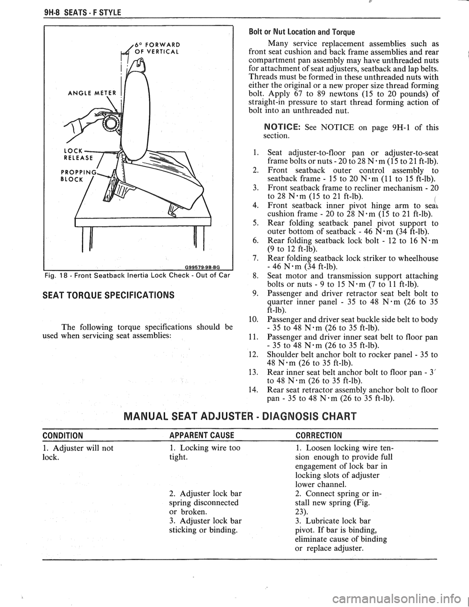
Fig. 18 - Front Seatback Inertia Lock Check - Out of Car 8. Seat
motor and transmission support attaching
bolts or nuts
- 9 to 15 N.m (7 to 11 ft-lb).
SEAT TORQUE SPECIFICATIONS 9. Passenger and driver retractor seat belt bolt to
quarter inner panel
- 35 to 48 N-m (26 to 35
ft-lb).
10. Passenger and driver seat buckle side belt to body
The following torque specifications should be
- 35 to 48 N.m (26 to 35 ft-lb).
used when servicing seat assemblies:
11. Passenger and driver inner seat belt to floor pan
- 35 to 48 N.m (26 to 35 ft-lb).
12. Shoulder belt anchor bolt to rocker panel
- 35 to
48
Nam (26 to 35 ft-lb).
13. Rear inner seat belt anchor bolt to floor pan
- 3'
to 48
Nqm (26 to 35 ft-lb).
14. Rear seat retractor assembly anchor bolt to floor
pan
- 35 to 48 N-m (26 to 35 ft-lb).
MANUAL SEAT ADJUSTER - DIAGNOSIS CHART
CONDITION APPARENTCAUSE CORRECTION
1. Adjuster will not 1. Locking wire
too
1. Loosen locking wire ten-
lock. tight. sion enough to provide full
engagement of lock bar in
locking slots of adjuster
lower channel.
2. Adjuster lock bar 2. Connect spring or
in-
spring disconnected stall new spring (Fig.
or broken. 23).
3. Adjuster lock bar 3. Lubricate lock bar
sticking or binding.
pivot. If bar is binding,
eliminate cause of binding
or replace adjuster.
Page 1793 of 1825
8'
9H-10 SEATS - F STYLE
4. One adjuster will 1. Vertical drive cable 1. Check vertical drive
not operate vertically. disconnected or damaged. cables, replace if damaged.
2. Vertical gearnut 2. Replace vertical
inoperative. actuator assembly.
5. Both adjusters will 1. Inoperative horizontal 1. See chassis manual
not operate horizon- and/or vertical solenoid Section
8A.
tally and/or verti- in transmission.
cally. 2. Damaged, broken or 2. Replace damaged, broken
inoperable solenoid or inoperable solenoid part
plunger, shaft, dog, dog
with new part.
spring, gear or drive
gear.
6. Vertical chuck or
1. Excessive clearance at
1. Grind down top of verti-
looseness. vertical
gearnut tension cal gearnut shoulder nut
spring. 0.40 to 1.19 mm
(1/64" to
3.64") maximum.
Front Seat Adjustments
Seat Adjustment at Floor Pan Attachment
A small amount of fore and aft or side adjustment
is available at the seat adjuster-to-floor pan attaching
bolts which can be used toward alignment of the seat
assembly or alignment of the seat adjusters with each
other. This adjustment can be used to help correct the
following conditions:
1. Nard or slow operation due to adjusters not being
parallel with each other.
2. Passenger side of manually operated seat must be
moved forward or rearward slightly to engage in
locked position due to one adjuster being forward
or rearward of the other.
3. Seat assembly slightly too far to right or left.
Power Six-Way Seat Adjuster Horizontal Actuator
Adjustment
With seat adjuster assembly installed on seat or
seat installed in body, horizontal movement (chucking)
can be corrected by adjusting the horizontal actuator
and pinion gear in tight to the adjuster lower track rack
gear as follows:
Adjust -
1. Operate seat to full-up position and about 3/4
full-forward position.
Loosen horizontal actuator attaching screws.
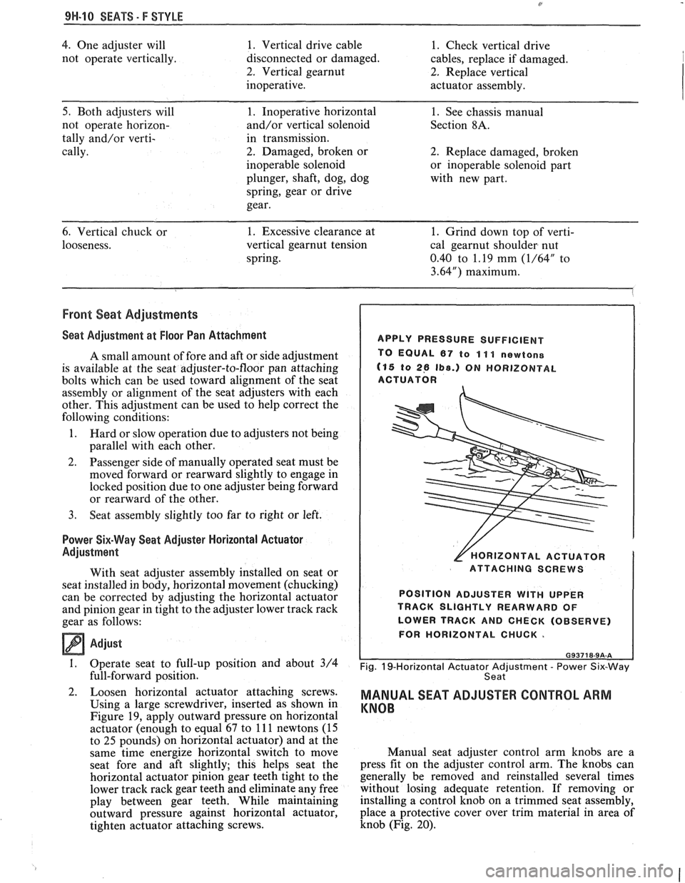
Using a large screwdriver, inserted as shown in
Figure
19, apply outward pressure on horizontal
actuator (enough to equal 67 to
11 1 newtons (15
to
25 pounds) on horizontal actuator) and at the
same time energize horizontal switch to move
seat fore and aft slightly; this helps seat the
horizontal actuator pinion gear teeth tight to the
lower track rack gear teeth and eliminate any free
play between gear teeth. While maintaining
outward pressure against horizontal actuator,
tighten actuator attaching screws.
APPLY PRESSURE SUFFICIENT
TO EQUAL
67 to 11 1 newtone
(15 to 26 Ib8.) ON HORIZONTAL
ACTUATOR
[HORIZONTAL ACTUATOR
ATTACHING SCREWS
POSITION ADJUSTER
WITH UPPER
TRACK SLIGHTLY REARWARD OF
LOWER TRACK AND CHECK (OBSERVE)
FOR HORIZONTAL CHUCK.
Fig. 19-Horizontal Actuator Adjustment - Power Six-Way
Seat
MANUAL SEAT ADJUSTER CONTROL ARM
KNOB
Manual seat adjuster control arm knobs are a
press fit on the adjuster control arm. The knobs can
generally be removed and reinstalled several times
without losing adequate retention. If removing or
installing a control knob on a trimmed seat assembly,
place a protective cover over trim material in area of
knob (Fig. 20).
Page 1817 of 1825
2 - CHASSIS INDEX
Backup Lamp Switch (Circuit) .......... 8A- 1 12. 7A 1-5
Backup Lights
..................................................... 8B-1
...................................................... Battery Section 6D 1
............................ Battery Specification Chart 6D 1-7
.................................... Body Identification ... .... OA- 1
Borg Warner Rear Axle .......................... Section 4B1
...................................................... Blower Motor 1A-14
Blower Switch
.................................................... 1 A- 13
Booster Assembly
............................................. 5D2-2
Brakes
- General ......................................... Section 5
Adjustment
.................................................... 5C3-4
Booster Assembly
. Tandem
Diaphragm
................... .... ..................... 5D2- 1
................................................ Components 5C3- 1
Diagnosis and Inspection
................................. 5-3
Disc Brake Caliper Assembly
.................................................... 3548 Series 5B6-1
Drum Brake Assembly ........................ Section 5C3
General Description
.......................................... 5-2
On-Car Service
.................................................... 5-7
Specifications & Special Tools ......................... .5 F. 1
...................................................... Unit Repair 5A3- 1
.......................................... Warning System 8A-4 1-0
............ Brake Pedal Mounting .. ......................... 5-1 7
Bulb Usage Chart
............................................ 8B-10
............................................ Bumpers Section 2B,3 D.6
Bumper Energy Absorbing Units
.................... 2B-2
Bench Testing
................................................ 2B-3
........................................ Damage/Leakage 2B-3
................................ Removal After Collision 2B-2
............................................. Fascia Rub Strips .2 B. 1
.................................................... Front Bumper 2B-2
Assembly
........................................................ 2B-4
Energy Absorber
........................................... 2B-4
............................................................. Fascia .2 B. 1
On-Vehicle Service
...................................... 2B-4
Rear Bumper
.................................... .... ............ 2B-2
........................................................ Assembly 2B-5
Energy Absorber
............................................ 2B-4
............. .................... Fascia Molding Strip .. 2B-5 ........................................... Service Procedures .2 B. 1
.................................................. Specifications 2B-5
C
Caliper Assembly . Disc Brake
.............................................. 3000/3 100 Series 5B 1-2
3548 Series
...................................................... 5B6-2
Caliper Overhaul
....................... 3000/3 100 Series .. ............... 5B 1-4
3548 Series
.................................................... 5B6-5
Caster and Camber Adjustment
........................ 3A- 1
............................................. Catalytic Converter 6F-2
Center High-Mounted Stoplight
....................... ... 8B- 1
Charging System
...................... 8A.30.7, Section 6D3
Chassis Electrical
.................................... Section 8B
Center High Mounted Stoplight
...................... 8B-1 ................................. Exterior Light Monitor .8 B. 1
................................................................ Chimes 8A-77
................................ Cigar Lighter (Circuit) 8A- 1
14-0
.............................. Circuit Breaker Details Section 8A
Power ACC Circuit Breaker .... 8A- 10.1.10.3.10.5.
11-3
.... Window Circuit Breaker 8A~10~1,10~3.10~5.1 1.4
Clutch
........................................................ Section 7C
......................................... General Description .7 C. 1 ........................................................... Diagnosis 7C-2 Bleeding
Hydraulic Clutch System
................. .7 C.2
Preliminary Checks ..................................... ... 7C-2
On-Vehicle Service
........................................... 7C-5
Clutch Hydraulic System
.................................. 7C-5
Clutch Pedal ...................................................... 7C-6
Pilot Bearing
..................................................... 7C-6
Pressure Plate and Disc
.................................... 7C-6
Special Tools
......................... ....... ................ 7C-8
Specifications
................................................... 7C-8
Coil Springs and Insulators .............................. 3D-1
Component Fluid Capacities
................................ OB-6
Component Location Views
........................ 8A-201-0
Composite Master Cylinder
................... Section 5A3
Compression Test
.................. .. ............................. 6-5
Condenser Mounting
....................................... 1B 1-24
Connectors
.................................................... 8A-202-0
Coolant Fan Temperature Switch
...................... 8A-3 1
Cooling and Radiator
................................ Section 6B
Cooling System Capacities
................................. OB-6
Cooling System Diagnosis
.................................... 6B-3
Cranking System
...................................... Section 6P*
Diagnosis ..................................................... 6~2
General Description ................................ 6D2- 1
Cranking System
........................................ 6D2- 1
Solenoid
................................................... 6D2- 1
Starter Motor ......................................... 6D2-1
On-Vehcile Service
...................................... 6D2-4
Specifications
............................................ 6D2- 1
Starter
........................................................ 6D2-4
Unit Repair
............................................ 6D2-6- 11
Service Procedures
...................................... 6D2-3
Cruise Control
.............................. 8A-34-0, Section 9B
Diagnosis
............................................................ 9B-4
Cruise Set Speed High or Low
.................... 9B-4
Cruise System Surges
.................................. 9B-4
Cruise Tap-Up and Tap-Down
...................... 9B-4
Excessive Cruise Speed Loss on
Hills
........................................................... 9B-4
General Description
........................................ 9B-1
Electrical and Vacuum Release
Switches
...................................................... 9B-4
Electrical Harness
.......................................... 9B-A
Electronic Controller (Module) .................... 9B .
Off/On/Resume/Accel Switch
Operation
.................................................. .91 B-
Servo Unit
.................................................... 9B-2
Set/Coast Button Switch .............................. 9B-1
................................................ Speed Sensors 9B-3
Vacuum Supply
............................................ 9B-4
On-Car Service
.................................................. 9B-6
................................ Cruise Release Switches 9B-6
.......................................... Servo Mounting 9B-10
Vacuum Harness and Cable Routing
VIN
E ................................. .. .................. 9B,7
.................................................... VIN F, 8 9B-9
....................................................... VIN S 9B-8
........................ Vacuum Tank - VIN S,F,E, 9B-10
.............................. Cruise Control (Circuit) 8A-34-0
D
......................................... Defogger (Circuit) $A-6 1-0
..................... ...... Defroster Duct Assembly ... .812 C-
Diagnosis
Air Conditioning
- General ........................... 1B-5
.................... Automatic Transmission - General 7A
Automatic Transmission
- ................ HD-700-R4-2