Page 1245 of 1825
MULTI-PORT FUEL INJECTION: V6 VIN S
ENGlNE DATA SENSORS, TRANSMISSION CONVERTER CLUTCH
Page 1259 of 1825
TUNED PORT INJECTION: VS VIN F
ENGINE DATA SENSORS AND TRANSMISSION CONVERTER CLUTCH
INSTRUMENT CLUSTER
PRINTED CIRCUIT
Page 1273 of 1825
THROTTLE BODY INJECTION: V8 VIN E
ENGINE DATA SENSORS AND TRANSMISSION CONVERTER CLUTCH
INSTRUMENT
CLUSTER
PRINTED
CIRCUIT
Page 1297 of 1825
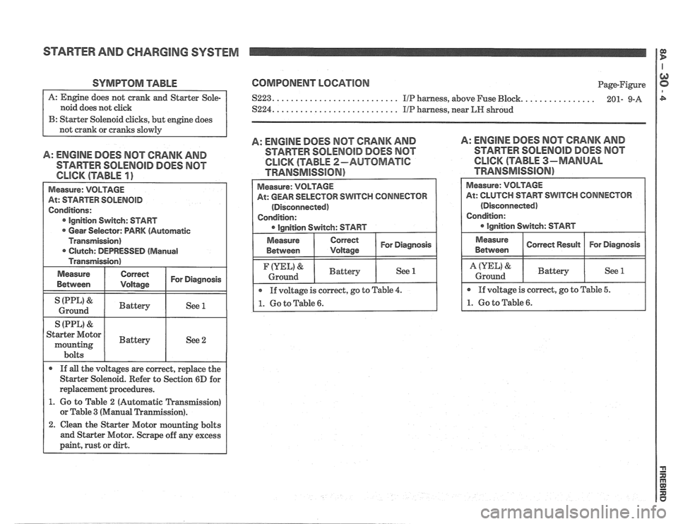
STARTER AND CHARGING SYSTEM
SYMPTOM TABLE
noid does not click
B: Starter Solenoid clicks, but engine does
A: ENGINE DOES MOT CRANK AND
STARTER SOLENOID DOES NOT
Measure: VOLTAGE
At: STARTER
SOLENOID
Conditions:
Ignition Switch: START
Gear Selector: PARK (Automatic
Transmission) Clutch: DEPRESSED
(Manual
Transmission)
Measure
Between
Correct I For Diagnosis I
I (PPL' & I Battery I See 1 I Ground
S (PPL)
& I I
Starter Motor
mounting I Battery I See 2
bolts
If
all the voltages are correct, replace the
Starter Solenoid. Refer to Section
6D for
replacement procedures.
1. Go to Table 2 (Automatic Transmission)
or Table
3 (Manual Tranmission).
2. Clean the Starter Motor mounting bolts
and Starter Motor. Scrape off any excess
paint, rust or dirt.
COMPONENT LOCATION
....... $223. .......................... IIP harness, above Fuse Bbck.
S224. .......................... IIP harness, near LIP shroud Page-Figure
........ 201- 9-A
A: ENGINE DOES MOT CRANK AND
STARTER SOLENOID DOES NOT
CLICK (TABLE 2-AUTOMATlC
TRANSMISSION)
A: ENGINE DOES MOT CRANK AND
STARTER SOLENOID DOES MOT
CLICK (TABLE 3-MANUAL
TRAMSMiSS16N)
Measure:
VOLTAGE
At: GEAR SELECTOR SWITCH CONNECTOR
(Disconnected)
Condition:
Correct 1 For Diagnosis I
If voltage is correct, go to Table 4.
1. Go to Table 6.
(YEL) &
Ground
At: CLUTCH START SWITCH CONNECTOR
(Disconnected)
Battery See 1
Page 1298 of 1825
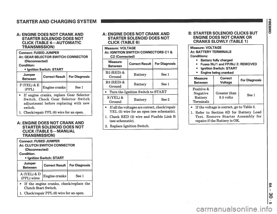
STARTER AND CHARGING SYSTEM
A: ENGINE DOES NOT CRANK AND
STARTER SOLENOID DOES NOT
CLICK (TABLE 4-AUTOMATIC
TRANSMISSION)
Connect: FUSED JUMPER
At: GEAR SELECTOR SWITCH CONNECTOR
(Disconnected)
Condition:
0 Ignition Switch: START
I
Jumper I Corren Resuk I For Diagnosis I Between
I (:::LI& IEngine cranks I See 1 1
If engine cranks, replace Gear Selector
Switch. Check Gear Selector Switch
adjustment before replacing with new
switch.
1. ChecWrepair PPL (6) wire for an open.
A: ENGINE DOES NOT CRANK AND
STARTER SOLENOlD DOES NOT
CLICK (TABLE 5-MANUAL
TRANSMISSION)
Connect: FUSED JUMPER
At: CLUTCH SWITCH CONNECTOR
(Disconnected)
Condition:
I 0 lanition Switch: START I
I :if,",":: 1 Engine cranks I See 1 I
Jumper
Between
If the engine cranks, checklreplace the
Clutch Start Switch.
1. Checklrepair PPL (6) wire for an open.
A: ENGINE DOES NOT CRANK AND B:
STARTER SOLENOID CLICKS BUT
STARTER
SOLENOID DOES NOT ENGINE DOES NOT CRANK OR
CLICK (TABLE 61 CRANKS SLOWLY (TABLE 1)
Correct Result Measure:
VOLTAGE
At: IGNITION SWITCH CONNECTORS
C1 &
C2 (Connected)
For Diagnosis
I Measure ( Correct Result I For Diagnosis 1 Between
I B2 (RED)& I Battery ( See 1 I Ground
I B3 IRED'& I Battery ( See 1 1 Ground
0 Turn the Ignition Switch to START
Measure: VOLTAGE
At: BPirTERV TERMINALS
Conditions: Battery fully charged
0 Fuses lNJ1 and FPIINJ 2: REMOVED
Ignition Switch: START
Engine being cranked
See 2 IYEL' &
Ground
For Diagnosis
See
Measure
Between
Positive &
Negative Battery
Terminals
If
all the voltages are correct, checklrepair
YEL (5) wire for an open (see schematic).
1. Check RED (2) wire and Fusible Link B
(see schematic).
2. Replace Ignition Switch.
Battery
0 If
the voltage is correct, go to Table 2.
1. Refer to Section 6D for Battery Load
Test. Remove Starter Assembly for
repairs if the Battery is
OK.
Correct
Voltage
Greater than
9.5 volts
Page 1299 of 1825
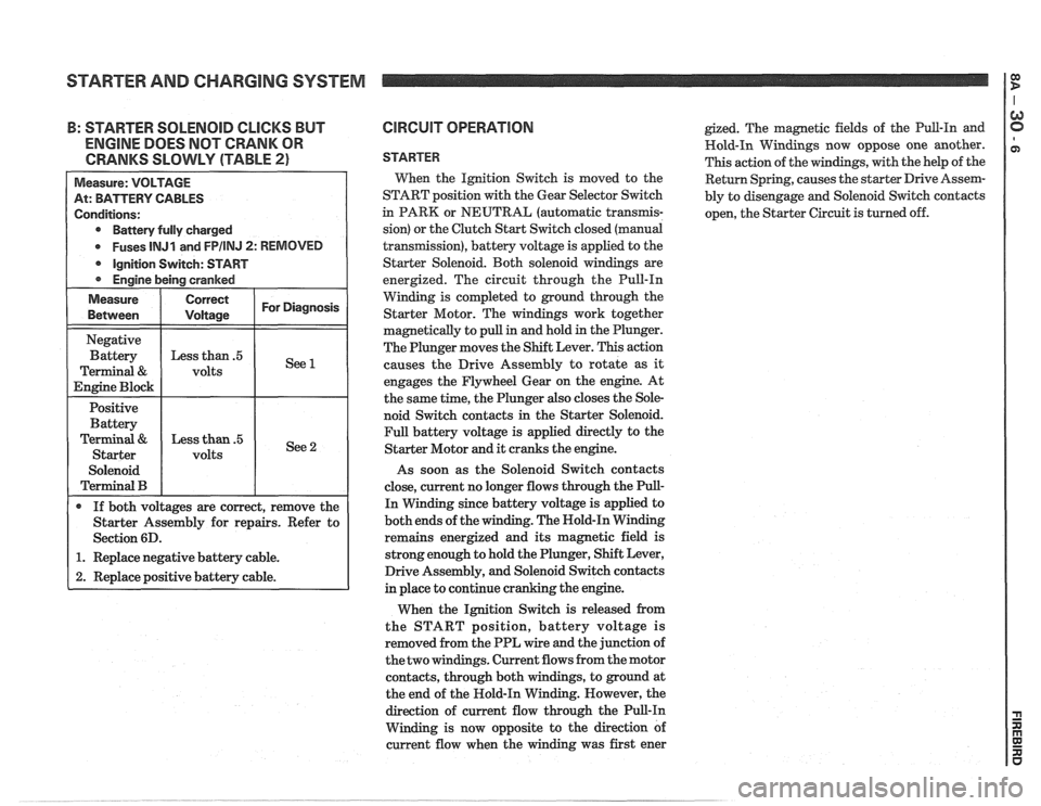
STARTER AND CHARGING SYSTEM
: STARTER SOLENOID CLICKS BUT
ENGINE DOES NOT CRANK OR
CRANKS SLOWLY (TABLE
2)
Battery fully charged
Fuses
lNJl and FPIINJ 2: REMOVED
Starter Assembly for repairs. Refer to
1. Replace negative battery cable.
2. Replace positive battery cable.
CIRCUIT OPERATION
STARTER
Wen the Ignition Switch is moved to the
START position with the Gear Selector Switch
in PARK or NEUTRAL (automatic
transrnis-
sion) or the Clutch Start Switch closed (manual
transmission), battery voltage is applied to the
Starter Solenoid. Both solenoid windings are
energized. The circuit through the Pull-In
Winding is completed to ground through the
Starter Motor. The windings work together
magnetically to pull in and hold in the Plunger.
The Plunger moves the Shift Lever. This action
causes the Drive Assembly to rotate as
it
engages the Flywheel Gear on the engine. At
the same time, the Plunger also closes the Sole-
noid Switch contacts in the Starter Solenoid.
Full battery voltage is applied directly to the
Starter Motor and it cranks the engine.
As soon as the Solenoid Switch contacts
close, current no longer flows through the Pull-
In Winding since battery voltage is applied to
both ends of the winding. The Nold-In Winding
remains energized and its magnetic field is
strong enough to hold the Plunger, Shift Lever,
Drive Assembly, and Solenoid Switch contacts
in place to continue cranking the engine.
When the Ignition Switch is released from
the START position, battery voltage is
removed from the PPL wire and the junction of
the two windings. Current flows from the motor
contacts, through both windings, to ground at
the end of the Hold-In Winding. However, the
direction of current flow through the Pull-In
Winding is now opposite to the direction of
current flow when the winding was first ener
gized. The magnetic fields of the Pull-In and
Hold-In Windings now oppose one another.
This action of the windings, with the help of the
Return Spring, causes the starter Drive Assem-
bly to disengage and Solenoid Switch contacts
open, the Starter Circuit is turned off.
Page 1318 of 1825
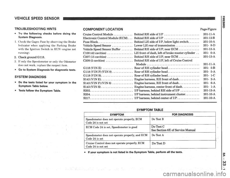
VEHICLE SPEED SENSOR
TROUBLESHOOTING HINTS
0 Try the following checks before doing the
System Diagnosis
.
1
. Check the Gages Fuse by observing the Brake
Indicator when applying the Parking Brake
wrth the Ignition Switch in RUN (engine not
running)
.
2 . Check ground 6118 .
3 . If only the Speedometer or only the Odometer
does not work. replace the suspect item
.
Go to System Diagnosis for diagnostic tests .
SYSTEM DlAGNOSlS
Do the tests listed for your symptom in the
Symptom Table below
.
Tests follow the Syrnptom Table .
COMPONENT LOCATION Page-Figure
Cruise Control Module
............ Behind RN side of IlP ...................... 201-11-A
Electronic Control Module (ECM)
... Behind RN side of IIP ...................... 201-12-B
Fuse Block
...................... Behind LN side of IIP. below light switch ....... 201-10-A
Vehicle Speed Sensor
............. Lower LEI rear of transmission ............... 201- 8-D
Vehicle Speed Sensor Buffer
....... Behind RH side of IIP. near ECM ............. 201-13-A
ClOO (42 cavities) ................ LN front of dash. left of brake master cylinder .. 201- 0-A
C207 (15 cavities) ................ Behind RH side of IIP. near ECM ............. 201-13-A
C209 (2 cavities)
................. Behind RN side of IIP. left of Cruise Control
................................. Module 201-11-A
6118 (VIN E)
................... Rear of RH cylinder head .................... 201- 5-B
6118 (VIN F) (VIN 8) ............. Rear of RN cylinder head .................... 201- 5-A
6118 (VIN S)
.................... Rear of RN cylinder head .................... 201- 1-C
S143 (VINE)
.................... Engine harness. RH front of dash ............. 201- 2-A
S143 (VIN F) (VIN
8) ............. Engine harness. RN front of dash ............. 201- 6-A
S143 (VIN S)
.................... Engine harness. center front of dash ........... 201- 1-A
S202
........................... IIP harness. behind RH side of IIP ............ 201-13-A
S204
........................... IIP harness. behind instrument cluster ......... 201-10-A
S217 ........................... IIP harness. behind center of IIP .............. 201-10-A
SYMPTOM TABLE
I SYMPTOM I FOR DIAGNOSIS I
=liter does not operate properly. ECM I Do Test B
code 24 is not set
ECM Code
24 is set. Speedometer is good
e If your symptom is not listed in the Symptom Table. pedorm all the tests .
Do Test C
See Section 6E of Service Manual
Speedometer does not operate properly. and ECM
Code
24 is set
Cruise Control does not operate properly. ECM
Code
24 is not set Do
Test
A
Do Test D
Page 1320 of 1825
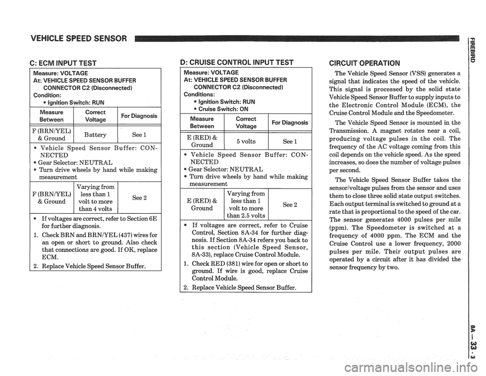
VEHICLE SPEED SENSOR
C: ECM INPUT TEST
At: VEHICLE SPEED SENSOR BUFFER
CONNECTOR
62 (Disconnected)
Gear Selector: NEUTRAL
1. Check BRN and
BRNIYEL (437) wires for
an open or short to ground. Also check
that connections are good. If
OK, replace
1 2. Replace Vehicle Speed Sensor Buffer.
At: VEHICLE SPEED SENSOR BUFFER
CONNECTOR
C2 (Disconnected)
Gear Selector: NEUTRAL
nosis. If Section 8A-34 refers you back to
this section (Vehicle Speed Sensor,
8A-33), replace Cruise Control Module.
1. Check RED (381) wire for open or short to
ground. If wire is good, replace Cruise
Control Module.
D: CRUISE CONTROL lNPUT TEST CIRCUIT OPERATION
The Vehicle Speed Sensor (VSS) generates a
signal that indicates the speed of the vehicle.
This signal is processed by the solid state
Vehicle Speed Sensor Buffer to supply inputs to
the Electronic Control Module (ECM), the
Cruise Control Module
and the Speedometer.
The Vehicle Speed Sensor is mounted in the
Transmission.
A magnet rotates near a coil,
producing voltage pulses in the coil. The
frequency of the AC voltage coming from this
coil depends on the vehicle speed. As the speed
increases, so does the number of voltage pulses
per second.
The Vehicle Speed Sensor Buffer takes the
sensorlvoltage pulses from the sensor and uses
them to close three solid state output switches.
Each output terminal is switched to ground at a
rate that is proportional to the speed of the car.
The sensor generates 4000 pulses per mile
(ppm). The Speedometer is switched at
a
frequency of 4000 ppm. The ECM and the
Cruise Control use a lower frequency, 2000
pulses per mile. Their output pulses are
operated by a circuit after it has divided the
sensor frequency by two.