1988 PONTIAC FIERO transmission
[x] Cancel search: transmissionPage 1152 of 1825
5-SPEED 77MM TRANSMISSION 78-15
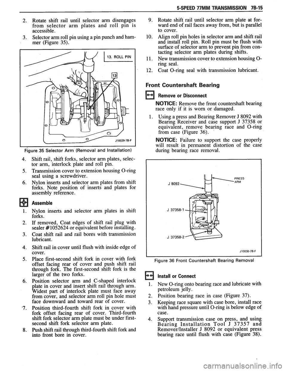
2. Rotate shift rail until selector arm disengages
from selector arm plates and roll pin is
accessible.
3. Selector arm roll pin using a pin punch and ham-
mer (Figure
35).
Figure 35 Selector Arm (Removal and Installation)
4. Shift rail, shift forks, selector arm plates, selec-
tor arm, interlock plate and roll pin.
5. Transmission cover to extension housing O-ring
seal using a screwdriver.
6. Nylon inserts and selector arm plates from shift
forks. Note position of inserts and plates for
assembly reference.
Assemble
1. Nylon inserts and selector arm plates in shift
forks.
2. If removed, Coat edges of shift rail plug with
sealer
#lo52624 or equivalent before installing.
3. Coat shift rail and rail bores with transmission
lubricant.
4. Shift rail in cover until flush with inside edge of
cover.
5. Place first-second shift fork in cover with fork
offset facing rear of cover and push shift rail
through fork. The first-second shift fork is the
larger of the two forks.
-
6. Position selector arm and C-shaped interlock
plate in cover and insert shift rail through
arm.
Widest part of interlock plate must face away
from cover, and selector
arm roll pin hole must
face downward and toward rear of cover.
'7. Position third-fourth shift fork in cover with
fork offset facing rear of cover. Third-fourth
shift fork selector
arm plate must be under first-
second shift fork selector
arm plate,
8. Push shift rail through third-fourth shift fork and
into front bore in cover.
9. Rotate shift rail until selector arm plate at for-
ward end of rail faces away from, but is parallel
to cover.
10. Align roll pin holes in selector arm and shift rail
and install roll pin. Roll pin must be flush with
surface of selector
arm to prevent pin from con-
tacting selector
arm plates during shifts.
11. New transmission cover to extension housing O-
ring seal.
12. Coat O-ring seal with transmission lubricant.
Front Countersha& Bearing
Remove or Disconnect
NOTICE: Remove the front countershaft bearing
race only if it is worn or damaged.
1. Using a press and Bearing Remover J 8092 with
Bearing Receiver and case support
J 37358 or
equivalent, remove bearing race and O-ring
from case (Figure
36). '
NOTICE: Failure to support the case properly
will result in permanent distortion of the case
during bearing race removal.
Figure 36 Front Countershaft Bearing Removal
Install or Connect
1. New O-ring onto bearing race and lubricate with
petroleum jelly.
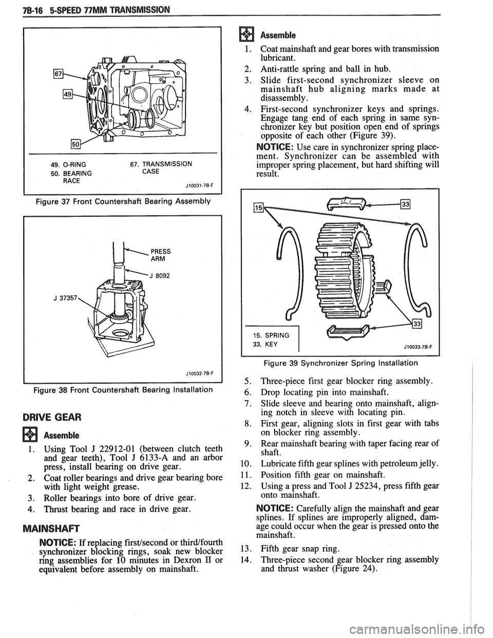
2. Position bearing race in case (Figure 37).
3. Keeping race square with case bore, install race
with hand pressure until O-ring is below edge of
case.
4. Support transmission case on press, and using
Bearing Installation Tool
J 37357 and
Remover/Installer J 8092 or equivalent press
bearing race until flush with case (Figure
38).
Page 1153 of 1825
78-16 BSPEED 77MM TMNSMISSION
49. O-RING 67. TRANSMISSION
50. BEARING CASE
Figure 37 Front Countershaft Bearing Assembly
Figure
38 Front Countershaft Bearing Installation
DRIVE GEAR
Assemble
1. Using Tool J 22912-01 (between clutch teeth
and gear teeth), Tool
J 6133-A and an arbor
press, install bearing on drive gear.
2. Coat roller bearings and drive gear bearing bore
with light weight grease.
3. Roller bearings into bore of drive gear.
4. Thrust bearing and race in drive gear.
MAINSHAm
NOTICE: If replacing firstfsecond or thirdlfourth
synchronizer blocking rings, soak new blocker
ring assemblies for 10 minutes in Dexron
I1 or
equivalent before assembly on mainshaft.
Assemble
1. Coat mainshaft and
gear bores with transmission
lubricant.
2. Anti-rattle
spring and ball in hub.
3. Slide first-second synchronizer sleeve on
mainshaft hub aligning marks made at
disassembly.
4. First-second synchronizer keys and springs.
Engage tang end of each spring in same syn-
chronizer key but position open end of springs
opposite of each other (Figure 39).
NOTICE: Use care in synchronizer spring place-
ment. Synchronizer can be assembled with
improper spring placement, but hard shifting will
result.
Figure 39 Synchronizer Spring Installation
5. Three-piece first gear blocker ring assembly.
6. Drop locating pin into mainshaft.
7. Slide sleeve and bearing onto mainshaft, align-
ing notch in sleeve with locating pin.
8. First gear, aligning slots in first gear with tabs
on blocker ring assembly.
9. Rear
mainshaft bearing with taper facing rear of
shaft.
10. Lubricate fifth gear splines with petroleum jelly.
1 1. Position fifth gear on mainshaft.
12. Using a press and Tool
J 25234, press fifth gear
onto mainshaft.
NOTICE: Carefully align the mainshaft and gear
splines. If splines are improperly aligned, dam-
age could occur when the gear is pressed onto the
mainshaft.
13. Fifth gear snap ring.
14. Three-piece
second gear blocker ring assembly
and thrust washer (Figure 24).
Page 1154 of 1825
15. Spiral snap ring,
using Tool J 37360.
16. Second gear spacer, needle bearing and gear,
aligning slots in second gear with tabs on
blocker ring assembly.
17. Second gear thrust washer and
snap ring.
18. Third
gear, spacer and needle bearing assembly.
Make sure the bearing spacer is not trapped
between the gear face and snap ring. The spacer
runs inside the gear bore.
19. Using
a press and Tool
J 37372, install
thirdtfourth synchronizer, third blocker ring and
third gear as an assembly.
Important
Before pressing components together, make
sure the synchronizer hub faces the short end of
the mainshaft. Hold third gear against the syn-
chronizer to maintain blocker ring alignment
with keys.
Assemble
1. Using a press and Bearing Installation Tools
J 37357 and J 8092 or equivalent, install front
countershaft bearing onto countershaft.
2. Position countershaft in case.
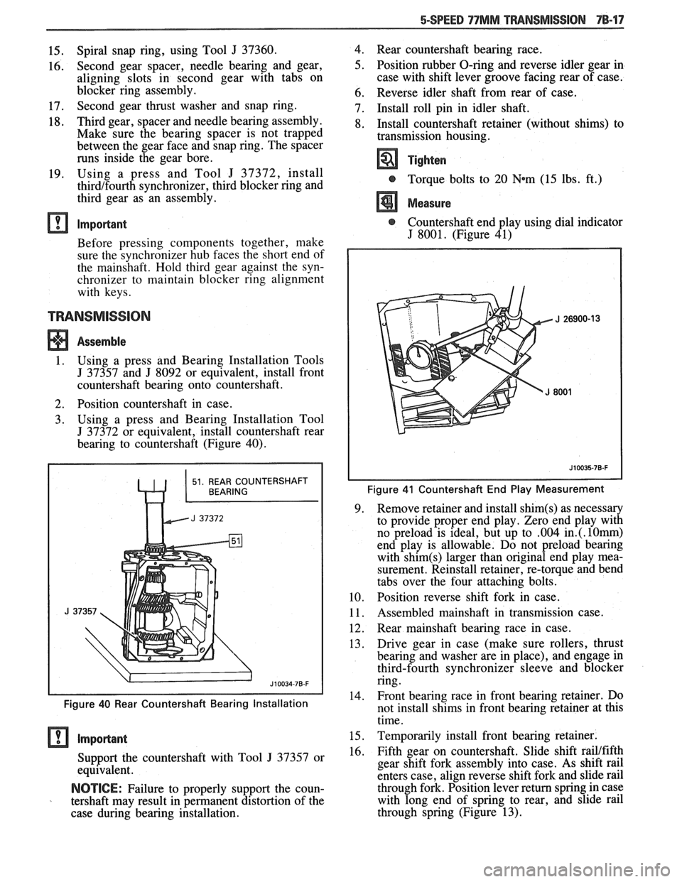
3. Using
a press and Bearing Installation Tool
J 37372 or equivalent, install countershaft rear
bearing to countershaft (Figure 40).
Figure 40 Rear Countershaft Bearing Installation
Support the countershaft with Tool J 37357 or
equivalent.
NOTICE: Failure to properly support the coun-
tershaft may result in permanent distortion of the
case during bearing installation. 4.
Rear countershaft bearing race.
5. Position rubber O-ring and reverse idler gear in
case with shift lever groove facing rear of case.
6. Reverse idler shaft from rear of case.
7. Install roll pin in idler shaft.
8. Install countershaft retainer (without shims) to
transmission housing.
Tighten
@ Torque bolts to 20 Wm (15 lbs. ft.)
Measure
@ Countershaft end play using dial indicator
J 8001. (Figure 41)
Figure 41 Countershaft End Play Measurement
9. Remove
retainer and install shim(s) as necessary
to provide proper end play. Zero end play with
no preload is ideal, but up to
.004 in.(. l0rnrn)
end play is allowable. Do not preload bearing
with
shim(s) larger than original end play mea-
surement. Reinstall retainer, re-torque and bend
tabs over the four attaching bolts.
10. Position reverse shift fork in case.
11. Assembled mainshaft
in transmission case.
12. Rear
mainshaft bearing race in case.
13. Drive gear
in case (make sure rollers, thrust
bearing and washer are in place), and engage in
third-fourth synchronizer sleeve and blocker
ring.
-
14. Front bearing race in
front bearing retainer. Do
not install shims in front bearing retainer at this
time.
15. Temporarily install front bearing retainer.
16. Fifth gear on countershaft. Slide shift railtfifth
gear shift fork assembly into case. As shift rail
enters case, align reverse shift fork and slide rail
through fork. Position lever return spring in case
with long end of spring to rear, and slide rail
through spring (Figure 13).
Page 1155 of 1825
78-18 5-SPEED 77MM TRANSMISSION
Blocker ring and fifth gear synchronizer in fifth
gear shift fork. Slide fork rail assembly and syn-
chronizer into position. (Figure 20)
Fifth gear synchronizer retainer and snap ring
(Figure 12).
Oiling funnel into rear of countershaft (Figure
9)
Position fifthlreverse shift lever in case.
Connect lever return spring to front of case.
Make sure reverse shift fork pin and fifth gear
shift rail pin are engaged with shift lever and
install fifth
gearlreverse lever, pivot bolt and
retaining clip. Coat pivot bolt threads with pipe
thread sealant
#lo52080 or equivalent.
Reverse lamp switch. Coat threads with pipe
thread sealant
# 1052080 or equivalent.
Speedometer gear and retaining clip.
Circlip.
Apply 3mm
(118in.) bead of RTV Sealant,
# 105275 1 or equivalent, to transmission cover
assembly.
Make sure all synchronizers are in the neutral
position and that the shift forks in the cover are
in the neutral (center) position. Lower cover
onto case while aligning shift forks and synchro-
nizer sleeves.
Center cover and install two dowel bolts.
Remaining cover bolts.
Tighten
@ Torque all cover bolts to 14 N*m (10 lbs.
ft.).
Apply 3mm (118 in.) bead of RTV Sealant,
#I05275 1 or equivalent, to extension housing
mating surface.
Coat detent spring with petroleum jelly and
insert in offset lever. Lubricate detent plate and
install detent ball in neutral position on plate.
Position offset lever in extension housing with
spring over detent ball. Slide lever and exten-
sion housing into position as an assembly.
Extension housing vent.
Press downward on offset lever to compress
detent spring and push lever and housing into
position.
Extension housing bolts. Apply pipe thread
sealant
#lo52080 or equivalent to threads of
top two bolts.
Tighten
@ Torque extension housing bolts to 30 Nm
(23 lbs. ft.)
Align and install roll pin in offset lever and shift
rail. 35. Damper
sleeve in offset lever.
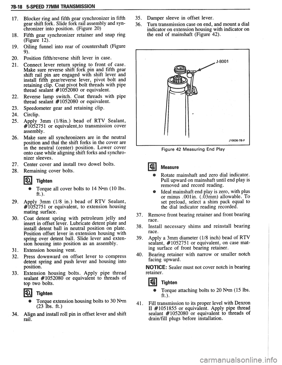
36. Turn transmission case on end, and mount a dial
indicator on extension housing with indicator on
the end of mainshaft (Figure 42).
Figure 42 Measuring End Play
Measure
@ Rotate mainshaft and zero dial indicator.
Pull upward on mainshaft until end play is
removed and record reading.
@ Ideal mainshaft end play is zero, with plus
or minus
.001in. (.03mm) allowable. To
set preload, select a shim pack equal to
the dial indicator reading recorded.
37. Remove
front bearing retainer and front bearing
race.
38. Install
necessary shims and reinstall bearing
race.
39. Apply
a 3mm diameter
(118 inch) bead of RTV
sealant,
#lo5275 1 or equivalent, on case mat-
ing surface of front bearing retainer.
40. Bearing retainer with narrow
or smaller notch
facing upward.
NOICE: Sealer must not cover notch in bearing
retainer.
Tighten
@ Torque attaching bolts to 20 N*m (15 lbs.
ft.).
41. Fill transmission to its proper level with
Dexron
I1 #I05 1855
or equivalent. Apply pipe thread
sealant
#lo52080 or equivalent to threads of
drainlfill plugs before installation.
Page 1156 of 1825
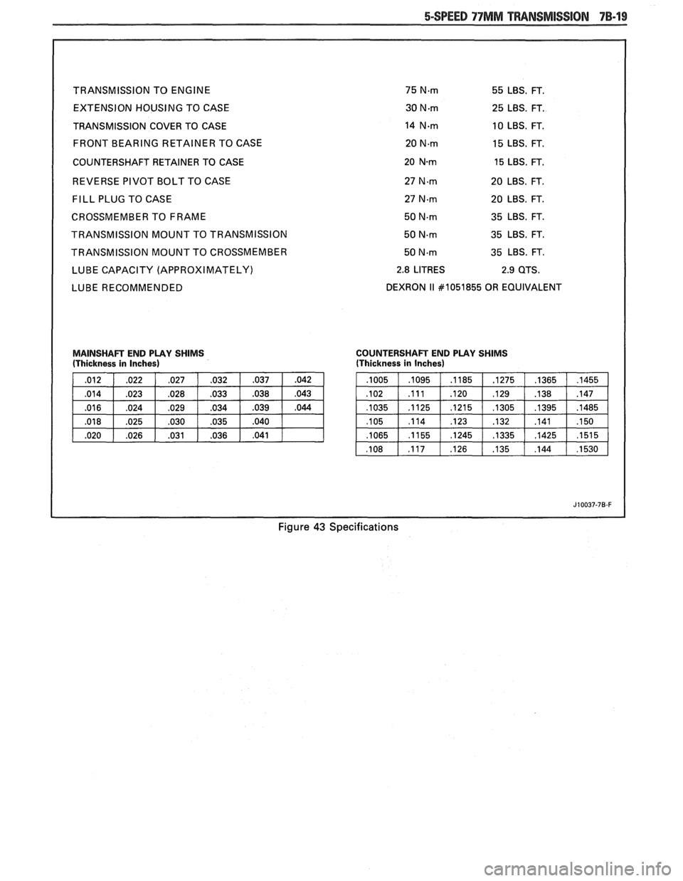
TRANSMISSION TO ENGINE 75 Nm 55 LBS. FT.
EXTENSION HOUSING TO CASE 30 N.rn 25 LBS. FT.
TRANSMISSION COVER TO CASE
14 N-rn 10 LBS. FT.
FRONT BEARING RETAINER TO CASE 20
Nm 15 LBS. FT.
COUNTERSHAFT RETAINER TO CASE
20 N.m 15 LBS. FT.
REVERSE PIVOT BOLT TO CASE 27
N.m 20 LBS. FT.
FILL PLUG TO CASE 27 N.m 20 LBS. FT.
CROSSMEMBER TO FRAME 50
N.m 35 LBS. FT.
TRANSMISSION MOUNT TO TRANSMISSION 50
N.m 35 LBS. FT.
TRANSMISSION MOUNT TO CROSSMEMBER 50
Nm 35 LBS. FT.
LUBE CAPACITY (APPROXIMATELY)
2.8 LITRES
LUBE RECOMMENDED DEXRON 11 #I051855 OR
EQUIVALENT
MAINSHAR END PLAY SHIMS COUNTERSHAFT
END PLAY SHIMS (Thickness in Inches) (Thickness
in Inches)
Figure 43 Specifications
Page 1159 of 1825
7C-2 CLUTCH
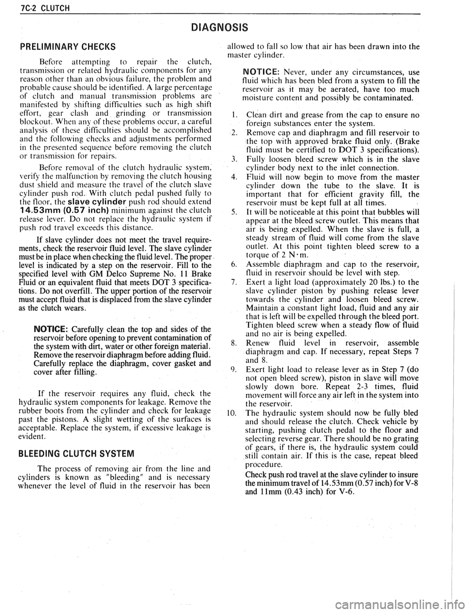
PRELIMINARY CHECKS
Before attempting to repair the clutch,
transmission or related hydraulic components for any
reason other than
an obvious failure, the problem and
probable cause should be identified.
A large percentage
of clutch and manual transmission
problenls are
manifested by shifting difficulties such as high shift
effort, gear clash and grinding or transmission
blockout. When any of these problems occur, a careful
analysis of these difficulties should be accomplished
and the following checks and adjustments performed
in the presented sequence before removing the clutch
or transmission for repairs.
Before
removal of the clutch hydraulic system,
verify the malfunction by renloving the clutch housing
dust shield and
measure the travel of the clutch slave
cylinder push rod. With clutch pedal pushed fully to
the floor, the
slave cylinder push rod should extend
14.53mm (0.57 inch) minimum against the clutch
release lever. Do
not replace the hydraulic system if
push rod travel exceeds this distance.
If slave cylinder does not meet the travel require-
ments, check the reservoir fluid level. The slave cylinder
must be in place when checking the fluid level. The proper
level is indicated by a step on the reservoir. Fill to the
specified level with
GM Delco Supreme No. 11 Brake
Fluid or an equivalent fluid that meets DOT
3 specifica-
tions. Do not overfill. The upper portion of the reservoir
must accept fluid that is displaced from the slave cylinder
as the clutch wears.
NOTICE: Carefully clean the top and sides of the
reservoir before opening to prevent contamination of
the system with dirt, water or other foreign material.
Remove the reservoir diaphragm before adding fluid.
Carefully replace the diaphragm, cover gasket and
cover after filling.
If the reservoir requires any fluid, check the
hydraulic system components for leakage. Remove the
rubber boots from the cylinder and check for leakage
past the pistons. A slight wetting of the surfaces is
acceptable. Replace the system, if excessive leakage is
evident.
BLEEDING CLUTCH SYSTEM
allowed to fall so low that air has been drawn into the
master cylinder.
NOTICE: Never, under any circumstances, use
fluid which has been bled from a system to fill the
reservoir as it may be aerated, have too much
moisture content and possibly be contaminated.
Clean dirt and grease from the cap to ensure no
foreign substances enter the system.
Remove cap and diaphragm and
fill reservoir to
the top with approved brake fluid only. (Brake
fluid must be certified to DOT 3 specifications).
Fully loosen bleed screw which is in the slave
cylinder body next to the inlet connection.
Fluid will now begin to move from the master
cylinder down the tube to the slave. It is
important that for efficient gravity
fill, the
reservoir must be kept full at all times.
It will be noticeable at this point that bubbles will
appear at the bleed screw outlet. This means that
air is being expelled. When the slave is full, a
steady stream of fluid will come from the slave
outlet. At this point tighten bleed screw to a
torque of 2
N .m.
Assemble diaphragm and cap to the reservoir,
fluid in reservoir should be level with step.
Exert a light load (approximately 20 lbs.) to the
slave cylinder piston by pushing release lever
towards the cylinder and loosen bleed screw.
Maintain a constant light load, fluid and any air
that is left will be expelled through the bleed port.
Tighten bleed screw when a steady flow of fluid
and no air is being expelled.
Renew fluid level in reservoir, assemble
diaphragm and cap. If necessary, repeat Steps
7
and 8.
Exert light load to release lever as in Step 7 (do
not open bleed screw), piston in slave will move
slowly down bore. Repeat 2-3 times, fluid
n~oven~ent will force any air left in the system into
the reservoir.
The hydraulic system should now be fully bled
and should release the clutch. Check vehicle by
starting, pushing clutch pedal to the floor and
selecting reverse gear. There should be no grating
of gears, if there is, the hydraulic system could
still contain air. If this is the case, repeat bleed
The process of removing air from the
line and procedure.
cylinders is known as "bleeding" and is necessary Check push rod travel at the
slave cylinder to insure
whenever the level of fluid in the reservoir has been the minimum travel
of
14.53mm (0.57 inch) for V-8
and 1 lrnm (0.43 inch) for V-6.
Page 1162 of 1825
CLUTCH 7C-5
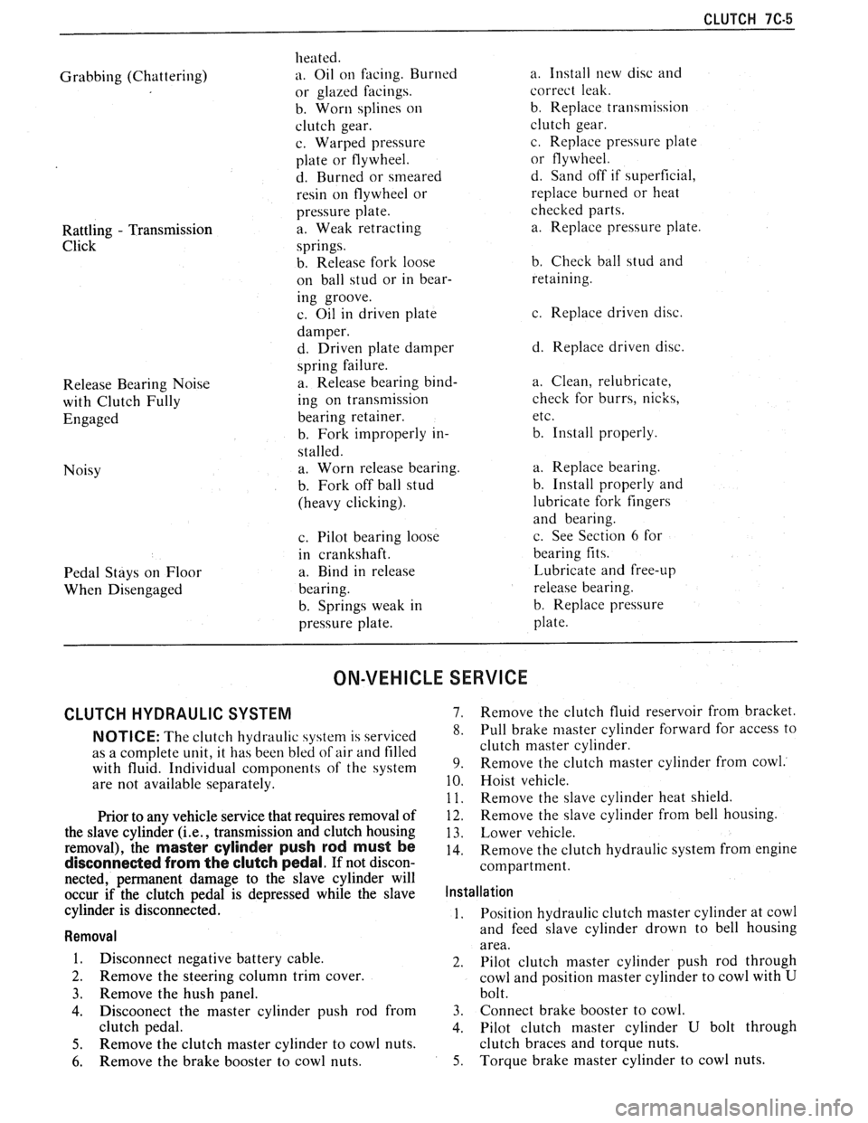
Grabbing (Chattering)
Rattling
- Transmission
Click
Release Bearing Noise
with Clutch Fully
Engaged
Noisy
Pedal Stays on Floor
When Disengaged heated.
a. Oil
on facing. Burned
or glazed facings.
b. Worn splines
on
clutch gear.
c. Warped pressure
plate or flywheel.
d. Burned or smeared
resin on flywheel or
pressure plate.
a. Weak retracting
springs.
b. Release fork loose
on ball stud or in bear-
ing groove.
c. Oil in driven plate
damper.
d. Driven plate damper
spring failure.
a. Release bearing bind-
ing on transmission
bearing retainer.
b. Fork improperly in-
stalled. a. Worn release bearing.
b. Fork off ball stud
(heavy clicking).
c. Pilot bearing loose
in crankshaft.
a. Bind in release
bearing.
b. Springs weak in
pressure plate. a.
Install new disc and
correct leak.
b. Replace transmission
clutch gear.
c. Replace pressure plate
or flywheel.
d. Sand off if superficial,
replace burned or heat
checked parts.
a. Replace pressure plate.
b. Check ball stud and
retaining.
c. Replace driven disc.
d. Replace driven disc.
a. Clean, relubricate,
check for burrs, nicks,
etc.
b. Install properly.
a. Replace bearing.
b. Install properly and
lubricate fork fingers
and bearing.
c. See Section
6 for
bearing fits.
Lubricate and free-up
release bearing.
b. Replace pressure
plate.
ON-VEHICLE SERVICE
CLUTCH HYDRAULIC SYSTEM 7. Remove the clutch fluid reservoir from bracket.
NOTICE: The clutch hydraul~c 4ystern is serviced 8. Pull brake niaster cylinder forward for access to
as a complete unit, it has been bled
of air and filled clutch master cylinder.
with fluid. Individual components of the system 9. Remove the clutch master cylinder from cowl.
are
not available separately. 10. Hoist vehicle.
1 1. Remove the slave cvlinder heat shield.
Prior to any vehicle service that requires removal of
the slave cylinder
(i.e., transmission and clutch housing
removal), the
master cylinder push rod must be
disconnected from the clutch pedal. If not discon-
nected, permanent damage to the slave cylinder will
occur if the clutch pedal is depressed while the slave
cylinder is disconnected.
Removal
1. Disconnect negative battery cable.
2. Remove the steering column trim cover.
3. Remove the hush panel.
4. Discoonect the master cylinder push rod from
clutch pedal.
5. Remove the clutch master cylinder to cowl nuts.
6. Remove the brake booster to cowl nuts.
12. Remove the slave cylinder from bell housing.
13. Lower vehicle.
14. Remove the clutch hydraulic system from engine
compartment.
Installation
1. Position
hydraulic clutch master cylinder at cowl
and feed slave cylinder drown to bell housing
area.
2. Pilot clutch master cylinder push rod through
cowl and position master cylinder to cowl with
U
bolt.
3. Connect brake booster to cowl.
4. Pilot clutch master cylinder
U bolt through
clutch braces and torque nuts.
5. Torque brake master cylinder to cowl nuts.
Page 1163 of 1825
7C-6 CLUTCH
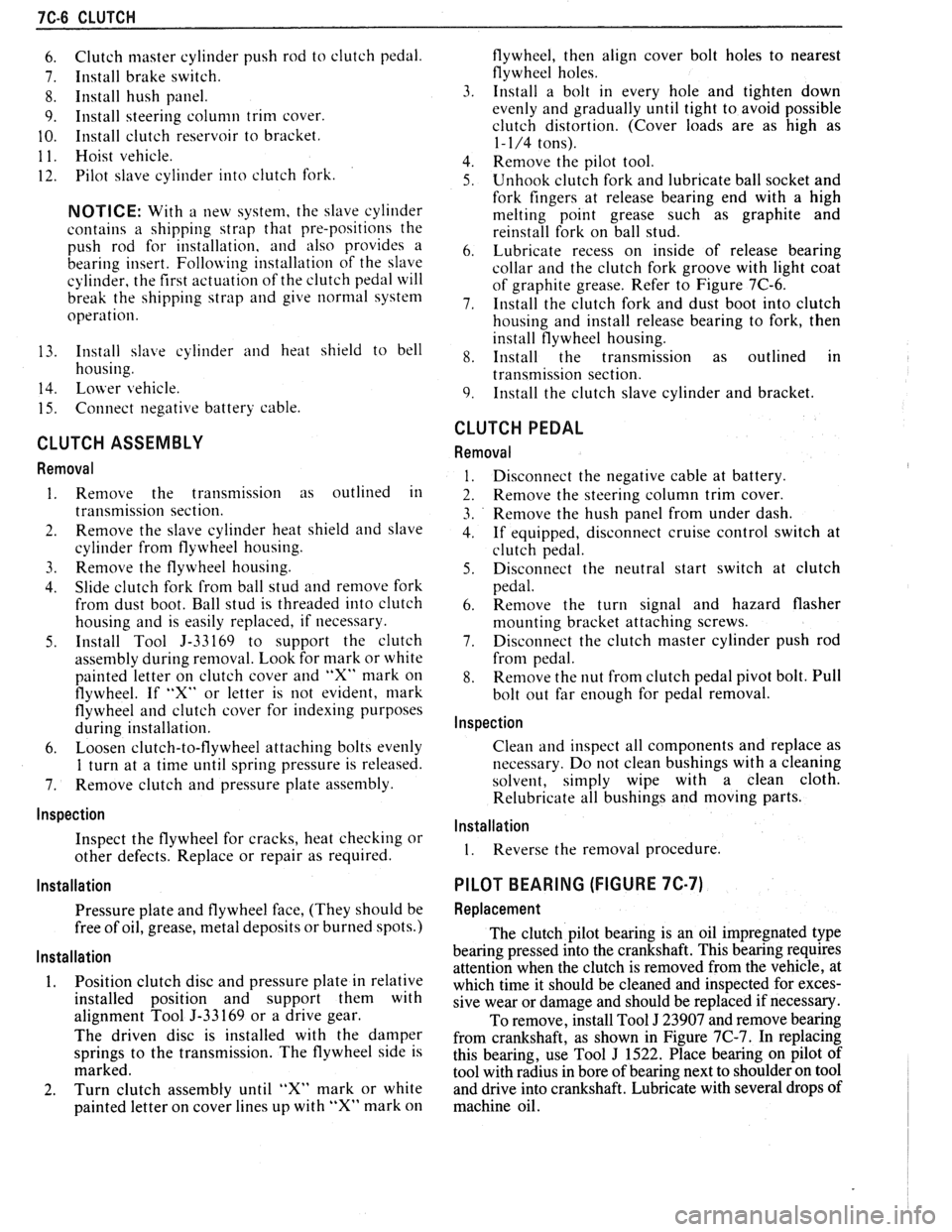
6. Clutch master cylinder push rod to clutch pedal.
7. Install brake switch.
8. Install hush panel.
9. Install steering column trim cover.
10. Install clutch reservoir to bracket.
1 1. Hoist vehicle.
12. Pilot slave cylinder into clutch fork.
NOTICE: With a new system, the slave cylinder
contains a shipping strap that pre-positions the
push rod for installation, and also provides a
bearing insert.
Follojving installation of the slave
cylinder, the first actuation of the clutch pedal will
break the shipping strap and give
normal system
operation.
13. Install slave cylinder and heat shield to bell
housing.
14.
Lojver vehicle.
15. Connect negative battery cable.
CLUTCH ASSEMBLY
Removal
1. Remove the transmission as outlined in
transmission section.
2. Remove the slave cylinder heat shield and slave
cylinder
from flywheel housing.
3. Reniove the flywheel housing.
4. Slide clutch fork from ball stud and remove fork
from dust boot. Ball stud is threaded into clutch
housing and is easily replaced, if necessary.
5. Install Tool 5-33169 to support the clutch
assen~bly during removal. Look for mark or white
painted letter on clutch cover and
"X" mark on
flywheel. If
"Xu or letter is not evident, mark
flywheel and clutch cover for indexing purposes
during installation.
6. Loosen clutch-to-flywheel attaching bolts evenly
1 turn at a time until spring pressure is released.
7. Remove clutch and pressure plate assembly.
lnspection
Inspect the flywheel for cracks, heat checking or
other defects. Replace or repair as required.
Installation
Pressure plate and flywheel face, (They should be
free of oil, grease, metal deposits or burned spots.)
Installation
1. Position clutch disc and pressure plate in relative
installed position and support them with
alignment Tool J-33169 or a drive gear.
The driven disc is installed with the damper
springs to the transmission. The flywheel side is
marked.
2. Turn clutch assembly until "X" mark or white
painted letter on cover lines up with
"X" mark on flywheel,
then align cover bolt holes to nearest
flywheel holes.
3. Install a bolt in every hole and tighten down
evenly and gradually until tight to avoid possible
clutch distortion. (Cover loads are as high as
1- 1/4 tons).
4. Remove the pilot tool.
5. Unhook clutch fork and lubricate ball socket and
fork fingers at release bearing end with a high
melting point grease such as graphite and
reinstall fork on ball stud.
6. Lubricate recess on inside of release bearing
collar and the clutch fork groove with light coat
of graphite grease. Refer to Figure 7C-6.
7. Install the clutch fork and dust boot into clutch
housing and install release bearing to fork, then
install flywheel housing.
8. Install the transmission as outlined in
transmission section.
9. Install the clutch slave cylinder and bracket.
CLUTCH PEDAL
Removal
Disconnect the negative cable at battery.
Remove the steering column trim cover.
Remove the hush panel from under dash.
If equipped, disconnect cruise control switch at
clutch pedal.
Disconnect the neutral start switch at clutch
pedal.
Renlove the turn signal and hazard flasher
mounting bracket attaching screws.
Disconnect the clutch master cylinder push rod
from pedal.
Remove the nut from clutch pedal pivot bolt. Pull
bolt out far enough for pedal removal.
Inspection
Clean and inspect all components and replace as
necessary. Do not clean bushings with a cleaning
solvent, simply wipe with a clean cloth.
Relubricate all bushings and moving parts.
Installation
1. Reverse the removal procedure.
PILOT BEARING (FIGURE 7C-7)
Replacement
The clutch pilot bearing is an oil impregnated type
bearing pressed into the crankshaft. This bearing requires
attention when the clutch is removed from the vehicle, at
which time it should be cleaned and inspected for exces-
sive wear or damage and should be replaced if necessary.
To remove, install Tool
J 23907 and remove bearing
from crankshaft, as shown in Figure
7C-7. In replacing
this bearing, use Tool
J 1522. Place bearing on pilot of
tool with radius in bore of bearing next to shoulder on tool
and drive into crankshaft. Lubricate with several drops of
machine oil.