1988 PONTIAC FIERO transmission
[x] Cancel search: transmissionPage 1327 of 1825
CRUISE CONTROL
(Continued from previous page)
TEST I: RIA CIRCUIT OPEN
Disconnect C223 and check switch continuity
between terminals A (BLU) and C (YEL) of the
pin half of the Cruise Switch in RIA.
0 If the switch is open, replace the Multi-Func-
tion Lever.
If the switch is not open, check for an open in
the
GRYIBLK (87) wire between terminal C
of connector C223 at terminal M of the Mod-
ule.
TEST J: VENT CIRCUIT SHORT
Remove the connector from the Servo and mea-
sure resistance between terminals
A and C of
the Servo.
If it is less than 30 ohms, replace the Servo.
If it is 30 ohms or more, check for a short to
ground in the DK
BLUIWHT wire from ter-
minal C of the Module to terminal A of the
Servo.
TEST K: VSS ClRCUlT OPEN
If the VSS light does not come on, or the volt-
age between terminals A (GRY) and D (BRN)
remains less than 7 volts, check for an open in
the BRN (437) wire or the RED (381) wire from
the Vehicle Speed Sensor Buffer. Refer to page
33-0 for diagnosis of Vehicle Speed Sensor.
TEST L: VSS CIRCUIT SHORT
If the VSS lights does not go off or Battery
voltage remains between ter
and D
(BRN), check for a short to ground on the
BRN (437) wire or the RED (381) wire from the
Vehicle Speed Sensor Buffer. Refer to page 33-0
for diagnosis of Vehicle Speed Sensor.
TEST M: VACUUM SYSTEM
1. Check for a blocked or leaking vacuum
source.
2. If the vacuum source is good, plug the Vac-
uum Release Port and repeat Test
6 of the
Isolation Test.
If the vacuum now holds the throttle open,
replace or repair the Vacuum Release Valve
or the hose to it.
If the test still fails, replace the Cruise Con-
trol Servo.
TEST N: SPS CIRCUIT SHORT
Disconnect the Cruise Control Servo connector
and repeat Test 7 of the Isolation Test.
If the resistance is now over range, replace
the Cruise Control Servo.
If the resistance is still low, find and repair
the short in the TAN wire from terminal F of
the Cruise Control Module to terminal B of
the Cruise Control Servo.
ClRCUlT OPERATION
The Cruise Control System operates a
mechanical linkage to the throttle by means of a
Vacuum Motor. This is a diaphragm moved by
a vacuum applied to one side. A solenoid oper-
ated valve connects the Vacuum Motor to a
Vacuum Tank. Another solenoid valve vents
the vacuum to reduce the suction. The Cruise
Control Module controls the Vacuum Motor
and the throttle by pulsing these solenoid
valves on and off.
One input to the Module is the vehicle speed.
This input comes from the Vehicle Speed Sen-
sor. If the actual speed signal is different from
the speed that was set into and remembered by
the Module, the Module generates pulses to
change the vacuum and return the vehicle to
the set speed. The Vehicle Speed Sensor is
mounted on the Transmission. Other inputs to
the Module are from the Cruise Switch and the
Set Switch. A disengage input to the Module
comes from a switch on the brake pedal. A
sepe-
rate vacuum shut down of the Cruise Control
comes from the Vacuum Release Valve on the
brake pedal.
The two outputs of the Cruise Control Mod-
ule operate the coils of the Vacuum Valve and
the Vent Valve. Both valves are located in the
Cruise Control Servo. These valves move the
throttle be means of the Vacuum Motor. The
Servo Position Sensor
(SPS) coil senses the
position and motion of the Vacuum Motor. It
feeds this information back to the Module to
provide smooth acceleration while the vehicle is
in Cruise Control.
Page 1412 of 1825
INSTRUMENT PANEL: GAGES CLUSTER
Speedorneter and Odometers
The Speedometer is operated by an electronic
circuit. The Vehicle Speed Sensor (VSS),
located in the transmission, generates an AC
voltage whose frequency is proportional to the
speed of the vehicle. This goes to the Vehicle
Speed Sensor Buffer and then to the Speedom-
eter circuit board in the Instrument Cluster.
The Solid State circuit drives the pointer of the
Speedometer. There is no speedometer cable
in
the vehicle.
The same speed signal from the Vehicle Speed
Buffer is processed by the Speedometer circuit
board to drive the Odometers. They are oper-
ated by a motor that responds to pulses from
the Speedometer circuit.
UpshiN Indicator
With Manual Transmission, the indicator
lights when the car should be shifted to the next
higher gear for better fuel economy. Battery
voltage is applied to one side of the bulb. The
other side of the bulb is switched to ground by
the ECM which uses engine data to compute an
efficient shift point.
Page 1428 of 1825
INSTRUMENT PANEL: DIGITAL CLUSTER n 23 rn E
ClRCUlT OPERATION
The Instrument Cluster uses a microprocessor
to develop data for fuel supply, coolant tem-
perature, oil pressure, voltage, engine rpm, and
vehicle speed. The Digital Cluster also contains
an Odometer, Warning Indicators, and an Audi-
ble Alarm. The Audible Alarm signals low oil
pressure, high temperature, low or high voltage,
and low fuel.
With the Ignition Switch in RUN, voltage is
applied through the GAGES Fuse to the Battery
Power inputs of the Instrument Cluster. With the
Light Switch in PARK or HEAD, voltage is ap-
plied at all times to the Lights On Dim Input.
The car's speed is displayed in mph or
krnh by
selecting either English or Metric with the
En-
glishNetric selector switch.
Gages and Audible Alarm
With the Ignition Switch in RUN, voltage is
applied through the GAGES Fuse to the Battery
Power Input terminal. With the Light Switch in
PARK or HEAD, voltage is applied at all times
to the Lights On Dim Input.
Fuel Display
The Fuel Display Sender provides a signal to
the cluster that is related to fuel level. With a
full tank the resistance is 90 ohms, and with an
empty tank the resistance is less than
1 ohm.
The microprocessor converts this signal and
activates a 12 segment bar graph which dis-
plays the fuel level. When the bar graph fuel
gage display changes from two segments to
one, the Audible Alarm beeps briefly.
Oil Pressure Display
The Oil Pressure Sender, with a resistance of
0 to 90 ohms, sends a signal to the cluster that is
related
to oil pressure. At zero pressure (0 PSI),
resistance is 0 ohms, and at maximum pressure
(80 PSI), resistance is approximately 90 ohms.
The microprocessor converts the signal and
activates a 12 segment bar graph which dis-
plays the oil pressure. When the bar graph
changes from two segments to one segment
(approximately
4 PSI), the Audible Alarm
beeps briefly.
kmperature Display
The Coolant Temperature Sender sends a sig-
nal to the Instrument Cluster that is related to
coolant temperature. Coolant Temperature
Sender resistance drops from 1,365 ohms at
100°F
(38"C), to 55 ohms at 260°F (127°C). The
temperature display is a bar graph display with
12 segments. When the bar graph changes to all
segments activated (hot coolant temperature),
the Audible Alarm beeps.
Volts Display
The microprocessor in the gages module re-
ceives a signal from the Battery Power Input ter-
minal. This signal activates the 12 segment bar
graph volts display. The volts gage ranges from 8
volts
(1 segment lit) to 18 volts (all segments lit).
Under idling and normal driving conditions, 7 or
8 segments are lit. When the volts gage displays
less than
4 segments or more than 12 segments,
the Audible Alarm beeps.
Tachometer
The Thchometer displays engine speed in rpm.
Voltage pulses are taken from the
Ignition Sys-
tem and sent to the Tachometer. Solid state cir-
cuits process these pulses into a signal that con-
trols the Tachometer display. The Tachometer
responds to the frequency of the voltage pulses,
the number of pulses in a second. This increases
with engine speed. The
'Pdchometer Filter in the
circuit rounds off the pulses and removes voltage
spikes.
Speedometer
The digital Speedometer is operated by an
electronic circuit. The Vehicle Speed Sensor, lo-
cated in the Transmission, generates an AC volt-
age whose frequency is proportional to the speed
of the vehicle. This goes to the Vehicle Speed
Sensor Buffer and then to the Speedometer cir-
cuit board in the Instrument Cluster. The solid
state circuit processes this signal into a control
signal for the Speedometer display.
Odometer
The digital Odometer display is operated by an
electronic circuit. The Vehicle Speed Sensor, lo-
cated in the Transmission, generates an
AC volt-
age whose frequency is proportional to miles
(kilometers) traveled. This goes to the Buffer
and then to the Odometer circuit board in the
Instrument Cluster. The solid state circuit
processes this signal into a control signal for
the Odometer display. Distance Data is stored
in
NV RAM Chip.
Page 1429 of 1825
INSTRUMENT PANEL: GAGES CLUSTER
Indicators
See the circuit referred to for the complete op-
eration of an indicator and the other components
that work with it.
Upshift Indicator
With Manual Transmission, the indicator
lights when the car should be shifted to the next
higher gear for better fuel economy. Battery
voltage is applied to one side of the bulb. The
other side of the bulb is switched to ground by
the ECM which uses engine data to compute
an
efficient shift point.
Page 1489 of 1825
BACK UP LIGHTS
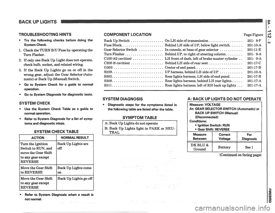
TROlJBLESHQOTlNG HINTS COMPONENT LOCATION Page-Figure
Try the following checks before doing the Back Up Switch ................. On LN side of transmission. ................. 201- 8-F
System Check. Fuse Block. ..................... Behind LH side of IIP, below light switch. ...... 201-10-A
............. ............ 1. Check the TURN BIU Fuse by operating the Gear
Selector Switch In
console, at base of gear selector
201-11-E
.................... Flasher. Flasher Behind IIP, to right of steering column. ........ 201- 9-A
2. If only one Back Up Light does not operate,
check bulb, socket,
and related
3. If the Back Up Lights go on or off in the
mong gear, adjust the Gear Selector (Auto-
matic) or Back Up (Manual) Switch.
el00 (42 cavities) ................ LR front of dash, left of brake master cylinder ..
C208 (8 cavities) ................. Behind LH side of rear seat. .................
6303 .......................... Center of end panel. ........................
S229. .......................... IIP harness, behind LH side of IIP ............
S302. .......................... Rear lights harness, LH side of end panel. ......
S308. .......................... Rear lights harness, behind LH rear lights. ..... - - Go to System Check for a guide to normal S3 11. .......................... Rear lights harness, left of RN back up lights
201-17-A ...
operation.
Go to System Diagnosis for diagnostic tests.
SYSTEM DlAGRlOSlS A: BACK UP LlGHTS DO NOT OPERATE
SYSTEM CHECK
Diagnostic steps for the symptoms listed in
Use the System Check Table as a guide to
the following table are listed
aMer the table. WlTCH (Automatic) or
normal operation. BACK
UP SWITCH
(Manual)
Refer to System Diagnosis for
a list of symp-
toms and diagnostic steps.
SYSTEM CHECK TABLE
the Ignition
Switch to RUN, and
move the Gear Shift
to
any gear except
REVERSE
Move the Gear Shift Back Up Lights come
to REVERSE 1 on - -
Move the Gear Shift Back
Up Lights go off
to any gear except
REVERSE
Refer to System Diagnosis when a result is
SYMPTOM TABLE
A: Back Up Lights do not operate
B: Back Up Lights light in PARK or NEU-
TRAL
(Continued on facing page)
not normal. Between
I Voltage I Diagnosis
I DKBLU& I Battery I See l I Ground
Page 1490 of 1825
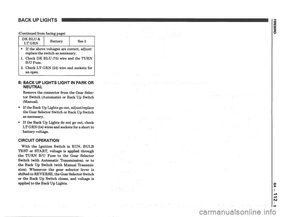
BACK UP LIGHTS
1. Check DK BLU (75) wire and the TURN
B: BACK UP LlGHTS LIGHT IN PARK OR
NEUTRAL
Remove the connector from the Gear Selec-
tor Switch (Automatic) or Back Up Switch
(Manual).
If the Back Up Lights go out, adjustlreplace
the Gear Selector Switch or Back Up Switch
as necessary.
If the Back Up Lights do not go out, check
LT GRN
(24) wires and sockets for a short to
battery voltage.
CIRCUIT OPERATION
With the Ignition Switch in RUN, BULB
TEST or START, voltage is applied through
the TURN
BIU Fuse to the Gear Selector
Switch (with Automatic Transmission), or to
the Back Up Switch (with Manual Transmis-
sion). Whenever the gear selector lever is
s&&ed to REVERSE, the Gear Selector Switch
or the Back Up Switch closes, and voltage is
applied to the Back Up Lights.
Page 1530 of 1825
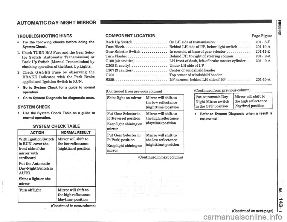
AUTOMATIC DAY-NIGHT MIRROR
TROUBLESHOOTING MINTS
Try the following checks before doing the
System
Gheck.
1. Check TURN BIU Fuse and the Gear Selec-
tor Switch (Automatic Transmission) or
Back
Up Switch (Manual 'L'ransfission) by
checking operation of the Back Up Lights.
2. Check GAGES Fuse by observing the
BRAKE Indicator with the Park Brake
applied and
IMtion Switch in RUN.
@ Go to System Gheck for a guide to normal
operation.
Go to System Diagnosis for diagnostic tests.
Use the System Check Table as a guide to
normal operation.
SYSTEM CHECK TABLE
nighttime) position
t the Automatic
ay-Night Switch
in
Shine a light on the
COMPONENT LOCATION Page-Figure
.................. Back Up Switch ................. On LN side of transIlnission 201- 8-F
...... Fuse Block. ..................... Behind LN side of IIP, below light switch. 201-10-A
............ Gear
Selector Switch ............. In console, at base of gear selector 201-11-E
........ 'Turn Flasher .................... Behind
PIP, to right of steering column. 201-
9-A
.. C100 (42 cavities) ................ LR front of dash, left of brake master cylinder 201-
0-A
6305 (1 cavity) .................. Under LH side of IIP
C307 (3 cavities) ................. Center of windshield header
6201
.......................... Top center of windshield header
............ S229. .......................... IIP harness, behind LW side of IIP 201-10-A
(Continued from previous column)
(Continued in next co (Continued
from previous column)
Refer to System Diagnosis when a result is
not normal.
(Continued in next colum)
(Continued on next page)
Page 1569 of 1825
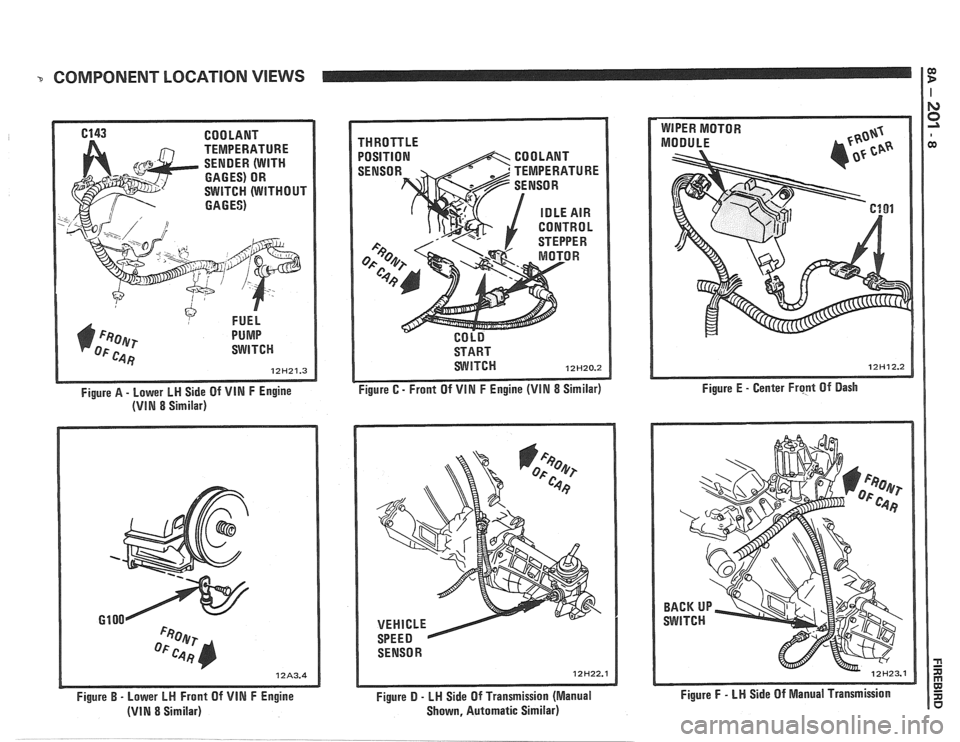
COMPONENT LOCATION VIEWS I $
6143 COOLANT
TEMPERATURE
SENDER (WITH
GAGES) OR
SWITCH (WITHOUT
GAGES)
FUEL
1) F~oer PUMP
OF c.4 Fj SWITCH
12H21.3
Figure A - Lower LH Side Of VIN F Engine
(VIN 8 Similar)
Figure
B - Lower LH Front Of VIN F Engine
(VIN 8 Similar) THROTTLE
POSITION
START
WITCH 12H20.2
Figure C - Front Of VIN F Engine (VIM 8 Similar)
SENSOR
12H22.1
Figure D - LH Side Of Transmission (Manual
Shown, Automatic Similar) Figure
E
- Center Frcpt Of Dash
Figure
F - LN Side Of Manual Transmission