1988 PONTIAC FIERO transmission
[x] Cancel search: transmissionPage 1594 of 1825
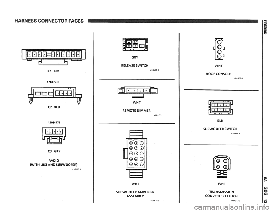
HARNESS CONNECTOR FACES
C1 BLK
12047530
C2 BLU
CRY
RELEASE SWITCH
WHT
REMOTE DIMMER
V00412 1
C3 GRY
RADIO
(WITH UK3 AND SUBWOOFER)
V00579 0
SUBWOOFER AMPLIFIER
ASSEMBLY
V00576.0
WHT
ROOF CONSOLE
V00515.0
BLK
SUBWOOFER SWITCH
V00577.0
WHT
TRANSMISSION
CONVERTER CLUTCH
V040 17.2
Page 1600 of 1825
LIGHTING SYSTEMS AND HORNS 8B-I
SECTION 8B
NG SYSTEMS AND HORNS
CONTENTS
........................... GENERAL DESCRIPTION 8B-1
Exterior Lights
....................... ................... Back-up Lights .. 8B- 1
Center High-Mounted Stoplight .................... 8B-1
Exterior Light Monitor .................................. 8B-1
............................ .................... Fog Lights .. 8B-1
Front Parking/Turn Signal Lights ................ 8B-2
............................... Hazard Flashers .. ........ 8B-2 .................................................... Headlights 8B-2
License Plate Lights ..................................... 8B-2
Light Switch ............................................... 8B-2
............... Rear Tail/Stop/Turn Signal Lights 8B-2
Sidemarker Lights ........................................ 8B-2
Turn Signals .......................................... 8B-2
......................... Underhood Light ... ........ 8B-2
Horns .......................................................... 8B-3
....................................... ON-CAR SERVICE 8B-3
Exterior Lights
............................................. Back-up Lights 8B-3
Center High-Mounted Stoplight .................... 8B-3
Fog Lights .................................................... 8B-4
Front Parking/Turn Signal Lights ................ 8B-4
Hazard Flasher .............................................. 8B-5
....................................................... Headlights 8B-5
License Plate Lights ..................................... 8B-7
............... Rear Tail/Stop/Turn Signal Lights 8B-8
.......................................... Sidemarker Lights 8B-8
................... ............... Turn Signal Flasher .. 8B-9
......................................... Underhood Light 8B-9
Horns ................................................................. 8B-9
REPLACEMENT BULB
.................................... SPECIFICATIONS 8B- 10
The following information, previously shown in this section,
has been moved to the sections shown.
Back-up Lights Switch
............................. ... ............................................................................ 7
................................................................................................................................. Fuse Block 8A
Ignition Switch ........................................................................................................................... 3B
Interior Lights
................................................................................................................... 8A, 8C
Neutral Start Switch ..................................................................................................................... 7
Parking Brake Warning Switch
......................... ... .................................................................... 5
........................................................................ Seat Belt, Key and Headlight Warning Alarm 8A
Stoplight Switch .......................... .. ............................................................................................... 5
Windshield
Wipers/Washers .................................................................................................... 8E
GENERAL DESCRIPTION
The exterior lighting system includes the
headlights (and headlight motors to raise or lower the
headlights), front
parkinghurn signal lights, front
cornering lights, fog lights, rear
tail/stop/turn signal
lights, back-up lights, license plate lights, center
high-mounted stoplight, and the underhood light; it
also includes all associated wiring, controls and related
hardware for these lights.
BACK-UP LIGHTS - The back-up lights are
next to the rear license plate. They will come on when
the transmission is shifted to Reverse. On cars with an
automatic transmission, the back-up lights are
activated by the neutral start switch. On cars with a
manual transmission, they are activated by a separate
back-up light switch on the transmission. For more
information, see Section 7.
CENTER HIGH-MOUNTED STOPLIGHT-
The center high-mounted stoplight, in the center of the
rear spoiler, will come on whenever the brake pedal is
pushed down. The light is powered separately from the rear
tail/stop/turn signal
lights through a separate
circuit in the stoplight switch (see Section
8A).
EXTERIOR LIGHT MONITOR - The Driver
Information Center, on cars so equipped, also monitors
certain front and rear lights. When a bulb burns out,
the message
"FRONT LAMP" or "REAR LAMP"
will appear in the DIC display, and a light will come
on to indicate which bulb has burned out. For more
information, see Section
8A.
FOG LIGHTS -The fog light switches are to the
left of the steering column on the edge of the
instrument panel. To use the fog lights, first turn on the
headlights or parking lights. Then, push the middle
switch (with the fog light symbol) to turn on the fog
lights. Push the left
("OFF") switch to turn off the fog
lights.
The fog lights should not be used as a substitute
for the headlights.
Switching to high-beam headlights will turn off
the fog lights; switching back to low-beams will turn
the fog lights on again.
Page 1602 of 1825
LIGHTING SYSTEMS AND HORNS 8B-3
HORNS the steering wheel sounds the horn by closing the horn
relay (in the convenience center behind the instrument
panel, to the right of the steering column). The horns
The holm(§) are mounted behind the front fascia use a solenoid-operated diaphragm to generate sound.
on the driver's side. $ushing the pad in the center of See Section 8A-40 for wiring and circuit information.
ON-CAR SERVICE
Wiring diagrams and other diagnosis information
is given in Section
8A. Information on properly
repairing wiring harnesses, connectors, etc., is on
8A-5.
Most lighting problems are caused by loose
connectors, open or shorted wiring, burned-out bulbs,
bad switches, inadequate ground or blown fuses. Many
of these require only replacement of a defective part.
When replacing a part that requires a special procedure
(such as a lens and housing assembly sealed together),
follow the instructions normally included in the
replacement parts package.
When removing a part that requires special
sealing items (such as sealing washers), be sure to
reinstall those items when replacing the part. Also, if
any body sealing items (grommets, etc.) are disturbed,
be sure to repair them so the passenger compartment
remains properly sealed.
EXTERlOR LIGHTS
BACK-UP LIGHTS
Fig. 8B-8
Replacement Bulb: Trade No. 1156, 32
Candlepower
To replace a back-up light bulb, see "Rear
Tail/Stop/Turn Signal Lights9' in this section. For
information on the back-up light switch on the
transmission, see Section
7.
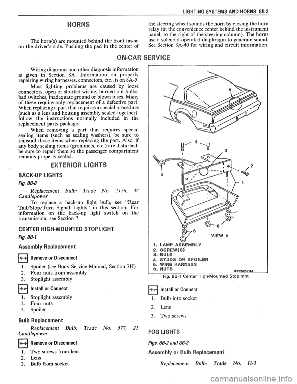
CENTER HIGH-MOUNTED STOPLIGHT
Fig. 8B-7
Assembly Replacement
Remove or Disconnect
1. Spoiler (see Body Service Manual, Section 7H)
2. Four nuts from assembly
3. Stoplight assembly
Install or Connect
1. Stoplight assembly
2. Four nuts
3. Spoiler
Bulb Replacement
Replacement Bulb: Trade No. 577, 21
Candlepo wer
Remove or Disconnect
1. Two screws from lens
2. Lens
3. Bulb from socket
1. LAMP ASSEMBLY
2. SCREW($) 3. BULB
4. STUD8 ON SPOILER 5. WIRE HARNESS
Fig. 8B-1 Center High-Mounted Stoplight
Install or Corrnect
1. Bulb into socket
2. Lens
3. Two screws
FOG LIGHTS
Figs. 8B-2 and 88-3
Assembly or Bulb Replacement
Replacement Bulb: Trade No. H-3
Page 1613 of 1825

842-2 INSTRUMENT PANEL. GAGES & CONSOLE
Pinion Gear
The PINION GEAR is attached to the
traaasmission/transaxle output shaft and rotates in
proportion to the speed of the car. This rotation is
transferred from the pinion gear to the speedometer
head by the speedometer cable.
Photo Speed Sensor
On vehicles that use a mechanical drag-cup
speedometer, the PHOTO SPEED SENSOR is
inserted into the frame of the mechanical speedometer
to provide an electrical feedback to the ECM that
represents vehicle speed. The ECM needs to know how
fast the car is traveling in order to control and operate
the cruise control, cooling fan, and transmission and
evaporative systems.
The photo speed sensor is made up of two special
electronic devices: a Eight-Emitting Diode (LED) and
a photo transistor (a light-sensitive amplifying device).
In the mechanical speedometer, there is a reflective
blade attached to the rotating magnet that is polished
to
reflect light from the LED back to the photo
transistor. Whenever the light strikes the photo
transistor, it conducts electricity. The rate that the
transistor conducts and does not conduct is
proportional to the speed of the magnet, which reflects
the speed of the vehicle. This voltage signal from the
photo transistor is sent to a buffer amplifier (part of the
speed sensor) to be conditioned to a signal the ECM
can understand and use.
PM Generator
The PM (Permanent Magnet) GENERATOR is
a small
AC generator used to sense vehicle speed. The
shaft of the generator fits into a pinion gear in the
transmission/transaxle output shaft (as does the cable
in
a mechanical system).
When the output shaft rotates, the magnet rotates
and generates a voltage. Except for the permanent
magnet, the
PM Generator is exactly like a miniature
alternator. The PM generator is constructed to provide
a voltage whose frequency is about
1.1 cycles per
second for every mile per hour of vehicle speed. This
signal is sent to a buffer amplifier, and then to the
speedometer and the
EGM.
SPEEDOMETER
The speedometer is a road speed indicator with
an odometer to record total mileage, and, on some cars,
a resettable trip odometer.
The major types of speedometers in use are
mechanical instruments and electronic instruments.
Mechanical speedometers use a dial needle to indicate
road speed. Electronic speedometers include
instruments that use a dial indicator and those using
bar-graph
LCD's (Liquid Crystal Displays) or VTF
(Vacuum Tube Fluorescent) displays.
Meehanice! Speedometers
A mechanical speedometer uses a cable driven
(through a pinion gear) by the transmission output
shaft. The cable connects to a magnetic drag-cup inside the
speedometer, which rotates the speedometer
needle. The end of the rotating cable causes a small bar
magnet to rotate within a metal cup. As the magnet
rotates within the cup, it magnetically attracts (drags)
the metal cup along behind it. Two things work to
prevent the cup from rotating as quickly as the magnet.
1. The distance of the magnet from the cup reduces
its effect on the cup.
2. A counterspring is wound around the shaft of the
cup in such a way as to oppose the normal
rotation of the cup. The counterspring loads the
drag-cup to give correct indication of the speed,
prevent needle overshoot, and also to return the
drag cup to a zero point.
Mechanical speedometers require a photo speed
sensor to provide road speed information for the ECM
and other systems, such as Cruise Control and the TCC
(Torque Converter Clutch).
The odometer on these instruments consists of
numbered wheels that are rotated by the speedometer
cable through worm gears.
Quartz Speedometer
The quartz speedometer is an electrically driven
instrument. The indicator needle is driven by a
precision DC motor, and is countersprung to provide
a mechanical load, prevent overshoot of the needle, and
return the indicator to zero when the road speed is
zero.
The source of speed information for a quartz
speedometer is the PM generator. From the PM
generator, speed information goes to the buffer
amplifier to be converted to digital voltage, and then
to the cluster circuitry, which interprets the speed of
the vehicle and produces small voltage to apply to the
speedometer motor.
The odometer on this instrument consists of
numbered wheels that are electrically driven by a
special precision DC motor called a stepper motor.
Digital Speedometer
Digital clusters utilize two types of displays: LCD
(Liquid Crystal Display) and VTF (Vacuum Tube
Fluorescent). They are used in digital speedometers
and bar-graph tachometers, fuel gages, etc.
Speed information entering the cluster from the
buffer amplifier is interpreted by a microcomputer
which controls the speed indication, the tachometer
display and the odometer reading.
The odometers associated with these instruments
utilize either numbered wheels driven by a small motor
or electronic displays. With an electronic display, the
mileage reading is stored in a computer chip (called a
non-volatile RAM chip; NVRAM) that does not
become 'erased' when the vehicle is turned off,
as the
display does not retain the information.
FUEL GAGE
An electrical fuel gage is used on all models,
consisting of an instrument panel gage and a fuel tank
pick-up. The fuel gage indicates the quantity of fuel in
Page 1614 of 1825
INSTRUMENT PANEL. GAGES & CONSOLE 8C-3
tank only when ignition switch is turned to "ON" or
"ACCESSORY" positions.
When ignition is turned to "OFF" or "START"
positions, the pointer may come to rest at any position.
The letters
"E" and "F" on the fuel gage are used to
point out direction of indicator travel only.
TEMPERATURE WARNING LIGHT
The engine temperature warning light is
controlled by a thermal switch which senses engine
coolant temperatures.
When the ignition switch is turned to "START"
position, a test circuit is closed and the light will come
on to indicate whether the light is functioning properly.
It is important to note that with low boiling-point
coolants (such as plain water) the temperature light
may not come on even though the coolant is boiling.
GENERATOR WARNING LIGHT
The generator warning light, located in the
instrument cluster, should come on when the ignition
switch is turned
"ON" and engine is not running. If
not, either the bulb is burned out or wiring to generator
has an open circuit.
When the generator voltage output becomes
greater than the battery voltage, the
"GEN" light
should go out. This does not, however, indicate
whether the battery is being charged or if the voltage
regulator is functioning properly.
Checks of the charging system are covered in
Section 6D, 'Engine Electrical'.
ENGINE OIL PRESSURE LIGHT
The engine oil pressure warning light is mounted
in the instrument cluster and controlled by a pressure
operated switch located on the engine block. When the ignition switch is
in the
"run" or "start9' position, the
oil pressure light should come on. If not, the bulb is
burned out, there is an open circuit between the bulb
and the oil pressure switch, or there is an open circuit
between the oil pressure switch and the choke heater.
After the engine is running, the oil pressure light
should go out when the oil pressure reaches the correct
specification. If not an oil pressure problem, a faulty oil
pressure switch or an open circuit from the choke
heater fuse to the oil pressure switch is indicated.
"SERVICE ENGINE SOON" LIGHT
All cars have a "SERVICE ENGINE SOON"
light mounted in the instrument cluster. The
"SERVICE ENGINE SOON9' light should come on
during engine starting. The light may stay on
a short
time after the engine starts.
If the light comes on while
driving, service to the emission control system may be
required. See Section
6E and Section 8A-80,
'Instrument Cluster', for complete diagnosis and
wiring diagrams of the
""P;RVICE ENGINE SOON"
light circuit.
UPSHIFT INDICATOR LIGHT
If your vehicle has a manual transmission, there
may be an
''Upshift" light on the instrument panel.
This light is illuminated to indicate optimum shift
points throughout the range from optimum fuel
economy to optimum performance. When this light is
on, shift your transmission to the next higher gear
range if conditions permit. For fuel economy,
accelerate slowly and shift when the light goes on. For
performance, accelerate as desired and shift when the
light goes on.
Safe operation of the vehicle may require shifting
differently than indicated by the "Upshift" light to
adapt to weather, road or traffic conditions.
Downshifting one or more gears may be required
to keep the engine running smoothly or to maintain
satisfactory performance.
DIAGNOSIS
Diagnostic information for all instrument panel
electrical systems is found in Section
8A-80,
'Instrument Panel'.
CAUTION: When removing or
installing any electrical units,
disconnect the negative battery cable
to prevent possible short circuits
which could lead to personal injury
and/or property damage. When
replacing a speedometer or
odometer assembly, the law requires the
odometer reading of the replacement unit to
be set to register the same mileage as the
prior odometer.
if the same mileage cannot be
set, the
law requires that the replacement
odometer be set to zero and a label be
installed on the driver's door frame to show
the previous odometer reading and the date
of replacement.
GENERAL BNFORMATlOM
INSTRUMENT PANEL AND GAGES
The instrument panel is a single unit design and
and screws. To service the instrument panel and
all parts attach to the main instrument panel with clips components see Figs. 601 through 610.
Page 1628 of 1825
WINDSI4IELD WIPER SYSTEMS - F CARLINE 8E -1
SECTION 8E
F CARL
ELD W PER-WASHER SYSTEM
PULSE & STANDARD
CONTENTS
General Description ....................... 8E -1 Park Switch Replacement ............... .8E -3
Wiper and Washer Operation
............ 8E -1
Wiper Motor Replacement .............. 8E -1 1
Pulse Windshield Wiper System
........... 8E -1
Wiper Transmission .................... 8E -1 1
Diagnosis Wiper Arm
........................... 8E -12
Diagnostic Procedures
................... 8E -2 Wiper Blade ........................... 8E -13
Wiper Motor
........................... 8E -2 Wiper Blade Insert ..................... 8E -14
Washer Pump
.......................... 8E -2 Windshield Washer ..................... 8E -15
........................ Diagnostic Chart 8E -3 Unit Repair
On-Car Service Gear Replacement
..................... 8E - 15
Washer Pump Replacement .............. 8E -3 Wiper-Washer Nozzle and Container
Wiper Cover Replacement
............... 8E -3 Mounting ........................... 8E -1 8
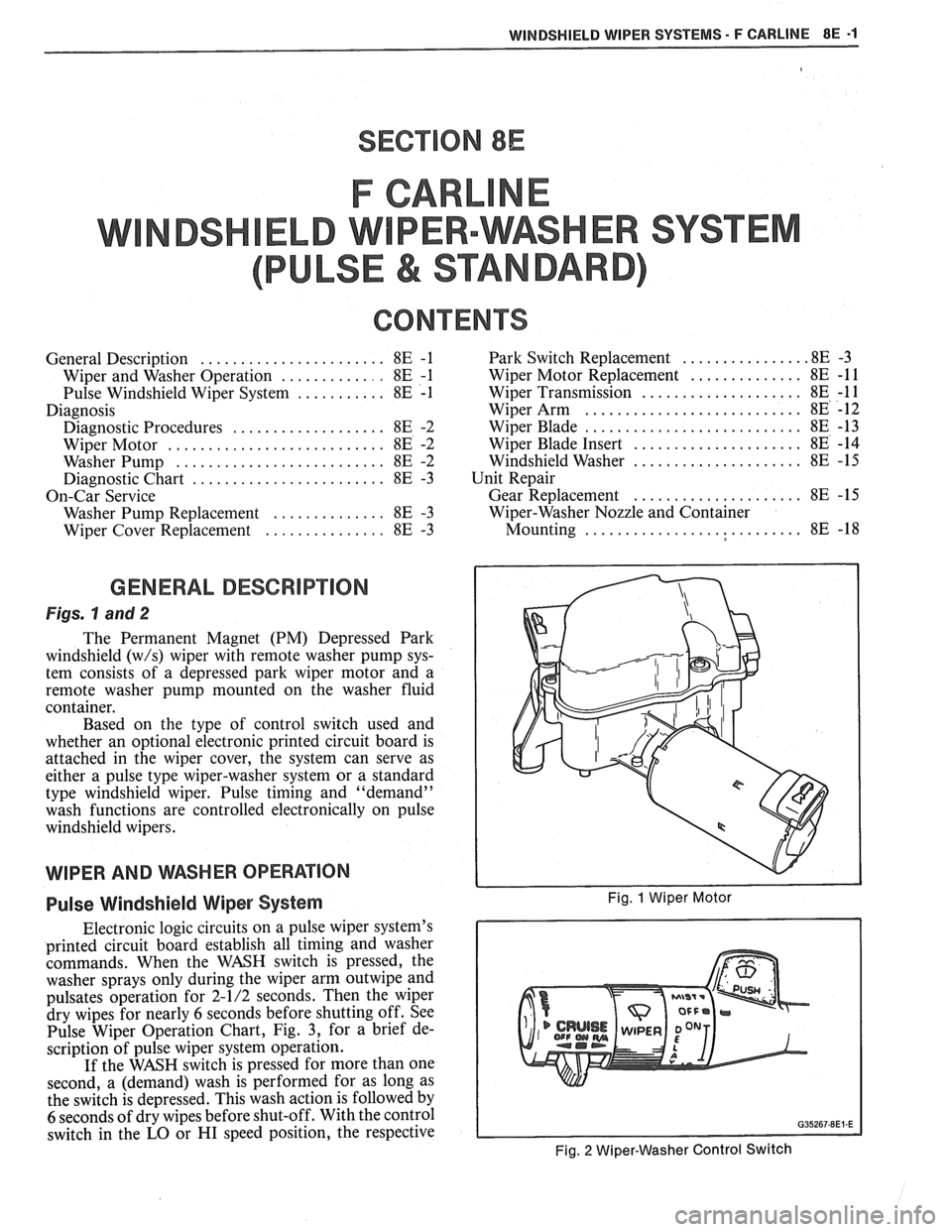
GENERAL DESCRIPTION
Figs. hand 2
The Permanent Magnet (PM) Depressed Park
windshield
(w/s) wiper with remote washer pump sys-
tem consists of a depressed park wiper motor and a
remote washer pump mounted on the washer fluid
container.
Based on the type of control switch used and
whether an optional electronic printed circuit board is
attached in the wiper cover, the system can serve as
either a pulse type wiper-washer system or a standard
type windshield wiper. Pulse timing and "demand"
wash functions are controlled electronically on pulse
windshield wipers.
WIPER AND WSHER OPERAflON
Pulse Windshield Wiper System Fig. 1 Wiper Motor
Electronic logic circuits on a pulse wiper system's
printed circuit board establish all timing and washer
commands. When the WASH switch is pressed, the
washer sprays only during the wiper arm
outwipe and
pulsates operation for 2-1/2 seconds. Then the wiper
dry wipes for nearly
6 seconds before shutting off. See
Pulse Wiper Operation Chart, Fig.
3, for a brief de-
scription of pulse wiper system operation.
If the WASH switch is pressed for more than one
second, a (demand) wash is performed for as long as
the switch is depressed. This wash action is followed by
6 seconds of dry wipes before shut-off. With the control
switch in the
LO or HI speed position, the respective
Fig. 2 Wiper-Washer Control Switch
Page 1638 of 1825
WINDSHIELD WIPER SYSTEMS - F CARLINE BE -11
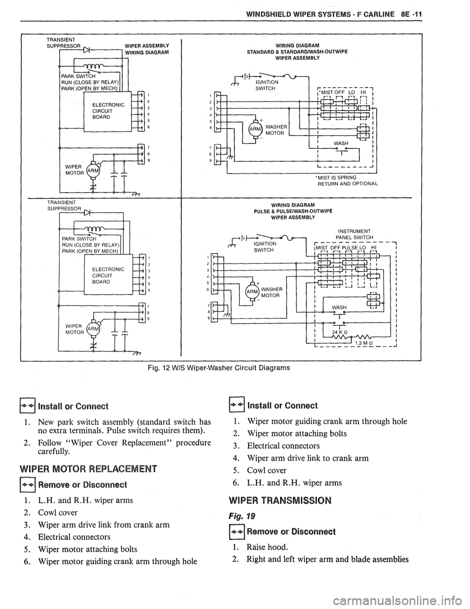
IPER ASSEMBLY WIRING DIAGRAM IRING DIAGRAM STANDARD & STANDARDIWASH.OUTWIPE WIPER ASSEMBLY
ELECTRONIC
Fig. 12 WIS Wiper-Washer Circuit Diagrams
Install or Connect
1. New park switch assembly (standard switch has
no extra terminals. Pulse switch requires them).
2. FoIlow "Wiper Cover Replacement" procedure
carefully.
WIPER MOTOR REPLACEMENT
Remove or Disconnect
1. L.H. andR.H. wiper arms
2. Cowl cover
3. Wiper arm drive link from crank arm
4. Electrical connectors
5. Wiper motor attaching bolts
6. Wiper motor guiding crank arm through hole
Install or Connect
1. Wiper motor guiding crank arm through hole
2. Wiper motor attaching bolts
3. Electrical connectors
4. Wiper arm drive link to crank arm
5. Cowl cover
6. L.H. and R.H. wiper arms
WIPER TRANSMISSION
Fig. 19
Remove or Disconnect
1. Raise hood.
2. Right and left wiper arm and blade assemblies
Page 1639 of 1825
8E -12 WINDSHIELD WIPER SYSTEMS. F CAWLINE
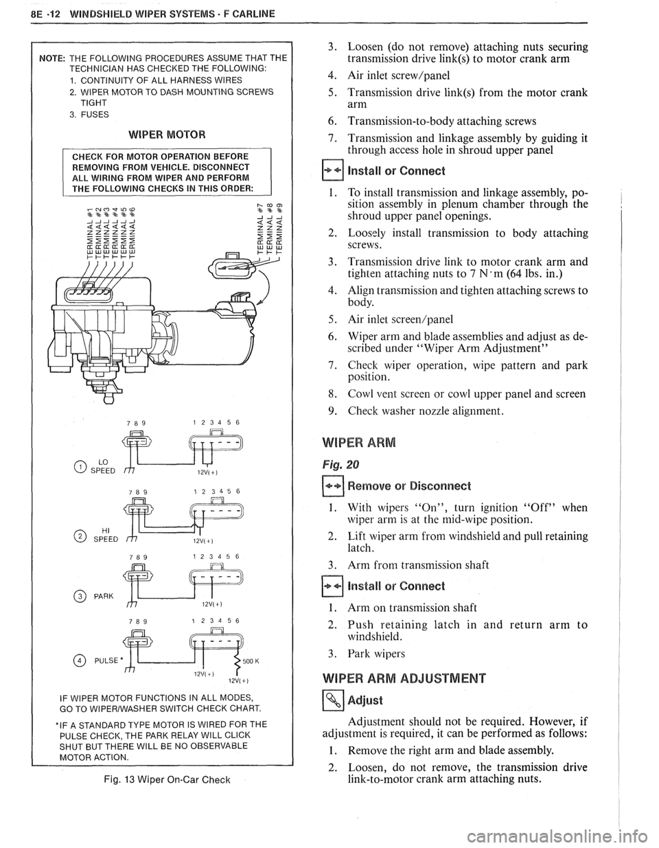
2. WIPER MOTOR TO DASH MOUNTING SCREWS
WIPER MOTOR
REMOVING FROM VEHICLE. DISCONNECT
ALL WIRING FROM WIPER AND PERFORM
GO TO WlPERlWASHER SWITCH CHECK CHART.
E PARK RELAY
WlLL CLICK WlLL BE NO OBSERVABLE
Fig. 13 Wiper On-Gar Check
3. Loosen (do not remove) attaching nuts securing
transmission drive
link(s) to motor crank arm
4. Air inlet screw/panel
5. Transmission drive link(s) from the motor crank
arm
6. Transmission-to-body attaching screws
7. Transmission and linkage assembly by guiding it
through access hole in shroud upper panel
install or Connect
1. To install transmission and linkage assembly, po-
sition assembly in plenum chamber through the
shroud upper panel openings.
2. Loosely install transmission to body attaching
screws.
3. Transmission drive link to motor crank arm and
tighten attaching nuts to
7 N'm (64 lbs. in.)
4. Align transmission and tighten attaching screws to
body.
5. Air inlet screen/panel
6. Wiper arm and blade assemblies and adjust as de-
scribed under "Wiper Arm Adjustment"
7. Check wiper operation, wipe pattern and park
position.
8. Cowl vent screen or cowl upper panel and screen
9. Check washer nozzle alignment.
WIPER ARM
Fig. 20
Remove or Disconnect
1. With wipers "On", turn ignition "Off" when
wiper arm is at the mid-wipe position.
2. Lift wiper arm from windshield and pull retaining
latch.
3. Arm from transmission shaft
Install or Connect
1. Arm on transmission shaft
2. Push retaining latch in and return arm to
windshield.
3. Park wipers
WIPER ARM ADJUSTMENT
Adjust
Adjustment should not be required. However, if
adjustment is required, it can be performed as follows:
1. Remove the right arm and blade assembly.
2. Loosen, do not remove, the transmission drive
link-to-motor crank arm attaching nuts.