1988 PONTIAC FIERO transmission
[x] Cancel search: transmissionPage 1142 of 1825
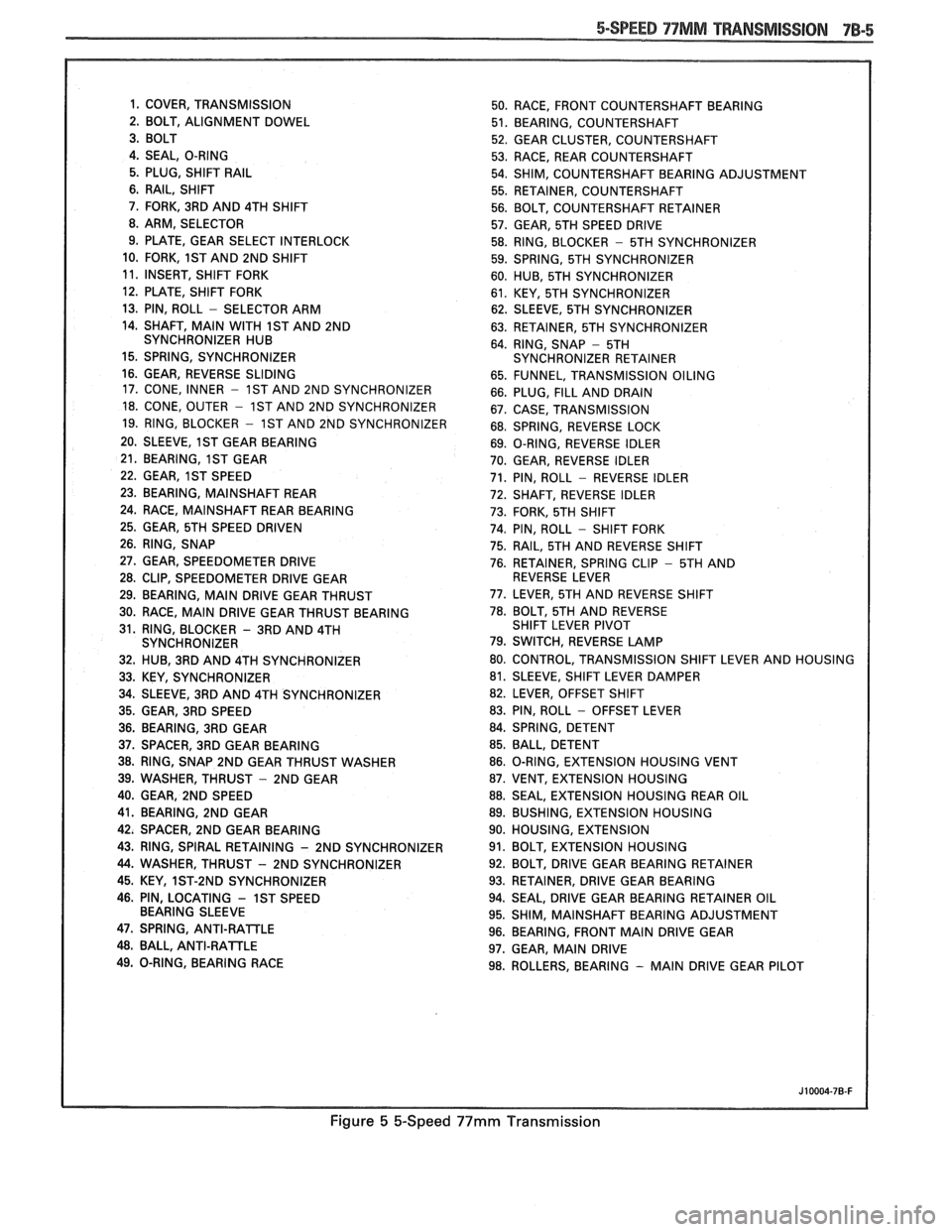
5-SPEED 97MM TRANSMISSION 7B-5
1. COVER, TRANSMISSION
50. RACE, FRONT COUNTERSHAFT BEARING
2. BOLT, ALIGNMENT DOWEL
51. BEARING, COUNTERSHAFT
52. GEAR CLUSTER, COUNTERSHAFT
4. SEAL, O-RING
53. RACE, REAR COUNTERSHAFT
5. PLUG, SHIFT
RAIL 54. SHIM, COUNTERSHAFT BEARING ADJUSTMENT
6. RAIL, SHIFT
55. RETAINER, COUNTERSHAFT
7. FORK, 3RD AND 4TH SHIFT
56. BOLT, COUNTERSHAFT RETAINER
8. ARM, SELECTOR
57. GEAR, 5TH SPEED DRIVE
9. PLATE, GEAR SELECT INTERLOCK
58. RING, BLOCKER
- 5TH SYNCHRONIZER
10. FORK,
1ST AND 2ND SHIFT
59. SPRING, 5TH SYNCHRONIZER
11. INSERT, SHIFT FORK
60. HUB, 5TH SYNCHRONIZER
12. PLATE, SHIFT FORK
61. KEY, 5TH SYNCHRONIZER
13. PIN, ROLL
- SELECTOR ARM
62. SLEEVE, 5TH SYNCHRONIZER
14. SHAFT,
MAIN WITH 1ST AND 2ND
63. RETAINER, 5TH SYNCHRONIZER
SYNCHRONIZER HUB
64. RING, SNAP
- 5TH
15. SPRING, SYNCHRONIZER SYNCHRONIZER RETAINER
16. GEAR, REVERSE SLIDING
65. FUNNEL, TRANSMISSION OILING
17. CONE, INNER
- 1ST AND 2ND SYNCHRONIZER
66. PLUG, FILL AND DRAIN
18. CONE, OUTER - 1ST AND 2ND SYNCHRONIZER
67. CASE, TRANSMISSION
19. RING, BLOCKER
- 1ST AND 2ND SYNCHRONIZER
68. SPRING, REVERSE LOCK
20. SLEEVE,
1ST GEAR BEARING
69. O-RING, REVERSE IDLER
21. BEARING,
1ST GEAR
70. GEAR, REVERSE IDLER
22. GEAR,
1ST SPEED 71. PIN, ROLL - REVERSE IDLER
23. BEARING, MAINSHAFT REAR
72. SHAFT, REVERSE IDLER
24. RACE,
MAINSHAFT REAR BEARING
73. FORK, 5TH SHIFT
25. GEAR, 5TH SPEED DRIVEN
74. PIN, ROLL - SHIFT FORK
26. RING, SNAP
75. RAIL, 5TH AND REVERSE SHIFT
27. GEAR, SPEEDOMETER DRIVE
76. RETAINER, SPRING CLIP - 5TH AND
28. CLIP, SPEEDOMETER DRIVE GEAR REVERSE LEVER
29. BEARING,
MAIN DRIVE GEAR THRUST 77.
LEVER, 5TH AND REVERSE SHIFT
30. RACE,
MAIN DRIVE GEAR THRUST BEARING 78. BOLT, 5TH
AND REVERSE
31. RING, BLOCKER
- 3RD AND 4TH SHIFT
LEVER PIVOT
SYNCHRONIZER 79. SWITCH, REVERSE LAMP
32. HUB, 3RD AND 4TH SYNCHRONIZER 80.
CONTROL, TRANSMISSION SHIFT LEVER AND HOUSING
33. KEY, SYNCHRONIZER 81.
SLEEVE, SHIFT LEVER DAMPER
34. SLEEVE, 3RD AND 4TH SYNCHRONIZER 82.
LEVER, OFFSET SHIFT
35. GEAR, 3RD SPEED 83. PIN, ROLL
- OFFSET
LEVER
36. BEARING, 3RD GEAR 84.
SPRING, DETENT
37. SPACER, 3RD GEAR BEARING 85.
BALL, DETENT
38. RING, SNAP 2ND GEAR THRUST WASHER 86.
O-RING, EXTENSION HOUSING VENT
39. WASHER, THRUST
- 2ND GEAR 87. VENT, EXTENSION HOUSING
40. GEAR, 2ND SPEED 88. SEAL, EXTENSION HOUSING REAR OIL
41. BEARING, 2ND GEAR 89. BUSHING, EXTENSION HOUSING
42. SPACER,
2ND GEAR BEARING 90.
HOUSING, EXTENSION
43. RING, SPIRAL RETAINING
- 2ND SYNCHRONIZER 91. BOLT, EXTENSION HOUSING
44. WASHER, THRUST - 2ND SYNCHRONIZER 92.
BOLT, DRIVE GEAR BEARING RETAINER
45. KEY, 1ST-2ND SYNCHRONIZER 93.
RETAINER, DRIVE GEAR BEARING
46. PIN, LOCATING
- 1ST SPEED 94. SEAL, DRIVE GEAR BEARING RETAINER OIL
BEARING SLEEVE
95. SHIM,
MAINSHAFT BEARING ADJUSTMENT
47. SPRING, ANTI-RAlTLE 96. BEARING, FRONT MAIN DRIVE GEAR 48. BALL, ANTI-RATTLE
97. GEAR, MAIN DRIVE
49. O-RING, BEARING RACE
98. ROLLERS, BEARING
- MAIN DRIVE GEAR PILOT
Figure 5 &Speed 99mm Transmission
Page 1143 of 1825
Install or Conned
1. New seal using Tool J 21426.
2. Propeller shaft. (See Section 4A)
3. Lower vehicle.
4. Check transmission fluid level.
SPEEDOMETER DRIVEN GEAR
Remove or Disconnect
1. Raise vehicle.
2. Speedometer cable.
3. Lock plate and retaining bolt.
4. Pry gear fitting and shaft from housing.
5. O-ring from fitting.
Install or Connecl
1. Coat driven gear shaft and new O-ring with
transmission lubricant.
2. New O-ring.
3. Insert shaft.
4. Position fitting into extension housing.
5. Lock plate and retaining bolt.
6. Speedometer cable.
7. Lower vehicle.
TRANSMISSION
Figure 4
Disassemble
@ Exterior of the transmission assembly
thoroughly with appropriate solvent.
1. Remove drain bolt on transmission case and
drain lubricant.
2. Position offset lever in neutral gate (centered).
NO"6CE: Removal of offset lever in position
other than neutral (centered) may result in driving
the roll pin into the detent plate without releasing
lever, making further disassembly extremely
difficult.
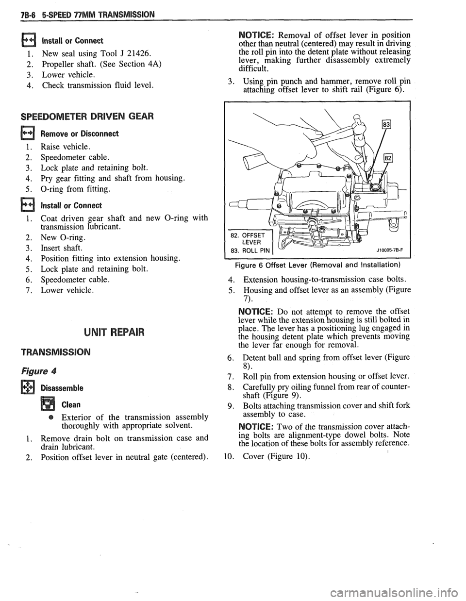
3. Using pin punch and hammer, remove roll pin
attaching offset lever to shift rail (Figure
6).
Figure 6 Offset Lever (Removal and Installation)
4. Extension housing-to-transmission case bolts.
5. Housing and offset lever as an assembly (Figure
7) *
NOTICE: Do not attempt to remove the offset
lever while the extension housing is still bolted in
place. The lever has a positioning lug engaged in
the housing detent plate which prevents moving
the lever far enough for removal.
6. Detent ball and spring from offset lever (Figure
8)
7. Roll pin from extension housing or offset lever.
8. Carefully pry oiling funnel from rear of counter-
shaft (Figure
9).
9. Bolts attaching transmission cover and shift fork
assembly to case.
NOTICE: Two of the transmission cover attach-
ing bolts are alignment-type dowel bolts. Note
the location of these bolts for assembly reference.
10. Cover (Figure 10). I
Page 1144 of 1825
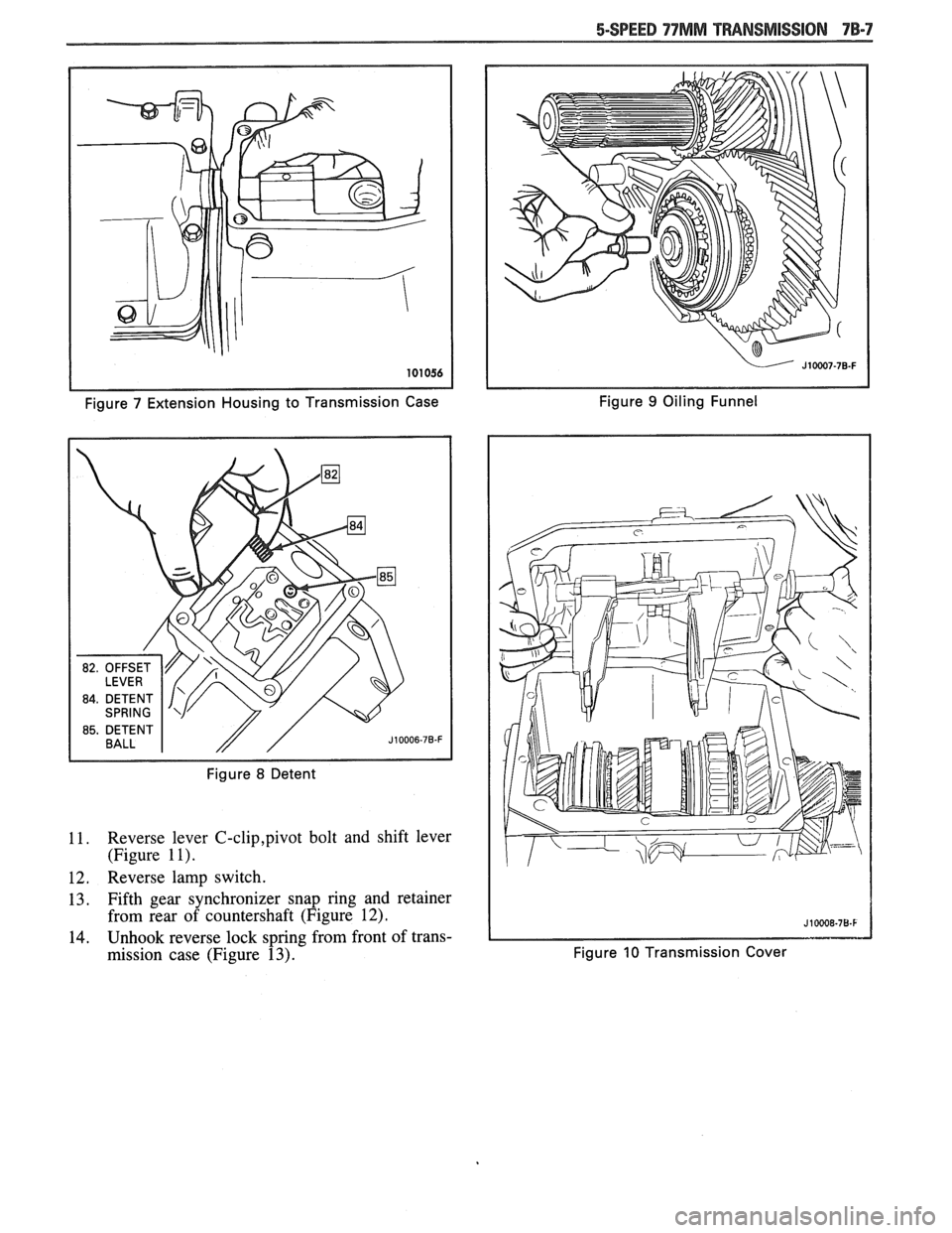
Figure 7 Extension Housing to Transmission Case Figure 9 Oiling
Funnel
Figure
8 Detent
11. Reverse lever C-clip,pivot bolt and shift lever
(Figure
1 I).
12. Reverse lamp switch.
13. Fifth gear synchronizer snap ring and retainer
from rear of countershaft (Figure
12).
14. Unhook reverse lock spring from front of trans-
mission case (Figure
13). Figure 10 Transmission Cover
Page 1146 of 1825
BEARING RETAINER
Figure 16 Bearing Retainer and Shims Figure 18 Mainshaft
(Removal and Installation)
Figure
17 Drive Gear (Removal and Installation)
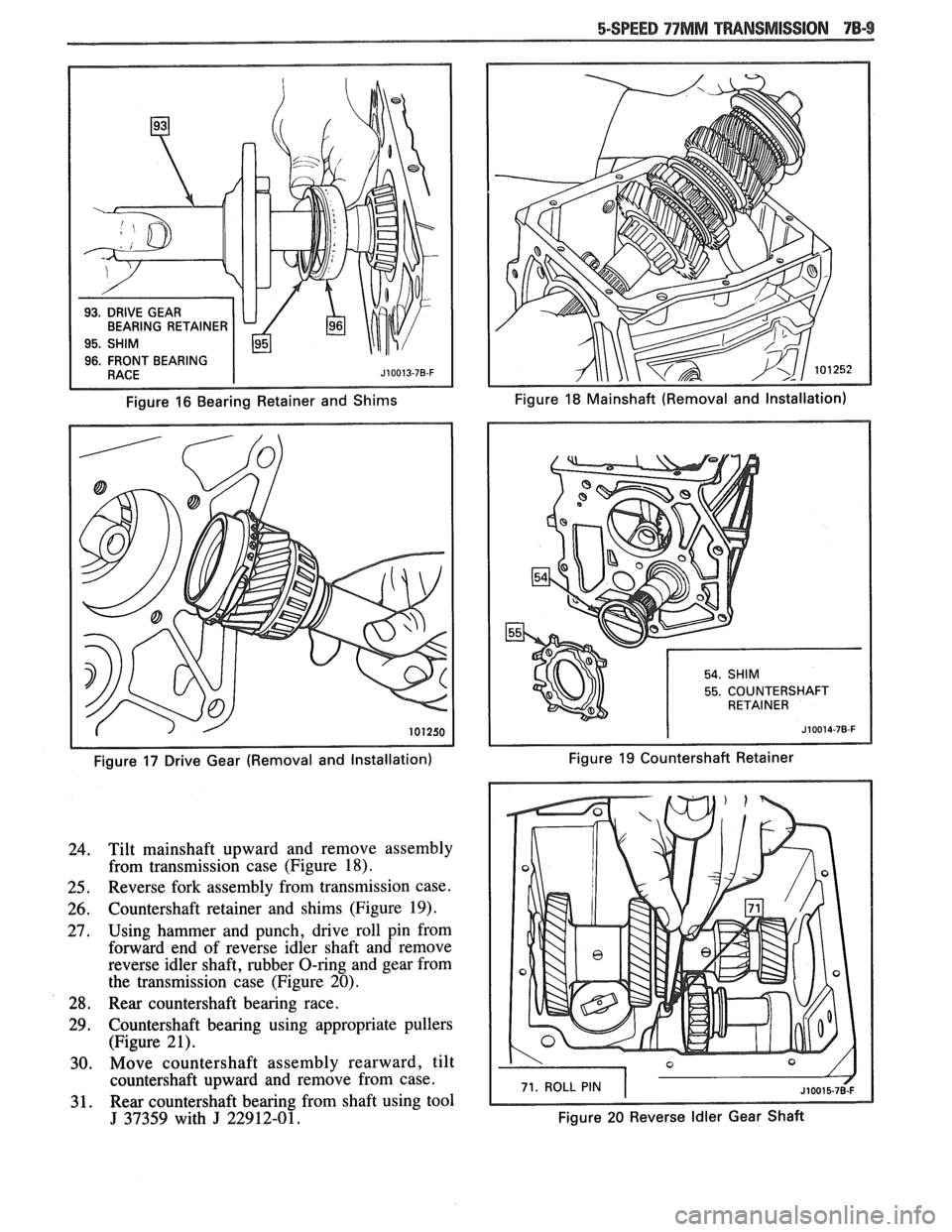
Tilt mainshaft upward and remove assembly
from transmission case (Figure 18).
Reverse fork assembly from transmission case.
Countershaft retainer and shims (Figure 19).
Using hammer and punch, drive roll pin from
forward end of reverse idler shaft and remove
reverse idler shaft, rubber O-ring and gear from
the transmission case (Figure 20).
Rear countershaft bearing race.
Countershaft bearing using appropriate pullers (Figure 21).
Move countershaft assembly rearward, tilt
countershaft upward and remove from case.
Rear countershaft bearing from shaft using tool
J 37359 with J 22912-01.
55. COUNTERSHAFT
Figure 19 Countershaft Retainer
71. ROLL PIN
Figure 20 Reverse Idler Gear Shaft
Page 1148 of 1825
5-SPEED 77MM TRANSMISSION 78-9 1
14. Fifth gear, using J 22912-01 and press.
15. Rear bearing.
16. First gear.
17. Needle bearing and sleeve.
18. Locating pin.
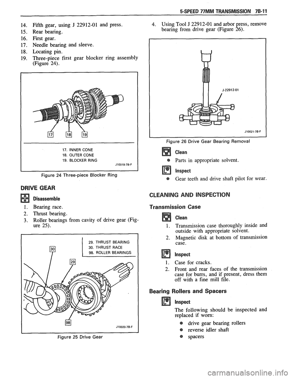
19. Three-piece first gear blocker ring assembly
(Figure
24).
17, INNER CONE
18. OUTER CONE
19. BLOCKER RING J10019-78-F
Figure 24 Three-piece Blocker Ring
DRIVE GEAR
Disassemble
1. Bearing race.
2. Thrust bearing.
3. Roller bearings from cavity of drive gear (Fig-
ure
25).
29. THRUST BEARING
30. THRUST RACE
98. ROLLER BEARINGS
J10020-78-F
4. Using Tool J 229 12-01 and arbor press, remove
bearing from drive gear (Figure
26).
-
Figure 26 Drive Gear Bearing Removal
Clean
@ Parts in appropriate solvent.
Gear teeth and drive shaft pilot for wear.
GLEANING AND INSPECnION
Transmission Case
Clean
1. Transmission case thoroughly inside and
outside with appropriate solvent.
2. Magnetic disk at bottom of transmission
case.
1. Case for cracks.
2. Front and rear faces of the transmission
case for burrs, and if present, dress them
off with a fine mill file.
Bearing Rollers and Spacers
The following should be inspected and
replaced if worn:
@ dkve gear bearing rollers
@ reverse idler shaft
@ spacers Figure 25 Drive Gear
Page 1149 of 1825
Gears .
t, Drive gear bearing rollers for chips,
cracks, or excessive wear and replace if
necessary.
@ Clutch sleeves to insure that they slide
freely on their hubs.
Front and Rear Bearings
Clean
t, Front and rear bearings thoroughly with
appropriate solvent.
1. Blow out bearings with compressed air.
NOTICE: Do not allow the bearings to spin.
Turn them slowly by hana. Spinning bearings
may damage the race and rollers.
2. Lubricate bearings with transmission lubricant.
@ Bearings for roughness by slowly turning
race by hand.
Synchronizer Blocking Rings
Firsthecond and thirdlfourth blocker rings are
lined with friction material and cannot be checked
visually for wear. Replacement is necessary when gap
between blocker teeth and adjacent clutch teeth is sig-
nificantly less than specified. Fifth gear blocker ring
is brass and can be checked visually for wear or
damage.
ThirdIFouHh Blocker Rings
Assemble
1. Third gear blocker ring to third gear with twist-
ing motion to fully seat.
2. Fourth gear blocker ring to main drive gear with
twisting motion to fully seat.
Measure
Gap between vertical faces of blocker teeth and
clutch teeth. Nominal gap is
.035 -.059 inches
(.88 - 1.5mm) for new blocker rings (Figure
30).
FirsvSecond Blocker Rings
Assemble
1. Three-piece first gear blocker ring assembly
with twisting motion to fully seat. 2.
Three-piece first gear
blocker ring assembly,
with needle bearing and bearing sleeve, to first
gear.
3. Three-piece second gear blocker ring assembly with twisting motion to fully seat.
4. Three-piece second gear blocker ring assembly,
with thrust washer, to second gear.
Measure
Gap between vertical faces of blocker teeth and
clutch teeth. Nominal gap is ,032
-.056 inches
(.81 -1.4mm) for new blocker ring assemblies
(Figure 30).
Synchronizer Keys and Springs
Figures 27,28,29
NOTICE: The synchronizer hubs and sliding
sleeves are a selected assembly and should be
kept together as originally assembled, but the
keys and springs may be replaced if worn or
broken.
Remove or Disconnect
1. If
relation of hub and sleeve are not already
marked, mark for assembly purposes.
2.
Push the sliding sleeve from the hub, the keys
will fall free and the springs may be easily
removed.
Install or Connect
1. Place a blocker ring on side of the hub and
sleeve and install keys and retain with a spring.
2. Place blocker ring on opposite side of hub and
sleeve and install remaining spring.
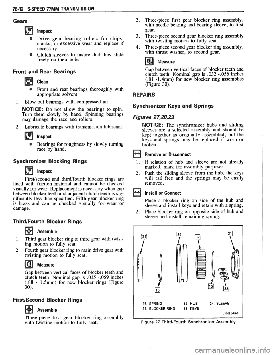
15. SPRING 32. HUB 34. SLEEVE
31. BLOCKER RING 33. KEYS
J 10022-78-F
Figure 27 Third-Fourth Synchronizer Assembly
Page 1150 of 1825
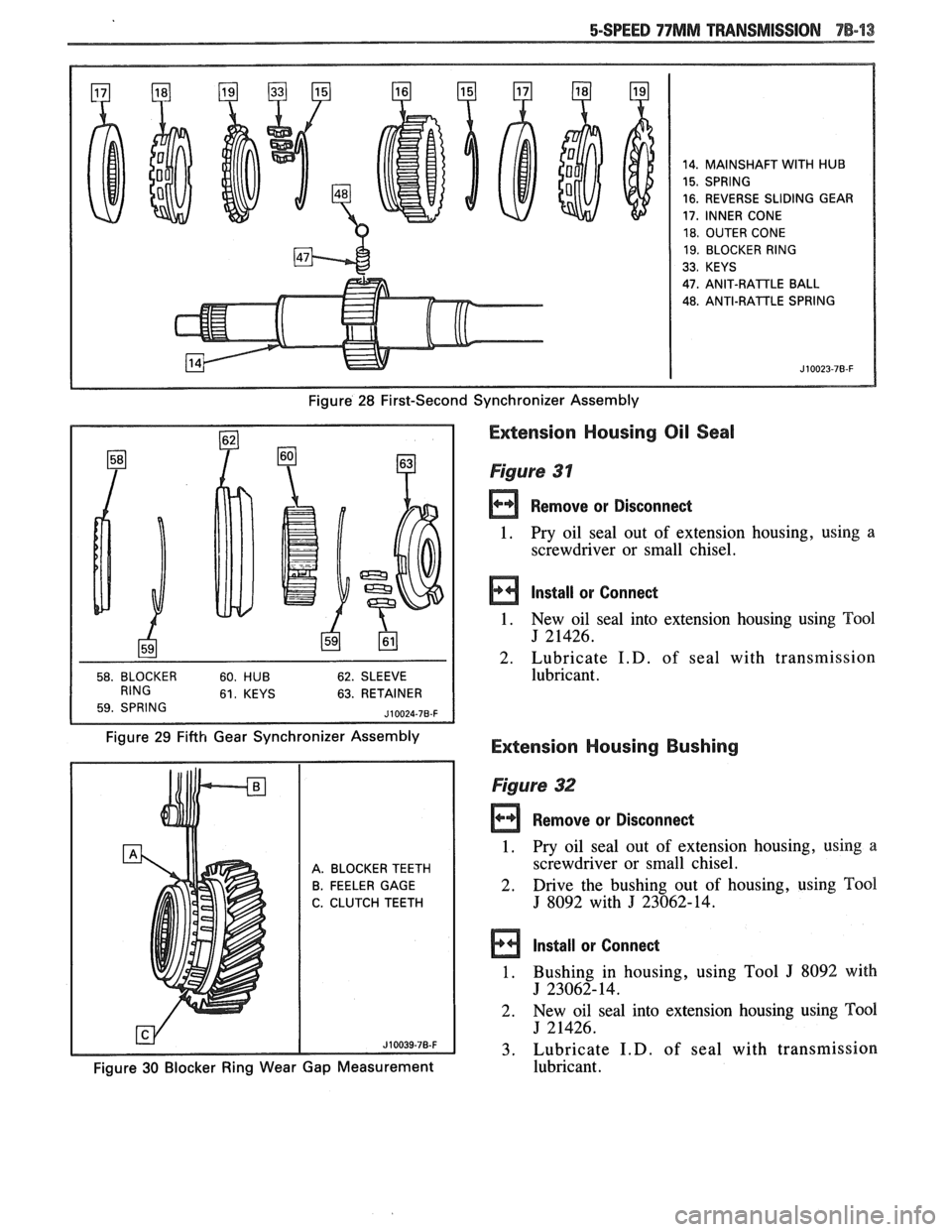
14. MAINSHAFT WITH HUB
15. SPRING
16. REVERSE SLIDING GEAR
17, INNER CONE
18. OUTER CONE
19. BLOCKER RING
33. KEYS
47.
ANIT-RAlTLE BALL
48. ANTI-RATTLE SPRING
Figure 28 First-Second Synchronizer Assembly
63. RETAINER
Figure 29 Fifth Gear Synchronizer Assembly
Extension Housing Oil Seal
Figure 31
Remove or Disconnect
1. Pry oil seal
out of extension housing, using a
screwdriver or small chisel.
Install or Connect
1. New oil seal into extension housing using Tool
J 21426.
2. Lubricate
I.D. of seal with transmission
lubricant.
Extension Housing Bushing
A. BLOCKER TEETH
B. FEELER GAGE
C. CLUTCH TEETH
Figure 32
rn Remove or Disconned
1. Pry oil seal out of extension housing, using a
screwdriver or small chisel.
2. Drive the bushing
out of housing, using Tool
J 8092 with J 23062-14.
Install or Connect
1. Bushing in housing, using Tool J 8092 with
J 23062-14.
2. New
oil seal into extension housing using
Tm1
J 21426.
3. Lubricate
I.D. of seal with transmission
Figure 30 Blocker Ring Wear Gap Measurement lubricant.
Page 1151 of 1825
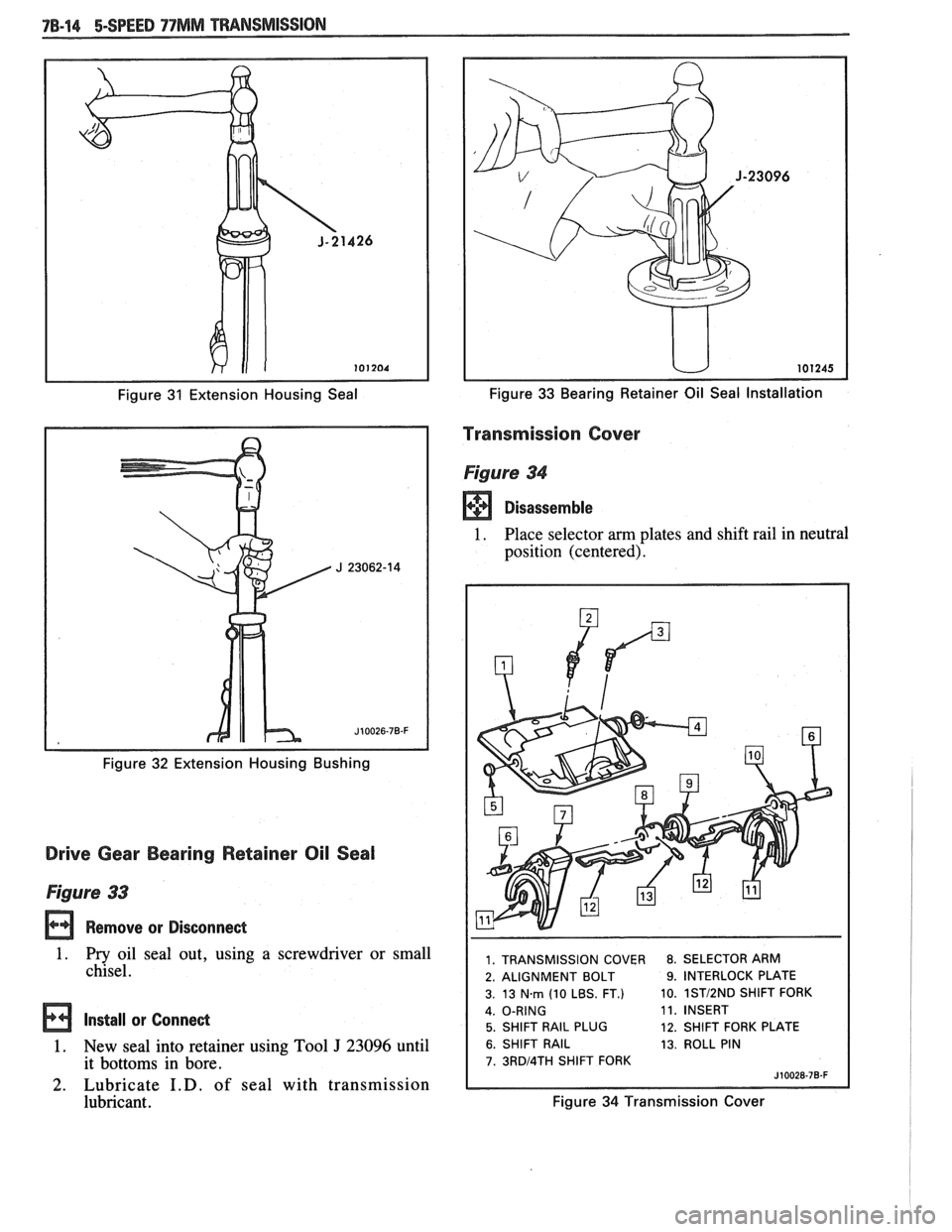
Figure 31 Extension Housing Seal
Figure
32 Extension Housing Bushing
Drive Gear Bearing Retainer Oil Seal
Figure 33
Remove or Disconnect
1. Pry oil seal out, using a screwdriver or small
chisel.
Install or Connect
1. New seal into retainer using Tool J 23096 until
it bottoms in bore.
2. Lubricate I.D. of seal with transmission
lubricant.
Figure 33 Bearing Retainer Oil Seal Installation
Transmission Cover
Figure 34
Disassemble
1. Place selector am plates and shift rail in neutral
position (centered).
1. TRANSMISSION COVER 8. SELECTOR ARM
2. ALIGNMENT BOLT
9. INTERLOCK PLATE
3. 13
Nm (10 LBS. FT.) 10. 1STI2ND SHlFT
FORK
11. INSERT
5. SHIFT RAIL PLUG 12. SHIFT FORK PLATE
6. SHIFT RAIL 13. ROLL PIN
7. 3RDl4TH SHlFT FORK
Figure 34 Transmission Cover