1988 PONTIAC FIERO transmission
[x] Cancel search: transmissionPage 1640 of 1825
WINDSHIELD WIPER SYSTEMS - F CARLINE 8E -13
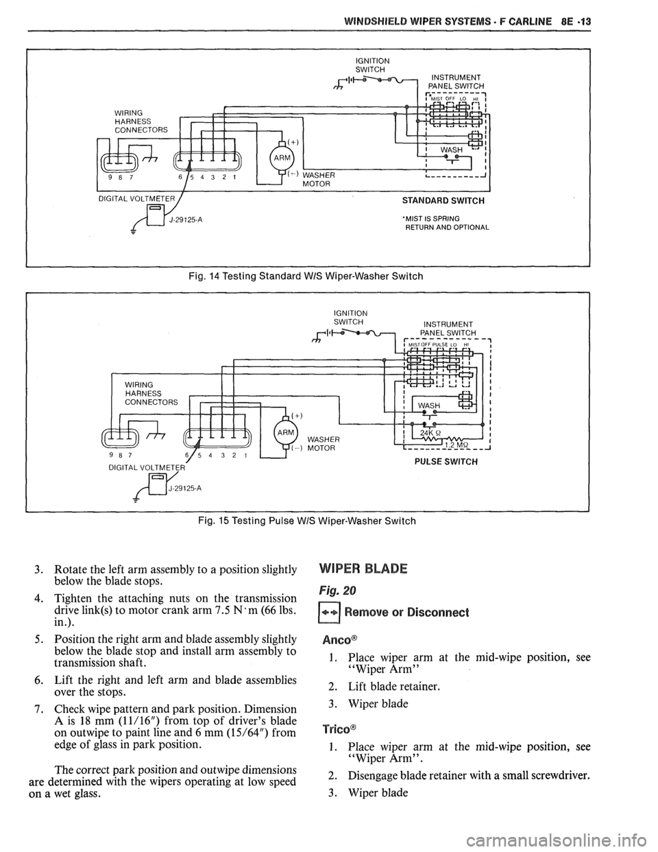
'MIST IS SPRING
RETURN AND OPTIONAL
Fig. 14 Testing Standard WIS Wiper-Washer Switch
Fig.
15 Testing Pulse WIS Wiper-Washer Switch
3. Rotate the left arm assembly to a position slightly
below the blade stops.
4. Tighten the attaching nuts on the transmission
drive
link(s) to motor crank arm 7.5 N'm (66 lbs.
in.).
5. Position the right arm and blade assembly slightly
below the blade stop and install arm assembly to
transmission shaft.
6. Lift the right and left arm and blade assemblies
over the stops.
7. Check wipe pattern and park position. Dimension
A is 18 mm (1 1/16") from top of driver's blade
on
outwipe to paint line and 6 mm (15/64") from
edge of glass in park position.
The correct park position and
outwipe dimensions
are determined with the wipers operating at low speed
on a wet glass.
WIPER BLADE
Fig. 20
Remove or Disconnect
Anso@
1. Place wiper arm at the mid-wipe position, see
"Wiper Arm"
2. Lift blade retainer.
3. Wiper blade
TY~GO@
1. Place wiper arm at the mid-wipe position, see
"Wiper Arm".
2. Disengage blade retainer with a small screwdriver.
3. Wiper blade
Page 1643 of 1825
8E -16 WINDSHIELD WIPER SYSTEMS - F CARLINE
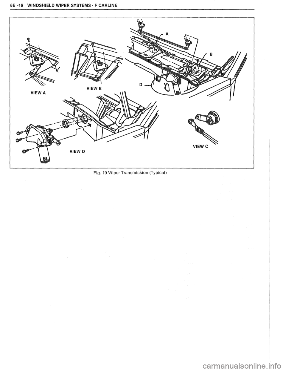
Fig. 19 Wiper Transmission (Typical)
Page 1644 of 1825
WiNDSWlEbB WIPER SYSTEMS - F CARLINE 8E -47
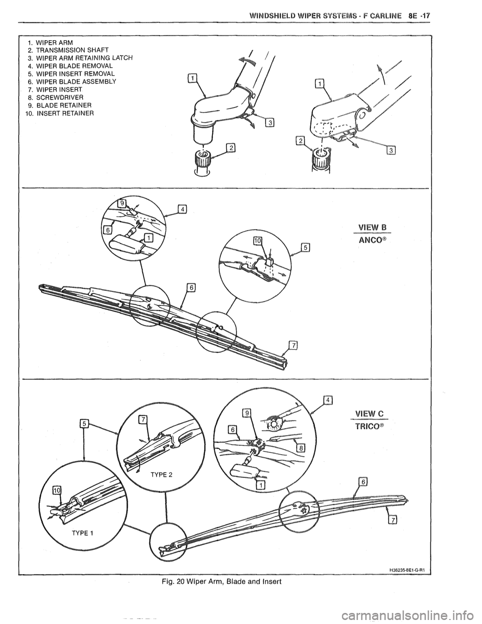
1. WlPER ARM
2. TRANSMISSION SHAFT
3. WIPER ARM RETAINING LATCH 4. WlPER BLADE REMOVAL
5. WlPER INSERT REMOVAL
6. WlPER BLADE ASSEMBLY 7. WlPER INSERT
8. SCREWDRIVER
9. BLADE RETAINER
10. INSERT RETAINER
Fig. 20 Wiper Arm, Blade and Insert
Page 1664 of 1825
CRUISE CONTROL 9B-1
SECTION 9B
SE CONTROL
CONTENTS
General Description ................................... 9B-1
Off/On/Resume/Accel Switch
Operation
................................................ 9B- 1
Set/Coast Button Switch .............................. 9B- 1
Electronic Controller (Module) .................... 9B-2
Servo Unit ..................................................... 9B-2
Speed Sensors ............................................. 9B-3
VSS Buffer Amplifier ................................ 9B-3
PM Generator Speed Signal ..................... 9B-3
Vacuum Supply ............................................. 9B -4
Electrical and Vacuum Release
Switches
..................................................... 9B-4
Electrical Harness ...................................... 9B-4
Diagnosis .................................................. 9B-4
Cruise System Surges .................................... 9B-4
Cruise Set Speed High or Low ..................... 9B-4
Excessive Cruise Speed Loss on Hills .......... 9B-4
Cruise Tap-Up and Tap-Down .................... 9B-4
On-Gar Service (Illustrated) ..................... 9B-6
Cruise Release Switches ............................... 9B-6
............................. Cruise Processor Module 9B-6
Vacuum Harness and Cable Routing -
VIN E ..................................................... 9B-7
Vacuum Harness and Cable Routing -
VIN S ......................................................... 9B-8
Vacuum Harness and Cable Routing -
VIN F,8 ..................................................... 9B-9
Servo Mounting - VIN S,F .......................... 9B-10
....................... Servo and Bracket - VIN E 9B-10
Vacuum Tank - VIN S,F,E ....................... 9B-10
GENERAL DESCRIPTION
Cruise control is a speed control system which
maintains a desired car speed under normal driving
conditions. However, steep grades up or down may
cause variations in the selected speeds. The electronic
cruise control system has the capability to cruise, coast,
resume speed, accelerate, and "tap-up" and
" tap-down" .
The main parts of the cruise control system are
the mode control switches, controller (module), servo
unit, speed sensor, vacuum supply, electrical and
vacuum release switches, and electrical harness.
The cruise control system uses vacuum to operate
a throttle servo unit. The servo unit maintains a desired
car speed by trapping vacuum in the servo unit at the
proper servo position. The controller monitors vehicle
speed and servo position and operates the vacuum and
vent valves in the servo to maintain desired speed. The
controller contains a low speed limit which will prevent
system engagement below a minimum speed of about
25 mph. The operation of the controller is controlled
by mode control switches located in the end of the
directional signal lever. To disengage the system, two
release switches are provided. An electrical release
switch mounted on the brake pedal bracket (brake and
clutch pedal bracket on cars equipped with manual
transmission) disengages the system electrically when
the brake pedal (or clutch pedal) is depressed. A
vacuum release valve, mounted on the brake pedal
bracket, vents the trapped vacuum in the servo to
atmosphere when the brake pedal is depressed,
allowing the servo unit to quickly return the throttle
to idle position.
.
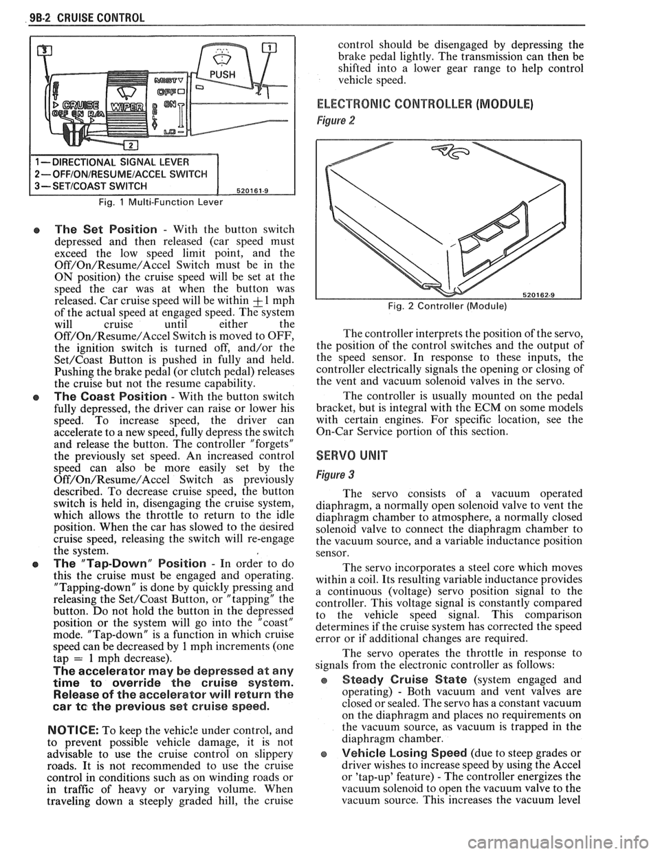
OFF/ON/RESUME/ACCEL SWITCH
(OPERATION)
Figure 1
The Off/On/Resume/Accel Switch has three
positions. This switch turns the cruise control system
ON and OFF and also returns cruise control operation
to the last speed setting when MOMENTARILY
moved towards the R/A position after braking. (Do
not hold the slider in the R/A position
... release it
immediately.) If the slider is held in the R/A position
for more than one second, the system goes into the
Accel mode. To accelerate the car, move the slider
switch to the R/A position and hold it there until the
car reaches the desired speed. When the slider switch
is released, the system will maintain the new cruise
speed. In order to use the Accel mode, the cruise
OFF/ON/Resume/Accel switch must be in the "ON"
position and the car must be above the low speed limit
of
25 mph.
The slide switch can also be used to "tap-up" car
speed. In order to do this the cruise must be engaged
and operating. "Tapping-up" is done by quickly
pressing the slide switch toward the R/A position and
quickly releasing it, or "tapping" the lever. Do not hold
the lever in the R/A position or the system will go into
the Accel mode. "Tap-up" is a function in which cruise
speed can be increased by
1 mph increments (one tap
= 1 mph increase).
SET/COAST BUTTON SWITCH
Figure 1
The cruise control Set/Coast Switch (located in
the end of the turn signal lever) has two positions
-
"Normal" and "Depressed".
Page 1665 of 1825
98-2 CRUISE CONTROL
Fig. 1 Multi-Function Lever
e The Set Position - With the button switch
depressed and then released (car speed must
exceed the low speed limit point, and the
Off/On/Resume/Accel Switch must be in the
ON position) the cruise speed will be set at the
speed the car was at when the button was
released. Car cruise speed will be within
& 1 mph
of the actual speed at engaged speed. The system
will cruise until either the
Off/On/Resume/Accel Switch is moved to OFF,
the ignition switch is turned off, and/or the
Set/Coast Button is pushed in fully and held.
Pushing the brake pedal (or clutch pedal) releases
the cruise but not the resume capability.
The Coast Position - With the button switch
fully depressed, the driver can raise or lower his
speed. To increase speed, the driver can
accelerate to a new speed, fully depress the switch
and release the button. The controller "forgets"
the previously set speed. An increased control
speed can also be more easily set by the
Off/On/Resume/Accel Switch as previously
described. To decrease cruise speed, the button
switch is held in, disengaging the cruise system,
which allows the throttle to return to the idle
position. When the car has slowed to the aesired
cruise speed, releasing the switch will re-engage
the system.
e The "Tap-Down" Position - In order to do
this the cruise must be engaged and operating.
"Tapping-down" is done by quickly pressing and
releasing the
Set/Coast Button, or "tapping" the
button. Do not hold the button in the depressed
position or the system will go into the "coast"
mode. "Tap-down" is a function in which cruise
speed can be decreased by
1 mph increments (one
tap = 1 mph decrease).
The accelerator may be depressed at any
time
to override the cruise system.
Release of the accelerator will return the
car
te the previous set cruise speed.
NOTICE:
To keep the vehic:e under control, and
to prevent possible vehicle damage, it is not
advisable to use the cruise control on slippery
roads. It is not recommended to use the cruise
control in conditions such as on winding roads or
in traffic of heavy or varying volume. When
traveling down
a steeply graded hill, the cruise control
should be disengaged by depressing the
bralte pedal lightly. The transmission can then be
shifted into a lower gear range to help control
vehicle speed.
ELECTRONIC CONTROLLER (MODULE)
Figure 2
Fig. 2 Controller (Module)
The controller interprets the position of the servo,
the position of the control switches and the output of
the speed sensor. In response to these inputs, the
controller electrically signals the opening or closing of
the vent and vacuum solenoid valves in the servo.
The controller is usually mounted on the pedal
bracket, but is integral with the ECM on some models
with certain engines. For specific location, see the
On-Car Service portion of this section.
SERVO UNIT
Figure 3
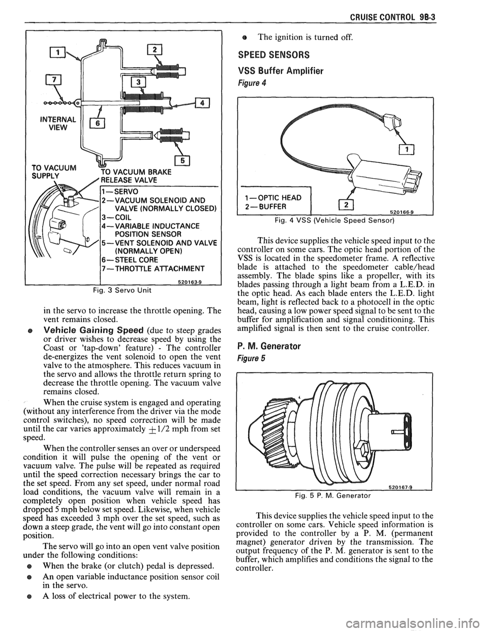
The servo consists of a vacuum operated
diaphragm, a normally open solenoid valve to vent the
diaphragm chamber to atmosphere, a normally closed
solenoid valve to connect the diaphragm chamber to
the vacuum source, and a variable inductance position
sensor.
The servo incorporates a steel core which moves
within a coil. Its resulting variable inductance provides
a continuous (voltage) servo position signal to the
controller. This voltage signal is constantly compared
to the vehicle speed signal. This comparison
determines if the cruise system has corrected the speed
error or if additional changes are required.
The servo operates the throttle in response to
signals from the electronic controller as follows:
Steady Cruise State (system engaged and
operating)
- Both vacuum and vent valves are
closed or sealed. The servo has a constant vacuum
on the diaphragm and places no requirements on
the vacuum source, as vacuum is trapped in the
diaphragm chamber.
e Vehicle Losing Speed (due to steep grades or
driver wishes to increase speed by using the Accel
or 'tap-up' feature)
- The controller energizes the
vacuum solenoid to open the vacuum valve to the
vacuum source. This increases the vacuum level
Page 1666 of 1825
CRUISE CONTROL 98-3
CUUM BRAKE
-VARIABLE INDUCTANCE
POSITION SENSOR
-VENT SOLENOID AND VALVE
(NORMALLY OPEN)
6-- STEEL CORE
Fig. 3 Servo Unit
in the servo to increase the throttle opening. The
vent remains closed.
e Vehicle Gaining Speed (due to steep grades
or driver wishes to decrease speed by using the
Coast or 'tap-down' feature)
- The controller
de-energizes the vent solenoid to open the vent
valve to the atmosphere. This reduces vacuum in
the servo and allows the throttle return spring to
decrease the throttle opening. The vacuum valve
remains closed.
When the cruise system is engaged and operating
(without any interference from the driver via the mode
control switches), no speed correction will be made
until the car varies approximately
+ - 1/2 mph from set
speed.
When the controller senses an over or underspeed
condition it will pulse the opening of the vent or
vacuum valve. The pulse will be repeated as required
until the speed correction necessary brings the car to
the set speed. From any set speed, under normal road
load conditions, the vacuum valve will remain in a
completely open position when vehicle speed has The
ignition is turned off.
SPEED SENSORS
VSS
Buffer Amplifier
Figure 4
Fig. 4 VSS (Vehicle Speed Sensor)
This device supplies the vehicle speed input to the
controller on some cars. The optic head portion of the
VSS is located in the speedometer frame. A reflective
blade is attached to the speedometer
cable/head
assembly. The blade spins like a propeller, with its
blades passing through a light beam from a
L.E.D. in
the optic head. As each blade enters the
L.E.D. light
beam, light is reflected back to a photocell in the optic
head, causing a low power speed signal to be sent to the
buffer for amplification and signal conditioning. This
amplified signal is then sent to the cruise controller.
P. M. Generator
Figure 5
dropped 5mph below set speed. Likewise, when vehicle
speed has exceeded
3 mph over the set speed, such as This
device supplies the vehicle speed input to the
down a steep grade, the vent will go into ,-onstant open ~0ntI-011er on some cars. Vehicle speed information is
position. provided
to the controller by a P. M. (permanent
magnet) generator driven by the transmission. The
The servo go into an 'Pen vent position output frequency of the P. M, generator is sent to the under the following conditions:
buffer, which amplifies and conditions the signal to the
@ When the brake (or clutch) pedal is depressed. controller.
a An open variable inductance position sensor coil
in the servo.
a A loss of electrical power to the system.
Page 1682 of 1825
GENERAL INFORMATION - F STYLE 1 H-1
SECTION IH
GENERAL NFORMAT
NOTICE: The anti-theft label found on some major sheet metal, engines, and transmissions must be masked
prior to painting, rustproofing, undercoating, etc. The mask
must be removed following the above operations.
Failure to keep the label clean and readable may result in liability for violation of Federal Vehicle Theft Prevention
Standard, and subject the vehicle owner to possible suspicion that the part was stolen.
Lock Cylinder Coding
..................................... I H-1 Chip Resistant Plastisol Material .................... 1 H-8
...................................................... Lubrication 1 H-2 Flexible Exterior Plastic Parts ......................... 1H-9
Adhesive Body Side Moldings ......................... 1H-3 Metal Replacement Parts Finishing ................ lH-13
Waterleak Diagnosis and Repair ..................... 1H-3 Interior Plastic Trim Parts Finishing .............. 1H-13
.................................................... Anticorrosion Treatment ................................ IH-4 Special Tools I H- 14
LOCK CYL!NDER CODING o Check key operation in the lock cylinder.
KEY IDENTIFICATION AND USAGE
REPLACEMENT LOCK CYLINDERS
The lock cylinder keyway is designed so that
other model keys will not enter a current model lock
cylinder. Two noninterchangeable keys are used.
CB Square headed key is used in the ignition lock
cylinder.
o Oval headed key is used in all other lock
cylinders.
Key identification is obtained from the four
character key code stamped on the knockout portion
of the key head and an identification letter stamped on
the key shank. After the code number has been
recorded by the owner, the plugs should be knocked
out of the key head. From these numbers, the lock
combination can be determined by use of a code list
(available to owners of key cutting equipment from
equipment suppliers). If key code numbers are not
available from records or from the knockout plug, the
lock combination (tumbler numbers and position) can
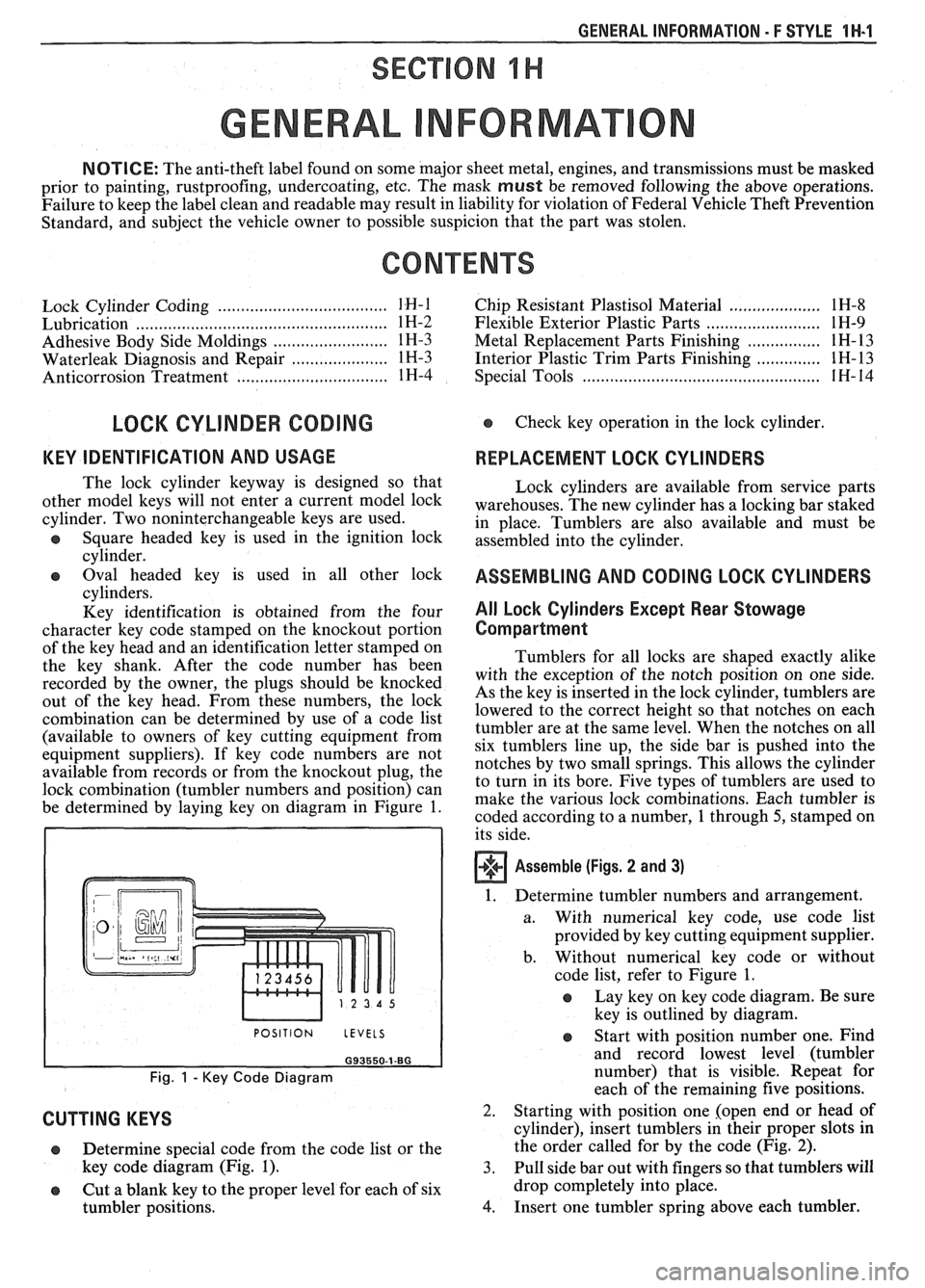
be determined by laying key on diagram in Figure
1.
I POSITION LEVELS I
Fig. 1 - Key Code Diagram
CUTTING KEYS
Lock cylinders are available from service parts
warehouses. The new cylinder has a locking bar staked
in place. Tumblers are also available and must be
assembled into the cylinder.
ASSEMBLING AND CODING LOCK CYLINDERS
All Lock Cylinders Except Rear Stowage
Compartment
Tumblers for all locks are shaped exactly alike
with the exception of the notch position on one side.
As the key is inserted in the lock cylinder, tumblers are
lowered to the correct height so that notches on each
tumbler are at the same level. When the notches on all
six tumblers line up, the side bar is pushed into the
notches by two small springs. This allows the cylinder
to turn in its bore. Five types of tumblers are used to
make the various lock combinations. Each tumbler is
coded according to a number,
1 through 5, stamped on
its side.
Assemble (Figs. 2 and 3)
1. Determine tumbler numbers and arrangement.
a. With numerical
key code, use code list
provided by key cutting equipment supplier.
b. Without numerical
key code or without
code list, refer to Figure
1.
o Lay key on key code diagram. Be sure
key is outlined by diagram.
Determine special code from the code list or the
key code diagram (Fig.
1). 3.
o Cut a blank key to the proper level for each of six
tumbler positions.
4.
Start with position number one. Find
and record lowest level (tumbler
number) that is visible. Repeat for
each of the remaining five positions.
Starting with position one [open end or head of
cylinder), insert tumblers in their proper slots in
the order called for by the code (Fig.
2).
Pull side bar out with fingers so that tumblers will
drop completely into place.
Insert one tumbler spring above each tumbler.
Page 1710 of 1825
FRONT END - F STYLE 41-1-1
SECTION 4H
FRONT END
NOTICE: The anti-theft label found on some major sheet metal, engines, and transmissions must be masked
prior to painting, rustproofing, undercoating, etc. The
mask must be removed following the above operations.
Failure to keep the label clean and readable may result in liability for violation of Federal Vehicle Theft Prevention
Standard, and subject the vehicle owner to possible suspicion that the part was stolen.
CONTENTS
.............................................................................................................. Body Ventilation 4H- 1
Shroud Side Trim Finishing Panel ................................................................................ 4H- 1
Pressure Relief Valve .................................................................................................. 4H- 1
Hood Latch Release Cable ............................................................................................ 4H- 1
The body ventilation system on styles without air
conditioning consists of a fresh air intake located at the
front plenum chamber. Air enters the front plenum
chamber through an air intake grille screen (Fig.
1).
Air passes through the plenum chamber to air outlet
doors. When ventilation controls are operated, air
enters past the doors and into the body from outlets in
the dash panel. The air then passes through the body,
around the rear seat, into the rear compartment to the
rear quarters and leaves the body passing through the
pressure relief valves on the rear body lock pillars (Fig.
4). For complete instructions on operation of the body
ventilation system, refer to the owner's manual.
Water entering the plenum chamber is drained
through openings provided for that purpose.
FRONT END SEALING
All potential waterleak locations are sealed in
production with high quality durable sealers. Should it
be necessary to reseal specific areas, a high quality
medium-bodied sealer which will remain flexible after
curing and can be painted should be used.
SHROUD SIDE TRIM FINISHING PANEL
Removal and Installation
1. Remove shroud side trim finishing panel screws
(Fig. 2).
2. Pull down and rearward on trim finishing panel
to release hood cable handle from slot on left side.
On right side, pull rearward to remove panel from
windshield lower side garnish (Figs.
2 and 3).
3. To install, reverse removal procedures.
PRESSURE RELIEF VALVE
The pressure relief valves are attached to rear
lock pillars (in door opening below belt) with screws.
Figure
4 shows pressure relief valve installations.
Removal and Installation
1. Remove louver-to-lock pillar screw located in the
door opening (Fig.
4).
2. Slide louver up to disengage hook-type attaching
clip to complete removal.
3. To install, reverse removal procedure.
HOOD LATCH RELEASE CABLE
The one-piece hood latch release cable includes
pull handle, control cable and housing. The control
cable is installed through the left shroud side trim
panel. A sealing grommet attached to the dash panel
completes the assembly (Figs. 2 and
5).
Removal and Installation
The shroud side finishing panels are designed
with an integral hinge pillar pinchweld finishing lace.
The left side has a cutout slot for the hood release cable
handle. There is no need to remove the cable assembly
2.
when removing the trim finishing panel. The trim 3.
finishing panel is secured to the side shroud with
self-tapping attaching screws.
4.
Raise hood and disengage cable from hood latch
assembly. Block latch to prevent hood locking
until cable has been reinstalled.
Remove left shroud side trim panel.
Disengage control assembly housing from cutout
of trim panel and remove
cable assembly from
panel.
To install, reverse the removal procedure.